HP NetServer LH 3r, LH 4r, LH 3000r, and LH 6000r Installation Guide for Compaq® 4000/7000 Racks HP Part Number 5969-5924 Printed in November 1999
Notice The information contained in this document is subject to change without notice. Hewlett-Packard makes no warranty of any kind with regard to this material, including, but not limited to, the implied warranties of merchantability and fitness for a particular purpose. Hewlett-Packard shall not be liable for errors contained herein or for incidental or consequential damages in connection with the furnishing, performance, or use of this material.
Contents 1 Introduction ................................................................................................. 1 HP NetServer – Compaq Rack Precautions ................................................... 4 2 Overview ...................................................................................................... 5 3 Installation ................................................................................................... 7 Preparation...................................................
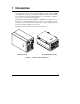
1 Introduction This document describes how to mount an HP NetServer LH 3r, LH 4r, LH3000r, or LH 6000r into a Compaq® model 4000- or 7000-series rack enclosure. Refer to the documentation that came with the HP NetServer for instructions on adding accessories to, and configuring the NetServer. The HP NetServer LH 3r, LH 4r, LH3000r, or LH 6000r (the pedestal versions of this NetServer) cannot be installed in a rack enclosure.
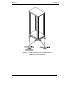
Chapter 1 Introduction WARNING To prevent the rack from tipping over and causing equipment damage or bodily injury, be sure that the stabilizing, anti-tip feature is installed on this rack enclosure see Figure 1-2. WARNING To prevent the rack from tipping over and causing equipment damage or bodily injury, do not extend more than one piece of equipment at a time out of the front of the rack enclosure.
Chapter 1 Introduction Figure 1-2.
Chapter 1 Introduction HP NetServer – Compaq Rack Precautions CAUTION If this NetServer is not installed according to these instructions, damage to the NetServer or accessories may result. Damage due to improper installation is not covered by the HP Warranty. Observe the precautions listed in this section to maintain the NetServer’s reliability. When installing this HP NetServer in a Compaq rack enclosure, certain requirements must be addressed to assure that the needs of the NetServer are met.
2 Overview The steps required to install the NetServer in the rack are summarized below: NOTE This is only a summary; detailed instructions are provided on the following pages. • Measure and mark the appropriate holes on all four rack columns. • Install one bar nut on each of the four rack columns. • Insert two cage nuts on each of the two front columns only. • Attach the slides to the columns. • Extend the slides. • Remove power supply modules and hot-swap drives from the NetServer.
Chapter 2 Overview Terms used in this document are defined in the table below. Term 6 Definition Bar nut Short, threaded bar used behind slide mounting flanges. Used in place of individual nuts to mate with slide mounting screws. Bezel Removable plastic fascia panel that covers entire front of the NetServer. This NetServer includes two bezels: one for installation in HP rack enclosures, and one for installation in Compaq 4000/7000 series rack enclosures.
3 Installation This section contains detailed instructions for installing an HP NetServer NetServer LH 3r, LH 4r, LH 3000r, or LH 6000r in the model 4000/7000 series of Compaq rack enclosures. Preparation Before beginning the installation of the NetServer into the rack, you must prepare the rack and the NetServer. Determine the location at which the NetServer is to be installed in the rack enclosure. Mark the bottom and top of this location on the rack columns. The HP NetServer measures 8 EIA units tall.
Chapter 3 Installation 22nd 20th 22nd 20th (At Rear Of Column) 22nd 20th 19th 22nd 20th 15th 11th 14th Figure 3-1. Marking Holes for Installation Mark two holes on each of the front columns to use for rack nuts where the two recessed mounting brackets attach to the columns. When the installation is complete, these brackets secure the NetServer in the rack enclosure. To mark the bracket mounting holes refer to Figure 3-1: 1.
Chapter 3 Installation Installing the Bar Nuts, Screws, and Cage Nuts Once you have marked the appropriate holes, install the bar nuts and screws on the columns: 1. Position one bar nut behind holes 20 and 22 (previously marked). 2. Insert the two screws, with flat washers, through the two holes and start them into the bar nut see Figure 3-2. Do not tighten these screws, yet. 3. Repeat for all columns. Rack Column Bar Nut Washers Screws Figure 3-2.
Chapter 3 Installation Mounting the Slides 1. Orient each slide so that the front of the slide attaches to the front column and the rear attaches to the rear column. This ensures that once installed, the slides will extend correctly, toward the front of the rack see Figure 3-3. NOTE The slides do not come apart; they are one piece. Rear Flange Front Flange Dimple Extendible Members Figure 3-3.
Chapter 3 2. Installation Place the mounting flange of the slide between the inside of the column and the bar nut. See Figure 3-4. Do this at the front and rear of the slide. Push In and Up Figure 3-4. Mounting a Slide to a Column 3. If your slide has the dimple shown in Figure 3-3, center the dimple in the square hole on the rack column. 4. Press the slide firmly against the screws. Lift up against the screws. 5. While lifting the slide, tighten all four screws to secure the slide.
Chapter 3 Installation Installing the NetServer The NetServer now must be mounted to the slides, the cable management arm can be installed, the recessed mounting brackets must be installed, the control panel must be relocated, and the Compaq rack-compatible bezel must be installed. Mounting the NetServer to the Slides 1. Extend the slides until you hear a click, indicating they are fully extended in the locked-out position. Note that the slides do not come apart see Figure 3-3.
Chapter 3 Installation 3. Using two people, lift the NetServer using the handles on each side. Move the NetServer in between the extended slide members and position the it so that the handles are resting on the slide members see Figure 3-5 and Figure 3-6. Figure 3-5.
Chapter 3 Installation 4. Line up the mounting holes in the slide members with the holes in the NetServer chassis, insert three screws on each side, and tighten them see Figure 3-6. Figure 3-6.
Chapter 3 Installation 5. Remove two screws from each of the four handles and remove handles see Figure 3-7. Keep these handles and screws for later use, in case you need to remove the NetServer and ship it. Figure 3-7. Remove Mounting Handles 6. Reinstall power supply modules and hard disk modules removed earlier.
Chapter 3 Installation Optional for HP NetServer LH 3000r and LH 6000r, Install Cable Management Arm The HP NetServer Cable Management Arm supplied with the HP LH 3000r and LH 6000r allows the cables, including the power cord, to move in and out with the HP NetServer chassis on its slides without being accidentally disconnected. See Figure 3-8. Rear of NetServer Left Rear Rack Column Cable Management Arm Figure 3-8.
Chapter 3 Installation 3. Install the two 6-32 pin head Torx T-15 screws in the two threaded holes on the rear of the NetServer. 4. Orient the cable management arm as shown in Figure 3-8. 5. Install the flange over the 6-32 screws and tighten them. 6. Attach the other flange of the cable arm to the rear column of the rack with the two M-6 pan head Phillips screws, included with the arm.
Chapter 3 Installation Installing the Recessed Mounting Brackets The NetServer is held in the closed retracted position inside the rack enclosure by two recessed brackets. These are attached to the face of the NetServer chassis and the two front rack columns. To install these brackets: 1. On both slide members, simultaneously depress the lockout releases and push the NetServer completely into the rack enclosure see Figure 3-9. Lockout Release Figure 3-9.
Chapter 3 Installation 2. Install the four screws that hold the tall, left-hand bracket to the face of the NetServer chassis and to the rack column see Figure 3-10. 3. Install the four screws that hold the short, right-hand bracket to the face of the NetServer chassis and to the rack column see Figure 3-10. Recessed Brackets Figure 3-10.
Chapter 3 Installation CAUTION Take care to not damage the ribbon cable that connects the control panel to the NetServer. 5. Reinstall the control panel in the leftmost slots, and install and tighten the screws. To avoid damaging the ribbon cable, verify that the ribbon cable goes completely back inside the NetServer before mounting the control panel. NOTE There are two possible locations for the control panel. Only the leftmost position is correct for Compaq rack installations.
Chapter 3 Installation 6. Mount the control panel bezel over the control panel see Figure 3-12. Install the bezel tabs into the leftmost slots. Mounting Slots for Compaq racks (on left) Mounting Slots for HP rack (on right) Figure 3-12.
Chapter 3 Installation Installing the Bezel Align the locating tabs on the Compaq rack-compatible bezel with the holes in the NetServer front panel, and clip the bezel onto the front of the NetServer see Figure 3-13. Figure 3-13.
4 Warranty and Support The hardware warranty below applies to components purchased as accessories. If your component was factory installed as part of a HP NetServer model, refer to the HP NetServer Warranty and Service/Support Booklet for the warranty limitations, customer responsibilities, and other terms and conditions.
Chapter 4 Warranty and Support Third-Party Hardware Products HP does not warrant third-party hardware products. Third-party hardware products may be warranted in accordance with the third-party warranty statement accompanying the product. On-site visits caused by third-party hardware products—whether internal to the HP NetServer system processor unit (such as non-HP DIMMs) or external to the system processor unit (such as LAN cabling)—are subject to standard per-incident travel and labor charges.
Index B Bezel, control panel, 21 Bezel, NetServer, 22 C Cable management arm, 16 Compaq, 1 Control panel, 19 Control panel bezel, 21 F Fastening server to rack front, 18 Fastening server to slides, 14 H Handles, removing after mounting, 15 Hardware accessories limited warranty, 23 I Installing the NetServer, 12 Lockout releases, 18 M Mounting Brackets, 18 Mounting, NetServer, 12 N NetServer, installing, 12 R Recessed brackets, attaching, 19 S Slide location, 7 Support, 24 V Version of NetServer, 1 W Warnin