HP NetServer LXr Pro8 User Guide
Notice The information contained in this document is subject to change without notice. Hewlett-Packard makes no warranty of any kind with regard to this material, including, but not limited to, the implied warranties of merchantability and fitness for a particular purpose. Hewlett-Packard shall not be liable for errors contained herein or for incidental or consequential damages in connection with the furnishing, performance, or use of this material.
Contents 1 Setting Up the HP NetServer LXr Pro8........................................................1 Before You Set Up Your HP NetServer ..........................................................1 Setup Steps ...................................................................................................1 2 Controls, Indicators, and Ports ....................................................................5 Front Panel Controls ........................................................................
Removing a 128 MB SDRAM DIMM Module ................................................ 42 Installing the 4 GB Memory Board................................................................ 43 6 Installing Additional Boards....................................................................... 45 Introduction.................................................................................................. 45 Installing Accessory Boards .........................................................................
Setup Utility ................................................................................................. 75 Starting the Setup Utility .......................................................................... 75 Main Menu............................................................................................... 76 Using the Setup Screens.......................................................................... 76 Changing the Server Password ......................................................
Automated Fax ............................................................................................ 99 Telephone Support....................................................................................... 99 Obtaining HP Repair and Telephone Support............................................. 100 U.S. and Canada ................................................................................... 100 Europe.............................................................................................
Notice for Consumers in Australia .............................................................. 116 Notice For Consumers In New Zealand ...................................................... 116 Notice for Mexico: Hardware Warranty Statement...................................... 116 Póliza de Garantía ................................................................................. 117 Condiciones ........................................................................................... 117 Notas ........
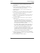
1 Setting Up the HP NetServer LXr Pro8 Before You Set Up Your HP NetServer Before you set up your HP NetServer: • Read the Rack Installation Road Map for this HP NetServer. The Road Map shows how to set up the entire rack system. It will alert you to issues you must consider before installing the HP NetServer itself. • Read this chapter. This chapter tells how to set up and configure the HP NetServer LXr Pro8. It tells you what to do, and in what order.
Chapter 1 Setting Up the HP NetServer LXr Pro8 3. Store the empty boxes and packing material in a safe place. This is especially important if you plan to ship the HP NetServer elsewhere for final installation. 4. If you have options to add to the HP NetServer’s satellite chassis (memory, accessory boards, processor boards), remove the appropriate access panels from the satellite. (Refer to Chapter 3.) 5. Install additional memory or memory boards in the satellite chassis. (Refer to Chapter 5.) 6.
Chapter 1 Setting Up the HP NetServer LXr Pro8 13. Insert the Navigator CD-ROM, reboot, and check the Navigator README file for important installation information. (Refer to Chapter 9.) 14. Configure the HP NetServer with Configuration Assistant from the Navigator CD-ROM. Choose the Express Configuration option. (Refer to Chapter 9.) NOTE To fully configure the HP NetServer, all the rack components should be cabled and online (though not necessarily installed in the rack.) 15.
2 Controls, Indicators, and Ports Front Panel Controls Run Indicator DC Output Indicator AC Input Indicator Attention Indicator DC Power Switch Message Display Reset Switch Figure 2-1.
Chapter 2 Controls, Indicators, and Ports Table 2-1. Control Panel Switch and Indicator Definitions Control Description DC Power Switch Turns the system on, or returns it to standby. Reset Switch Press to perform a warm boot of the system. Run Indicator During system startup: lights green to indicated that the system passed the Power On Self Test and is starting to boot. During normal operation: should stay green continuously during normal operation to indicate that the BIOS is running.
Chapter 2 Controls, Indicators, and Ports Power Supply Indicators Each of the HP NetServer LXr Pro8's power supplies has these indicators: DC Output AC Input Indicator Indicator Attention Indicator Figure 2-2. Power Supply LEDs Table 2-2. Power Supply LEDs Control Description DC Output Indicator Green indicates that DC power is online. During normal operation, this LED should always be green. AC Input Indicator Green indicates that the power supply is receiving AC power.
Chapter 2 Controls, Indicators, and Ports Rear Panel Controls, Ports, and Indicators Serial Port A Serial Port B Mouse Port Keyboard Port I2C Connector Fan Pack Temperature Indicator Power Interlock Switch Parallel Port Ejector Handle Ejector Handle Fan Pack Temperature Indicator AC Power Plug Figure 2-3.
Chapter 2 Controls, Indicators, and Ports Table 2-3. Rear Panel Control and Indicator Definitions Control Description Power Interlock Switch This switch is mounted on the base chassis. When you turn this switch clockwise, you disable DC power and release the satellite chassis. You can then pull out the satellite chassis and open the satellite's top cover. Satellite Ejector Handles These handles are mounted on the satellite chassis. Use them to pull the satellite out from the base chassis.
Chapter 2 Controls, Indicators, and Ports Power-Up and Power-Down Procedures Power-Up Procedure 1. Make sure that the power interlock switch at the rear of the HP NetServer is in the locked position, and that AC power is connected. When the switch is locked, the slot through the middle of the switch is vertical. See Figure 2-4. ◊ If the power interlock switch was unlocked, the system starts as soon as you relock the switch if AC power is connected. Skip ahead to step 3.
Chapter 2 Controls, Indicators, and Ports 2. Press the DC power button on the HP NetServer's control panel. The system now powers up. DC Power Figure 2-5. HP NetServer LXr Pro8 Control Panel 3. Turn on the monitor. Power Down Procedure 1. Log off all users. Shut down all networking software and applications. 2. Press the DC power switch on the HP NetServer's control panel (Figure 2-5). Normally, this is the complete procedure. 3.
Chapter 2 Controls, Indicators, and Ports If powering down the system for service, turn the power interlock switch to this position. Figure 2-6. Power Interlock Switch in Unlocked Position NOTE After you unlock the power interlock switch, DC power is turned off for all components within the satellite chassis except for five volts at the system control board, which is located on the SCSI extender tray in the bottom of the system's lower board cage.
Chapter 2 Controls, Indicators, and Ports When preparing your site for installation, allow for the additional inrush current. Since maximum inrush current for the HP NetServer LXr Pro8 is 80 amps for more than 10ms, the following circuit breaker recommendations need to be followed before installing the server in your environment: • In North American, a 20-amp-minimum circuit is to be used with one NEMA AB1 class 14B breaker for each 16-amp PDU.
3 Opening and Closing the HP NetServer Multiple Points of Access The HP NetServer LXr Pro8 is designed for easy access to all components. It features a satellite chassis which you can extend or detach from the main chassis for servicing. The satellite chassis contains the HP NetServer’s logic and memory boards. These boards are installed in two card cages, each with its own access route. The main chassis, or base chassis, holds the power supplies, control panel, and mass storage.
Chapter 3 Opening and Closing the HP NetServer Figure 3-1. Removing the HP NetServer’s Front Bezel To replace the front bezel: 1. Hold it up in front of the HP NetServer. Press the bezel’s bottom edge against the server. Make sure that the bottom of the bezel hooks under the two metal tabs mounted on the front of the server. 2. Firmly press the top of the bezel onto the front of the HP NetServer until you hear a click.
Chapter 3 Opening and Closing the HP NetServer NOTE If the HP NetServer is mounted in the rack at an awkward height, it may be easier and safer to completely detach the satellite from the base and carry it elsewhere for service. See the next section for details. NOTE The satellite chassis' top cover will not open until you slide out the satellite chassis. To extend the satellite chassis for service: 1. Log off all users. Shut down all networking software and applications, if running. 2.
Chapter 3 Opening and Closing the HP NetServer Figure 3-2. Location of the Retention Bracket 5. Stand behind the HP NetServer and grasp the two ejector handles on the HP NetServer's rear panel. Pull both handles down firmly, and then pull the satellite toward you. Pull it out until its slides are fully extended. The slides lock in the extended position, so that the satellite cannot move while you service it.
Chapter 3 Opening and Closing the HP NetServer Ejector Handles Figure 3-3. Sliding Out the Satellite Chassis Redocking the Satellite Chassis 1. When you finish servicing the HP NetServer, move to the front of the server and unlatch all four power supplies. (If the front bezel is in place, remove it. See "Removing and Replacing the Front Bezel." 2. At the rear, insert the satellite chassis. To do so, push in the release latch for each slide (Figure 3-4).
Chapter 3 Opening and Closing the HP NetServer Push down the release latches on each slide. Then push the satellite partly onto the base chassis. Release Latch Figure 3-4. Unlocking the Slides If you do not depress these two latches, the satellite cannot move all the way onto the base chassis. 3. Let go of the release latches. Grasp the ejector handles and push the satellite chassis the rest of the way onto the base. Be careful to keep the ejector handles in the "down" position. 4.
Chapter 3 Opening and Closing the HP NetServer Detaching and Reattaching the Satellite Chassis You will sometimes need to detach the satellite chassis from the base chassis completely. You would do this because: • You need to move the HP NetServer or mount it in a rack. The HP NetServer LXr Pro8 is very heavy. For safety, detach the satellite from the base and carry each component separately.
Chapter 3 Opening and Closing the HP NetServer 7. Both people must carefully pull the satellite chassis off the slides (Figure 3-5). Place the satellite carefully on a nearby work surface. Figure 3-5. Pulling the Satellite Chassis Off Its Slides 8. To replace the satellite chassis, move to the front of the server and unlatch all four power supplies. (If the front bezel is in place, remove it. See "Removing and Replacing the Front Bezel.
Chapter 3 Opening and Closing the HP NetServer 9. Two people can now lift the satellite chassis and mount it on the slides. A rail is mounted on each side of the satellite, near the bottom. As you begin to push the satellite back onto the slides, make sure to fit these rails inside the slides (Figure 3-6). Release Latch Slide Rail on side of satellite Fit rail inside slide Figure 3-6. Replacing the Satellite on Its Slides 10. Push the satellite chassis onto the slides.
Chapter 3 NOTE Opening and Closing the HP NetServer If the satellite refuses to slide all the way forward, check that you have placed it correctly on its slides. Also make sure that you pressed in the release levers on both slides. 12. Replace the retention bracket as shown in Figure 3-2. 13. Relock the power interlock switch on the HP NetServer's rear panel. To do this, turn the switch counter-clockwise as far as it will go. 14. At the front, relatch the power supplies.
Chapter 3 Opening and Closing the HP NetServer 1. Insert finger in each fingerhold. Push fingerholds toward each other. 2. Push cover forward until it stops, then lift cover by fingerholds. Figure 3-7. Unlatching HP NetServer's Top Cover 4. Maintain the pressure with your fingers and slide the cover away from you. The cover slides about one-half inch before stopping. See Figure 3-7. 5. Lift the rear of the cover by the fingerholds. The cover swings open on its hinges. 6.
Chapter 3 Opening and Closing the HP NetServer Spring-loaded hinge pins Figure 3-8. Top Cover in Open Position 7. When the NetServer is mounted in a rack, adjacent components can block the cover from opening fully. If this happens, remove the cover entirely: a. Swing open the cover as far as possible. b. Pull back one of the spring-loaded hinge pins on the underside of the cover. See Figure 3-8. c. Lift the cover off. d.
Chapter 3 Opening and Closing the HP NetServer 8. To close the satellite chassis' top cover: a. Swing the cover back down. b. Insert your fingers in the fingerholds again and push inward. c. While maintaining finger pressure in the fingerholds, slide the cover about one-half inch toward the rear of the chassis, to lock the cover closed. d. Release the fingerholds.
Chapter 3 Opening and Closing the HP NetServer 3. Remove the HP NetServer's rear access panel: a. Loosen the three captive screws that fix the panel in place. See Figure 3-10. b. Lift off the panel. Mounting Tab Captive Screws Mounting Tab Figure 3-10. Removing the Rear Access Panel 4. The lower board cage is now exposed. Remove or add boards as needed, then reattach the rear access panel: a. Lower the panel into place. A slotted flange extends from the top of the panel on either side.
4 Installing Mass Storage Types of Devices That Can Be Installed The HP NetServer LXr Pro8 can accept several common tray internal mass storage devices. The devices fit in bays in the HP NetServer’s front panel. The common tray area can hold up to three 4-gigabyte or 9-gigabyte hard disk drives, or one hard disk drive and an internal tape device. The HP NetServer supports Fast/Wide SCSI for internal devices. Ultra-SCSI devices, if installed, run as Fast/Wide devices.
Chapter 4 Installing Mass Storage NOTE You can change the default boot order during system startup. See "Boot Menu" in Chapter 9. Setting the Device's SCSI Device ID When installing internal hard drives in the HP NetServer: • Set the boot drive's SCSI device ID to 0 • Set the SCSI device ID of the second drive (if any) to 1 • Set the SCSI device ID of the third drive (if any) to 2 Drive 0 is the boot drive, unless you boot from the floppy diskette drive or CD-ROM.
Chapter 4 Installing Mass Storage • Remove the drive's termination jumper. (The SCSI cable to the internal drives is terminated.) For instructions, refer to the disk drive's installation guide. 3. Choose the drive bay that the device will occupy. Remove the filler panel that covers the bay. 4. Reach into the bay and pull out the data communication cable and a power cable. The three drive bays are served by one SCSI data cable with several connectors, and by several free power cables.
Chapter 4 Installing Mass Storage 6. Slide the drive all the way back into the bay. The flanges at the top and bottom of the drive tray should be flat against the server's chassis. The mounting holes in each flange should line up with matching holes in the chassis. 7. Fasten each flange against the chassis with screws. 8. If installing a second drive, repeat steps 2 through 6. 9. When finished, reattach the front bezel.
Chapter 4 Installing Mass Storage 1. Connect cables to first drive and push it completely into the server. 2. Connect cables to second drive, but push it only partway into server. 3. Connect cables to third drive, and push it part-way into server. Then, push both the second and third drives the rest of the way in. Figure 4-2. Installing Three Hard Disk Drives Since you did not fully insert the second drive, it does not push the SCSI data cable back into the server.
Chapter 4 Installing Mass Storage 5. Push the third drive part-way into its bay. Then slide the second and third drives, together, all the way back into the server. Fasten the drives in place with screws. NOTE 34 If you already have two drives in the server and are adding a third, unfasten the retaining screws on the drive that is adjacent to the empty drive bay. Pull the drive half-way out. Then begin at Step 4.
5 Installing Additional Memory Introduction This chapter includes guidelines and instructions for: • Removing and reinstalling the HP NetServer's 4 GB memory board for a memory upgrade • Installing 128 MB SDRAM DIMMs in the specified interleave configuration on the 4 GB memory board • Removing 128 MB SDRAM DIMMs and downsizing the memory configuration For more information on the memory board, refer to the HP NetServer LXr Pro8 4 GB Memory Board Installation Guide.
Chapter 5 Installing Additional Memory • The recommended memory configurations and the slot numbers where SDRAM DIMMs are installed are listed in Figure 5-2 and Figure 5-3. Add SDRAM DIMMs only in these quantities and in the specified slot numbers. Figure 5-1 shows the DIMM slot numbers on the 4 GB Memory Board. M0 M4 M8 M12 M16 M20 M24 M28 Figure 5-1. DIMM Slot Numbers Figure 5-2 shows memory configurations when one 4 GB Memory board is installed.
Chapter 5 Installing Additional Memory Memory Upper Memory Board Slots M0 - M31 Size Quan -tity 0 4 8 12 16 20 24 28 256 MB 2 X X 512 MB 4 X X X X 1 GB 8 X X X X X X X X 1.5 GB 12 XXX XXX XXX XXX 2 GB 16 XX XX XX XX XX XX XX XX 3 GB 24 XXX XXX XXX XXX XXX XXX XXX XXX 4 GB 32 XXXX XXXX XXXX XXXX XXXX XXXX XXXX XXXX Figure 5-2.
Chapter 5 Installing Additional Memory Tools Required To remove or install a memory board, first remove the satellite chassis lower fan module and the rear access panel. These tools are required for removal and installation of accessories: • Number 1 Phillips head screwdriver • An anti-static service kit (3M 8501/8502/8503 or equivalent). This kit includes a static-dissipating work surface, a chassis clip lead, and a wrist strap.
Chapter 5 Installing Additional Memory Base Chassis Satellite Chassis 4 GB Memory Board Retaining Clips Figure 5-4. Removing the Memory Board 5. Hold the memory board by the corners, and carefully pull the board from its slot until the edge connectors are free of the system board connectors. 6. Place the memory board component-side up on a firm, anti-static surface for protection.
Chapter 5 Installing Additional Memory Installing 128 MB SDRAM DIMMs on the 4 GB Memory Board Follow these steps to install a 128 MB SDRAM DIMM in a slot on the 4 GB memory board. CAUTION Use only 128 MB SDRAM DIMMs acquired from HP. Contact HP Customer Support for a list of qualified 128 MB SDRAM DIMMs. HP will not support configurations that use non-HP SDRAM DIMMs. 1. If you are installing a new memory board, remove the 4 GB memory board from its anti-static container. 2.
Chapter 5 Installing Additional Memory Retaining Clip Retaining Clip Figure 5-6. Installing a DIMM Module 5. Align the notches on the SDRAM DIMM with the notches on the socket. 6. Hold the SDRAM DIMM so that the front edge faces straight down into the connector (at a 90° angle to the memory board). 7. Insert the SDRAM DIMM carefully into the desired slot. The retaining clips will grasp the SDRAM DIMM automatically if it is inserted properly.
Chapter 5 Installing Additional Memory 8. Repeat steps 3-7 to install SDRAM DIMMs in the DIMM slot sequence listed in Figure 5-2 and Figure 5-3 until you have installed all SDRAM DIMMs for your memory configuration. Removing a 128 MB SDRAM DIMM Module You may need to remove a 128 MB SDRAM DIMM module to downsize your memory configuration or to replace a defective DIMM. Always downsize memory to the next lower memory configuration listed in Figure 5-2 or Figure 5-3.
Chapter 5 Installing Additional Memory Installing the 4 GB Memory Board Once you have installed the SDRAM DIMMs required for your desired configuration, do the following. 1. On the satellite chassis, locate the memory board slots. 2. Hold the 4 GB memory board by its corners, with the DIMM slots facing up. 3. Being careful not to touch board components, ease the first memory board into the top memory board slot and close the retaining latches on the front of the memory board to seat it snugly.
Chapter 5 Installing Additional Memory a. Lower the panel into place. A slotted flange extends from the top of the panel on either side. Lower the slots over the matching tabs on the satellite chassis b. Tighten the captive screws. 6. Reattach the lower fan module: a. On each side of the back of the fan module are two slots. Line these slots up with the flanges on the fan’s mounting rails. b. Push the fan module onto the mounting rails until it clicks into place. 7.
6 Installing Additional Boards Introduction This chapter tells how to install accessory boards and additional processor boards in the HP NetServer LXr Pro8. Installing Accessory Boards The HP NetServer LXr Pro8 accepts only PCI accessory boards. For a list of the boards that HP has tested, refer to the HP NetServer Navigator CD-ROM. Also refer to the Readme file for the latest configuration information. (Press the Read Me button on the Navigator Main Menu.
Chapter 6 Installing Additional Boards 2. If you have not already done so, extend or detach the satellite chassis and remove the top cover. (See Chapter 3 for details.) Processor Slots B1 B2 A1 PCI Slots A2 8 7 6 54 3 2 1 Rear of System Figure 6-1. HP NetServer System Board Slots NOTE The HP NetServer's video card can only be in PCI slots 1 through 4. 3. Consider the HP NetServer's boot order when selecting a slot on the system board (Figure 6-1).
Chapter 6 Installing Additional Boards d. Embedded SCSI controllers 1 through 7. (These controllers are only accessible in servers equipped with the optional SCSI Extender Board accessory.) e. PCI slots 1 through 8. 4. When you have selected a slot, remove its slot cover on the I/O panel. 5. Push the board down into its connector on the system board (Figure 6-2). Figure 6-2. Inserting the Board 6. Screw the board's I/O bracket to the I/O panel. 7.
Chapter 6 Installing Additional Boards 9. If you have finished working with the satellite chassis, slide it back onto the base chassis and lock it in place. (See Chapter 3.) Installing Processor Boards This section describes the installation of the 200 MHz/1 MB Processor Board Accessory Kit in HP NetServer LXr Pro8 systems. The processor board includes two 200 MHz/1 MB CPU chips, on which two heat pipes are mounted for efficient cooling.
Chapter 6 Installing Additional Boards NOTE If you ever choose to remove one of the processor boards and run the HP NetServer with fewer processors, a terminator board must be installed in place of the processor board. • HP Navigator CD-ROM. You are not required to use the HP Navigator CD-ROM to reconfigure your system after installing the new processor board. However, we recommend that you use it to ensure that you have the latest drivers and information. Figure 6-3.
Chapter 6 Installing Additional Boards Preparation Up to four processor boards, each with two 200 MHz/1 MB CPU chips, can be installed in the HP NetServer LXr Pro8 system. All four processor board slots on the system board must be filled, even when fewer than four processor boards (eight CPUs) are installed. Each processor board slot must contain one of two kinds of boards: • Processor board.
Chapter 6 Installing Additional Boards Table 6-1.
Chapter 6 Installing Additional Boards CAUTION Wear a wrist strap and use a static-dissipating work surface connected to the chassis when handling components. Ensure that the metal of the wrist strap contacts your skin. 3. Put on the antistatic wrist strap and place the antistatic mat on a firm surface near the system. Connect the strap and mat to an unpainted metal surface on the system chassis. 4. Look at any cables you might have connected to PCI cards.
Chapter 6 Installing Additional Boards Terminator in Slot A2 Processor Board in Slot A1 Terminator in Slot B2 Terminator in Slot B1 Figure 6-4. Processor and Terminator Boards on the System Board 8. Using a Phillips head screwdriver, unscrew the two mounting screws that secure the terminator board in place. 9. Grasp the board you are removing, and lift firmly. Place it on the antistatic mat. 10.
Chapter 6 Installing Additional Boards Figure 6-5.
Chapter 6 Installing Additional Boards 11. You may return the terminator boards you removed to Hewlett-Packard for environmentally safe disposal. To return used boards, see the Update Return Kit. NOTE If you ever choose to remove one of the processor boards and run the HP NetServer with fewer processors, note that you must have a terminator board on hand to put in place of the processor board. 12. Remove the processor board from the sealed bag.
7 Mounting the Server in the Rack Planning This chapter tells how to mount the HP NetServer LXr Pro8 in a rack. Before doing so, however, you should plan the HP NetServer's location in the rack relative to other rack components. Proper placement is vital both for safety and operating efficiency. For more details, see the HP NetServer Rack Installation Road Map and the HP NetServer Rack Assembly and Cabling Reference Guide.
Chapter 7 Mounting the Server in the Rack Precautions Always keep the following safety and environmental issues in mind, especially if you install the HP NetServer in a non-HP rack environment: • Maximum Recommended Ambient Temperature. The maximum recommended ambient temperature of the room is 35°C. • Elevated Operating Ambient Temperature. The ambient operating temperature within a closed or multi-unit rack assembly may exceed the room's ambient temperature.
Chapter 7 Mounting the Server in the Rack HP NetServer Rack Mount Parts List The rack-mount kit that accompanies the HP NetServer should contain the following parts: Table 7-1. Parts for Rack Mount Kit Quantity Description 2 Rails 8 10x32 Tinnerman nuts (sheet metal nuts) 4 10x32 flat-head Phillips screws 8 10x32 Torx screws 4 M4 flat-head 5mm Phillips screws Installation Procedure Step 1: Attaching the Rails 1.
Chapter 7 Mounting the Server in the Rack 2. The front end of the rail has a flange with two threaded inserts for screws. Position this flange behind the front face of the right-front column. The inserts in the flange must line up with the center holes of the bottom two EIA units reserved in the rack for the server. Insert screws in these holes Bottom two EIA units to be occupied by the server Figure 7-1. Location of Screws in the Rack's Front Column 3.
Chapter 7 Mounting the Server in the Rack Figure 7-2. Fastening the Rail to the Front Column 4. Line up the horizontal slots at the rear of the rail with the Tinnerman nuts in the rear column. Drive two 10x32 flat-head Phillips screws through the slots into the Tinnerman nuts. See Figure 7-3. Figure 7-3.
Chapter 7 Mounting the Server in the Rack 5. Repeat steps 1 through 6 to attach the second rail to the left-hand rack columns. Step 2: Placing Tinnerman Nuts on the Front Columns 1. Place two Tinnerman nuts on the right front column of the rack. See Figure 7-4. • Place the first nut in the twelfth hole above the bottom of the mounting rail. • Place the second nut in the twenty-sixth hole above the bottom of the rail.
Chapter 7 NOTE Mounting the Server in the Rack The HP NetServer comes with a cardboard reference template (HP Part Number 5183-3730) that guides you in placing the nuts on the rack columns. The template is similar to Figure 7-4, but it is full-scale. 2. Repeat the procedure on the left front column of the rack. Step 3: Placing the HP NetServer in the Rack CAUTION The satellite chassis and base chassis combined weigh more than 160 pounds.
Chapter 7 Mounting the Server in the Rack 5. Now push the HP NetServer all the way back on the rails, until the flanges on either side of the front of the base chassis are flush with the rack's front columns. See Figure 7-5. Fasten screws through server's front flanges Fasten screws through server's front flanges Figure 7-5. Placing the Base Chassis in the Rack 6. Make sure that the mounting holes in the chassis' front flanges line up with the Tinnerman nuts you mounted on the rack's front columns.
Chapter 7 Mounting the Server in the Rack 7. At the rear end of each slide are two mounting holes. At this point, they should line up with two notches in the rear of the NetServer. Drive a 5mm M4 flathead Phillips screw through each hole to fasten the rear of the base chassis in the rack. See Figure 7-6. Figure 7-6. Fastening the Rear of the Base Chassis to the Rack 8. Reattach the satellite chassis to the base chassis. See Chapter 3 for instructions. 9.
Chapter 7 Mounting the Server in the Rack Figure 7-7. Installing the Front Bezel 2. To remove the bezel at any time, pull firmly. Step 6: Continuing with the Rack Installation Process After you install the HP NetServer in the rack, refer to the HP NetServer Rack Installation Road Map to continue with the process of installing and configuring your HP rack system.
8 Connecting the Monitor, Keyboard, Mouse, and UPS Introduction This chapter explains how to connect a monitor, keyboard, mouse and Uninterruptible Power Supply (UPS) to the communications ports at the rear of the HP NetServer. Procedure Follow this procedure: 1. Connect the monitor, keyboard and mouse to the HP NetServer LXr Pro8. Figure 8-1 shows which port to use for each device.
Chapter 8 NOTE Connecting the Monitor, Keyboard, Mouse, and UPS If you have a console switch box, refer to the switch box's user guide for instructions on connecting the keyboard, mouse, and monitor. 2. If you have a UPS (Uninterruptible Power Supply) installed in the rack, turn it on. Use the supplied serial cable to connect the UPS to the HP NetServer. Refer to the user guide included with the UPS, and to the HP NetServer Rack Installation Road Map, for additional information. 3.
9 Configuring the System Running the Configuration Software To configure the HP NetServer LXr Pro8: 1. Insert the HP NetServer Navigator CD-ROM into the CD-ROM drive and press the Reset button on the front of the server. The system reboots. 2. If a message requiring a user action appears, press the Esc key and continue. Go to the HP NetServer Navigator Main Menu. If you need to change the language used by the software, select "Set Preferences." 3.
Chapter 9 Configuring the System The Status Report for your specific HP NetServer Navigator CD-ROM describes in detail any software updates between this version of the CD-ROM and the previous version. To obtain a Release History or a Status Report, you will need a Document Number. • Release History: Document Number is 6005 • Status Report: The number is different for each Status Report. Each version of the HP NetServer Navigator CD-ROM has a four-digit Document Number printed on the disk.
Chapter 9 Configuring the System • CompuServe--GO HPPC; download 6005.txt from the NetServer library Contents of the HP NetServer Navigator CD-ROM The HP NetServer Navigator CD-ROM Main Menu directs you to modules where you can perform configuration tasks or access online system documentation. You may choose to configure your system either before or after you install it in the rack. For more information, see Chapter 1 of this manual and see also the HP NetServer Rack Installation Road Map.
Chapter 9 Configuring the System Configuration Assistant Configuration Assistant guides you through the steps necessary to configure the HP NetServer. When you start Configuration Assistant, it first asks if you want to run the Hardware Verification and Labeling Utility. This utility checks whether your rack system is ready for configuration: it can check cabling connections, check the health of hardware components, create an asset inventory list of your components, and label mass storage devices.
Chapter 9 Configuring the System • Show NOS Installation Instructions: This step provides important customized information about installing your NOS with your hardware configuration. You should save this information to a DOS ASCII file that can be copied to a DOS formatted diskette. Take this diskette to a system with an attached printer to print the file.
Chapter 9 Configuring the System • Over-the-network temperature monitoring, fan status and redundant power supply status • View of critical server information, such as the BIOS version, and PCI slot contents, SMP information, serial and parallel ports, and security status, from a single network management console • Control of management console from a remote PC, allowing the same features to be used at a local management console or non-networkconnected remote PC HP TopTools for Servers is new browser-ba
Chapter 9 Configuring the System HP NetServer Utilities HP NetServer Utilities takes you to a menu where you can directly execute utilities such as the following: • Diagnostic Assistant: An easy-to-use hardware diagnostic for system verification, burn-in, and rapid troubleshooting • Event Log Report Utility: Displays all logged server management events, Power-On Self Test (POST) errors and other system events • Diskette Library: Allows you to conveniently generate any flexible disk available on the HP
Chapter 9 Configuring the System Main Menu The setup utility consists of a main menu that leads to several configuration screens. The menu choices are: • Main. Set system time and date, language, keyboard characteristics, change flexible disk drive type and memory cache. • Advanced. Advanced configuration settings. Do not change the settings on this screen, or you may adversely affect the server's performance. • Security. Set user and supervisor passwords. • Console.
Chapter 9 Configuring the System 3. A dialog box appears. In the Enter New Password field, type in the new password and press Enter. (For security, the password does not appear on the screen.) NOTE To leave the dialog without entering a password, press the Esc key at any time. 4. In the Confirm New Password field, type the password again. Then press Enter. 5. Use the right-arrow or left-arrow key to select the Exit menu. Choose Exit and Save Changes from the list of exit options, then press Enter.
Chapter 9 Configuring the System 3. Move to the Baud Rate and Console Type fields. Use the plus (+) and minus (-) keys to choose from the list of selections in each field. Keep the default values in the other fields on this screen. 4. Use the right-arrow or left-arrow key to select the Exit menu. Choose Exit and Save Changes from the list of exit options, then press Enter. A dialog appears and asks you to confirm your decision. Choose Yes and press Enter. The server then reboots.
Chapter 9 Configuring the System To use the Boot Menu: 1. Boot or reboot the system. After the first boot messages are displayed, this prompt appears: Press to enter SETUP or to enter Boot Menu 2. Press the Esc key. At the end of the Power-On Self-Test, a menu appears that looks something like this: 1. 2. 3. 4. ATAPI CD-ROM Drive Diskette Drive Hard Drive Toshiba CD-ROM Drive 3. Use your keyboard's arrow keys to select the device you want to boot from. Then press the Enter key.
10 Information Assistant HP Information Assistant Overview HP NetServer Information Assistant provides a quick and efficient means to locate information about installing, managing and servicing your HP NetServer. Information Assistant has complete documentation on the HP NetServer and accessories as well as important information on your NOS. Reference information, such as functional descriptions and technical papers, help you better understand your HP NetServer and make choices compatible with your network.
Chapter 10 Information Assistant Finding Information Information Assistant provides you with many ways of navigating through its topics and locating information. For example, you can: Select a topic from the Map. Displays a window with an outline of every module, and topic in the Information Assistant for the selected product. The Map enables you to view the contents of the Information Assistant in outline view, and then select a topic to view. Search for a word or phrase using Search.
Chapter 10 Information Assistant appears as bold green text. Hot spots on graphics are identified by moving the pointer over the graphic. When you point to a hot spot, the pointer changes to a hand. • Return to any previously viewed topic by choosing History from the Topic menu. As you view topics, Information Assistant keeps a record of where you have been. The History button displays a list of the topics you have viewed, starting with the most recent. Select any topic from this list to return to it.
Chapter 10 Information Assistant Installing from the CD-ROM To install HP Information Assistant from the HP NetServer Navigator CD-ROM, perform the following steps: 1. Turn on your computer and CD-ROM drive. 2. Run Windows and display the Program Manager. 3. Insert the HP NetServer Navigator CD-ROM into the CD-ROM drive. 4. From Program Manager, select the File menu and choose "Run." 5. At the command prompt, type the following: {drive}:\infoasst\setup /a where {drive} is the letter of the CD-ROM drive.
Chapter 10 Information Assistant 5. Follow the instructions that appear on your screen. Running the Setup Program on a Client PC To run the HP NetServer Information Assistant from a client PC, it is necessary for the client to run the setup program that was installed onto the network hard disk, as follows: 1. Run Windows and display the Program Manager. 2. From Program Manager, select the File menu and choose Run. 3.
11 Troubleshooting Troubleshooting Tools If you are having problems installing your HP NetServer, there are a number of different tools available for troubleshooting.
Chapter 11 Troubleshooting Common Installation Problems The following sections contain general procedures to help you locate installation problems. If you need assistance, it is recommended that you contact your reseller first. If you require assistance from Hewlett-Packard, refer to Chapter 14 for information on service and support. WARNING Before removing the cover, always disconnect the power cord and unplug telephone cables.
Chapter 11 Troubleshooting If the System Will Not Power On Follow these steps: 1. Check the AC Input LED on the front panel. If it is lit, the system is receiving AC power. If it is not lit, a. Make sure the server's power cord is connected. b. Make sure that the satellite is fully docked with the base unit. c. Check the power interlock switch on the rear of the system.
Chapter 11 Troubleshooting If the System Passes the POST (Power-On Self Test) but Will Not Function If an error message displays on the screen, read the error message text for actions to take. If the actions do not solve your problem, contact your reseller. If there is no error message, follow these steps: 1. Turn off the server and remove all external peripherals, except the monitor and keyboard. Boot from an internal hard drive and see if the server now works. 2.
Chapter 11 Troubleshooting If the System Passes the POST but Shuts Down While Booting Check for fan failures, power supply failures, or processor failures. Check the control panel LCD to see whether it indicates the correct number of power supplies and processors that are present in the system. Error Messages If you get an error message, an error message utility on the Navigator CD-ROM can help you find a possible solution. When the HP NetServer displays an error message: 1.
12 Service and Support System Design, Integration, and Support The hardware, utility software, and any operating system or environment software supplied by Hewlett-Packard provide an enhanced, industry-standard base. A network operating system, utilities, and application software have been added to create your complete system. The most effective source of system and software support is the organization that designed and configured your complete system.
Chapter 12 Service and Support Information and Support When You Need It Hewlett-Packard offers a complete set of support and information sources--each discussed in this chapter: • HP NetServer Navigator Release History and Status Report • HP NetServer Information Assistant • CompuServe discussion forum and library • World Wide Web and Internet FTP • HP Automated FaxBack Service • HP Repair and Telephone Support HP provides a complete communications program to help you keep up to date with your HP NetServe
Chapter 12 Service and Support • Part number of the HP Navigator CD-ROM • Document Number The Status Report for your specific HP NetServer Navigator CD-ROM describes in detail any software updates between this version of the CD-ROM and the previous version. To obtain a Release History or a Status Report, you will need a Document Number. • Release History: Document Number is 6005 • Status Report: The number is different for each Status Report.
Chapter 12 Service and Support HP NetServer Navigator Subscription Service Subscribe to the HP NetServer Navigator Subscription Service to automatically receive CD-ROM updates. The subscription service issues 8 to 12 releases per year. The updates include the following: • Updates to your system software, such as BIOS and driver upgrades • Enhancements to server management tools For a subscription form and subscription rates see: • Internet WWW: http://www.hp.
Chapter 12 Service and Support CompuServe Discussion Forum and Library CompuServe, the worldwide electronic information utility, provides support, technical data, and updated software drivers for the products of over 900 hardware and software manufacturers, including Hewlett-Packard. With a CompuServe account, you post your question publicly in a managed, focused forum dedicated to one manufacturer or topic. People who regularly visit that forum read your question and reply within a day or two.
Chapter 12 Service and Support Proactive Notification for HP NetServer Products HP Proactive Notification is a web-based information service that provides timely technical support information on HP NetServer products via email. As a new user of HP Proactive Notification, you will be asked to complete a simple web-based questionnaire that profiles your specific support needs.
Chapter 12 Service and Support Automated Fax HP's automated fax system contains full product data sheets, price guides, and a subset of the HP NetServer support information. In the U.S., call (800) 333-1917 from a push button tone phone to request that an index of available documents be sent to your fax machine. Call again to select the documents that you want transmitted. Outside the U.S. and Canada, call (208) 344-4809 from your fax machine.
Chapter 12 Service and Support Obtaining HP Repair and Telephone Support The "Warranty and Software License" chapter of this guide gives details of the hardware warranty--including which HP products are covered, travel limitations, charges for non-HP-caused service calls, etc. Please refer to the "Troubleshooting" chapter for the steps to follow before calling for service.
Chapter 12 Service and Support Europe For hardware repair or telephone support in Europe, contact either: • Participating Service Authorized HP Personal Computer Reseller or • HP Customer Support Center (Netherlands) for the following countries: Austria: 0660 6386 Belgium (Dutch): 02 626 8806 Belgium (French): 02 626 8807 Denmark: 3929 4099 Finland: 02 03 47 288 France: 01 43 62 3434 Germany: 0180 525 8143 Ireland: 01 662 5525 Italy: 02 2 641 0350 Netherlands: 020 6068751 Norway: 22 1
Chapter 12 Service and Support Ordering HP Cables, Drive Trays, and Technical Publications If you need more technical information, Hewlett-Packard publishes other references that you can order from HP, such as the HP NetServer Product Line Service Handbook. Service information and reference documents, such as the Dealer Configuration File Creation Guide (CFG), are also available in Information Assistant on the HP NetServer Navigator CD-ROM.
Chapter 12 Service and Support Contacting HP Regional Headquarters Should you need to contact Hewlett-Packard, check your local telephone directory for the HP Sales and Service Office near you. If you cannot locate an HP office, contact one of the Worldwide HP Marketing Headquarters listed here: NOTE Please note that sales and support for this Hewlett-Packard product may not be currently available in all regions listed below. Asia/Pacific Headquarters Hewlett-Packard Asia Pacific Ltd.
Chapter 12 Service and Support CompuServe also has offices and agents in the following countries: • Argentina--CompuServe S.A., Buenos Aires • Australia/NZ--CompuServe Pacific, Fujitsu Australia, Chatswood NSW • Chile--ChilePac, Santiago • France--CompuServe SARL, Rueil • Hong Kong--CompuServe Hong Kong, Motorola AirCommunications • Hungary--CompuServe Hungary, Middle Europe Network, Budapest • Israel--CompuServe Israel, Trendline Info. Comm.
A Specifications Power Requirements Table A-1. Power Requirements Voltage and frequency 200-240 VAC; 47-63Hz. Maximum continuous power input 1560W Maximum inrush current 80A for 10 ms Delayed action circuit breaker recommended 208/240 60hz: NEMA AB1 20A 220/230/240 50hz -- IEC MCB 16A, type C (single server per rack) or type D (multiple servers per rack). Power availability 200W continuous to PCI cards and internal drives NOTE The HP NetServer LXr Pro8 includes a total of four power supplies.
Appendix A Specifications Air Conditioning Requirements Table A-3.
B Warranty and Software License Hardware Product Limited Warranty HP warrants this hardware product against defects in materials and workmanship, under normal use, for the period specified in the HP NetServer Limited Warranty Table section below. The warranty commences on receipt of this product by Customer from HP or an Authorized HP Reseller (hereafter referred to as "Reseller"). Some newly-manufactured products may contain remanufactured parts equivalent to new in performance.
Appendix B Warranty and Software License HP provides such products "As Is." Third-party software may be warranted in accordance with the third-party warranty statement accompanying the product. On-site visits caused by third-party software products are subject to standard perincident travel and labor charges.
Appendix B Warranty and Software License Pre-Failure Warranty During the warranty period of the HP NetServer system processor unit, selected HP Hardware components monitored by HP NetServer Assistant (NSA) version 2.0 and higher are eligible for the HP Pre-Failure Warranty. HP NSA performs predictive disk failure analysis on the components, and if a pre-established threshold is exceeded, the monitored component can be replaced prior to an actual failure.
Appendix B Warranty and Software License 3. Incidental, special, or consequential damages (including lost profits, loss of use, Customer downtime, cost of data recovery/re-creation), even if HP is informed of their possibility; 4. Third-party claims against Customer for losses or damages. HP NetServers are not specifically designed, manufactured or intended for sale as parts, components or assemblies for the planning, construction, maintenance, or direct operation of a nuclear facility.
Appendix B Warranty and Software License h. Obtaining any necessary licenses or permits with regard to information provided to HP or Reseller; 2. Travel and labor charges for on-site repairs caused by third-party hardware or software; 3. Loss of, or damage to, an HP NetServer in transit when Customer is responsible for the transportation charges. For on-site service, Customer must provide the following: 1. Access to the product, 2.
Appendix B Warranty and Software License prepay shipping charges, duty, and taxes; provide telephone assistance on replacement of the component; and pay shipping charges, duty, and taxes for part(s) to be returned to HP. Return to HP/Reseller If on-site warranty service is not applicable, the product must be returned to a service facility designated by HP or Reseller. Customer must enclose a copy of a document proving date of purchase.
Appendix B Warranty and Software License HP NetServer Limited Warranty Coverage Warranty Coverage Periods Product Year 1 Year 2 Year 3 HP NetServer L Series On-site1 On-site On-site HP NetServer E Series On-site1 n/a n/a HP Internal Accessories (i.e.
Appendix B Warranty and Software License 1. Consult the documentation provided with your product to assure that your system features are properly configured. 2. Execute the diagnostics provided and record the information. Consult the accompanying documentation for instructions. 3.
Appendix B Warranty and Software License Germany: 0180 525 8143 Ireland: 01 662 5525 Italy: 02 2 641 0350 Netherlands: 020 6068751 Norway: 22 11 6299 Portugal: 01 441 7199 Spain: 902 321 123 Sweden: 08 619 2170 Switzerland: 084 880 1111 United Kingdom: 0171 512 5202 International (English): 44 171 512 5202 Other Countries For hardware service, contact your local Reseller or HP sales office. For telephone support, contact your Reseller.
Appendix B Warranty and Software License Supplemental Warranty Service and Support Enhanced hardware warranty services, such as after-hour or weekend coverage, faster response time, and service in an HP Excluded Travel Area, may be available from HP or Reseller at additional charge.
Appendix B Warranty and Software License Póliza de Garantía Hewlett-Packard de México, S. A. de C. V. con domicilios en: Guadalajara, Jalisco Montemorelos No. 299 Fracc. Loma Bonita, 45060 Tel. 669 95 00 Monterrey, Nvo. León Calz. Del Valle O. No. 409 4º Piso, Col. Del Valle Garza García, 76030 Tel. 378 42 40 México, D.F. Prolongación Reforma No. 470 Col. Lomas de Sta. Fe, 01210 Delegación Alvaro Obregón Tel.
Appendix B Warranty and Software License 4. Limitaciones: Esta garantía no es válida en los siguientes casos: A. Cuando el producto ha sido utilizado en condiciones distintas a las normales. B. Cuando el producto no ha sido operado de acuerdo con el instructivo de uso en idioma Español proporcionado. C. Cuando el producto ha sido alterado o reparado por personas no autorizadas por Hewlett-Packard de México, S.A. de C. V. Producto Marca No.
Appendix B Warranty and Software License Software Product Limited Warranty The HP Software Product Limited Warranty will govern all Software which is provided to you (including Microsoft software) as part of the HP computer product. This HP Product Limited Warranty will supersede any non-HP software warranty terms that may be found in any documentation or other materials contained in the computer product packaging. Ninety-Day Limited Software Warranty.
Appendix B Warranty and Software License Limitation of Liability and Remedies. THE REMEDIES PROVIDED ABOVE ARE CUSTOMER'S SOLE AND EXCLUSIVE REMEDIES. IN NO EVENT SHALL HP BE LIABLE FOR ANY DIRECT, INDIRECT, SPECIAL, INCIDENTAL OR CONSEQUENTIAL DAMAGES (INCLUDING LOST PROFIT) WHETHER BASED ON WARRANTY, CONTRACT, TORT OR ANY OTHER LEGAL THEORY. Some states or provinces do not allow the exclusion or limitation of incidental or consequential damages, so the above limitation or exclusion may not apply to you.
Appendix B Warranty and Software License ATTENTION: USE OF THE SOFTWARE IS SUBJECT TO THE HP SOFTWARE LICENSE TERMS SET FORTH BELOW. USING THE SOFTWARE INDICATES YOUR ACCEPTANCE OF THESE LICENSE TERMS. IF YOU DO NOT ACCEPT THESE LICENSE TERMS, YOU MAY RETURN THE SOFTWARE FOR A FULL REFUND. IF THE SOFTWARE IS BUNDLED WITH ANOTHER PRODUCT, YOU MAY RETURN THE ENTIRE UNUSED PRODUCT FOR A FULL REFUND.
Appendix B Warranty and Software License No Disassembly or Decryption. You may not disassemble or decompile the Software unless HP's prior written consent is obtained. In some jurisdictions, HP's consent may not be required for limited disassembly or decompilation. Upon request, you will provide HP with reasonably detailed information regarding any disassembly or decompilation. You may not decrypt the Software unless decryption is a necessary part of the operation of the Software. Transfer.
Appendix B Warranty and Software License HP NetServer Warranty Frequently-Asked Questions Q: What is the intention of the HP NetServer Warranty? A: The HP NetServer Warranty is intended to protect you from any defects in workmanship or materials of the hardware product for a period of time after your purchase.
Appendix B Warranty and Software License Q: Will adding third-party memory or disk drives void the warranty? A: Adding third-party memory or disk drives does not void the warranty. However, there are some implications when you need technical support. For example, when the memory used may relate to the problem you are experiencing, you will be asked to remove the third-party memory to confirm the problem still exists before a service provider is dispatched.
Appendix B Warranty and Software License Q: What is the response time for on-site warranty service? A: The standard response time for on-site warranty service is end of next business day. All response commitments are based on commercially reasonable efforts by HP and HP Authorized Service Providers. Q: Can I keep the defective part that is being replaced? A: No. All removed parts, in their entirety, become the property of HP. The replacement part then becomes your property.
Appendix B Warranty and Software License Q: What are my options if I want network or server application software support? A: Network or server application software support services are available to complement the HP NetServer Warranty. Examples of these services include: ◊ ◊ ◊ Per-incident bundled (5-pack or 10-pack) network support, Annual network support, and Annual network support and server application support.
Appendix B Warranty and Software License b. Establish and practice back-up procedures for your data and programs to minimize any disruptions to your business in case of a hardware failure; and c. Use current driver and software revision levels to optimize your server environment. Q: Is the warranty still valid if I ship my HP NetServer to another location within my company? A: The warranty is valid as long as the HP NetServer remains in the country where you purchased it.
Appendix B Warranty and Software License ∗ Add-on boards or hardware ∗ Third-party hardware or software ∗ Operating system type and revision level Q: How can I track changes that could affect the operation of my HP NetServer? A: Many customers have found it extremely useful to keep a system log.
C Regulatory Information HP NetServer LXr Pro8 Pro Regulatory Information Notice for USA: FCC Radio Frequency Emissions Statements Class A Product Statement This equipment has been tested and found to comply with the limits for a Class A digital device, pursuant to Part 15 of the FCC Rules. These limits are designed to provide reasonable protection against harmful interference when the equipment is operated in a commercial environment.
Appendix C Regulatory Information CD-ROM Safety Statements CD-ROM Electrical Safety Statement WARNING To prevent fire or shock hazard, do not expose the unit to rain or moisture. To avoid electrical shock, do not open the cabinet. Refer servicing to qualified personnel only. CD-ROM Laser Safety Statements CAUTION This CD-ROM mass storage system contains a laser system and is classified as a “Class-1 Laser Product” under a U.S.
Appendix C Regulatory Information CLASS 1 LASER PRODUCT This CD-ROM Drive Unit is classified as a CLASS 1 LASER PRODUCT. LASSER KLASSE 1 PRODUKT The CLASS 1 LASER PRODUCT label is located on the top of the drive. Bei diesem CD-ROM-Laufwerk CDU56S handelt es sich um ein Laser-Produkt der Klasse 1. Ein entsprechender Aufkelber mit der Beschriftung LASER KLASSE 1 PRODUKT befindet sich der Obersiete des Geräts.
Appendix C Regulatory Information Notice for EU: HP NetServer Declaration of Conformity DECLARATION OF CONFORMITY according to ISO/IEC Guide 22 and EN 45014 Manufacturer’s Name: Hewlett-Packard Company Manufacturer’s Address: 5301 Stevens Creek Blvd.
Appendix C Regulatory Information Notice for Finland: Laser Safety Statement LASERTURVALLISUUS LUOKAN 1 LASERLAITE KLASS 1 LASER APPARAT HP NetServer LXr Pro8 - verkkopalvelimeen voidaan asentaa lisävarusteena laitteensisainen CD-ROM-lukulaite, joka on laserlaite. Kyseinen CD-ROM-lukulaite on käyttäjän kannalta turvallinen luokan 1 laserlaite. Normaalissa käytössä lukulaitteen suojakotelo estää laseräteen pääsyn laiteen ulkopuolelle.
Appendix C VORSICHT Regulatory Information Die Verwendung von anderen Steuerungen oder Einstellungen oder das Durchführen von anderen Vorgängen als in der Bedienungsanleitung beschrieben kann gefährliche Strahlenexpositionen zur Folge haben. Notice for Japan: VCCI Statement (Translation) This equipment is in the Class A category information technology equipment based on the rules of Voluntary Control Council for Interference by Information Technology Equipment (VCCI).
Appendix C Regulatory Information Notice for Mexico: Hardware Warranty Statement This warranty statement applies only to sales in Mexico. Póliza de Garantía Hewlett-Packard de México, S. A. de C. V. con domicilios en: Guadalajara, Jalisco Montemorelos No. 299 Fracc. Loma Bonita, 45060 Tel. 669 95 00 Monterrey, Nvo. León Calz. Del Valle O. No. 409 4º Piso, Col. Del Valle Garza García, 76030 Tel. 378 42 40 México, D.F. Prolongación Reforma No. 470 Col. Lomas de Sta.
Appendix C Regulatory Information 3. Tiempo de Reparación: El tiempo de reparación en ningún caso será mayor a treinta días contados a partir de la recepción del producto en cualquiera de los sitios en donde pueda hacerse efectiva la garantía. 4. Limitaciones: Esta garantía no es válida en los siguientes casos: A. Cuando el producto ha sido utilizado en condiciones distintas a las normales. B. Cuando el producto no ha sido operado de acuerdo con el instructivo de uso en idioma Español proporcionado. C.
Index A accessory boards boot device priority, 46 Antistatic service kit, 49, 52 automated FAX help system, 99 B base chassis, 15 boot device priority, 29, 46, 78 Boot Menu, 78 C CompuServe, 97 Configuration Assistant, 72 configuring your HP NetServer custom configuration, 73 express configuration, 72 control panel, 5, 6 LEDs, 6 switches, 6 cover opening, 24 removing, 26 CPU buses A and B, 50 D date, changing, 77 Diagnostic Assistant, 73, 75, 87 DIMMs installing, 40 removing, 42 type of DIMM required, 35 di
Index rack mount kit, 57, 59 remote console configuration, 77 satellite chassis, 15, 16, 21 Setup Utility, 75 space requirements, 105 technical information online, 115 warranty, 107 HP software product license agreement, 121 I Information Assistant, 81 accessing, 71 contents, 71 copy, 83 finding information, 82 getting help, 81 installation, 83 printing, 83 Readme file, 71 Installing the Memory Board, 43 Internet sites for HP support, 97 K keyboard port, 67 L LEDs control panel, 6 Port 80 LEDs, 9 power sup
Index parts list, 59 rack, installing server in, 57 attaching mounting rails to rack, 59 attaching Tinnerman nuts to front columns, 62 mounting server's front bezel, 65 precautions, 58 preventing rack from rolling, 63 required tools and parts, 58 rails, 59 rear access panel, removing, 28 remote console configuration, 77 reset switch, 6 S satellite chassis, 15 detaching from base chassis, 21 ejector handles, 9, 18 extending satellite from base chassis, 16 opening top of, 24 reattaching to base chassis, 22 r