
Installation and configuration of the HP NetRAID, NetRAID-1 and NetRAID 3Si Adapters
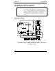
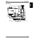
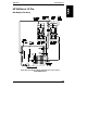
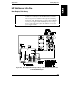
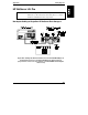
Appendix D Cabling Diagrams
156
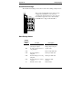
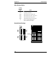
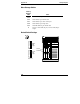
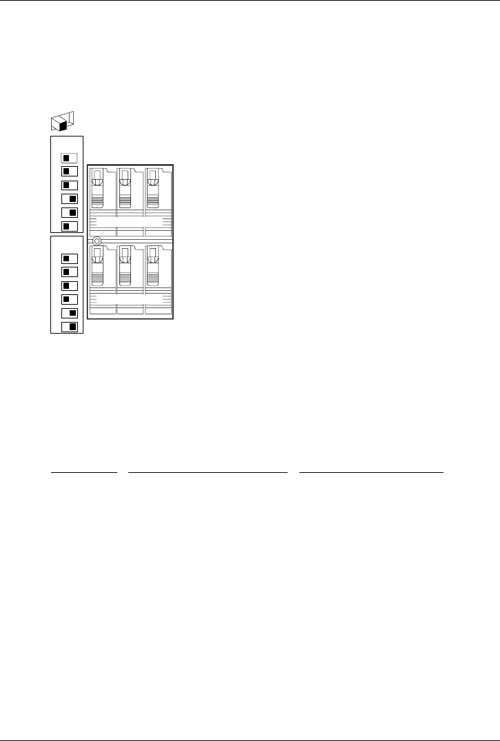
Default Switch Settings
The default switch settings are the same for both of the cabling examples shown.
UPPER
CAGE
1
2
3
4
5
6
LOWER
CAGE
1
2
3
4
5
6
6
5
4
1
0
3
SCSI ID
UPPER CAGE
LOWER CAGE
ID
ID
ID
IDID
ID
On
Off
These are the default SCSI switch settings for this
configuration. SCSI ID 2 is reserved for an
optional DAT (Digital Audio Tape) drive that can
be installed in upper drive tray 3. The standard
CD-ROM drive is shipped with SCSI ID 5.
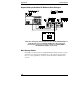
Mass Storage Cables
Cabling
Diagram
Label
Location Description
A
Internal narrow (50-pin) to
wide (68-pin) adapter
Narrow-to-Wide SCSI
adapter (50 pin to 68 pin)
B1
I
2
C cable, system board to hot
swap backplane
3-pin I
2
C cable
C11
Narrow 50-pin SCSI cable
C14
Internal backplane to
backplane
Wide 68-pin SCSI cable
C22
Internal SCSI port to hot swap
backplane
Wide 68-pin SCSI cable
C23
Internal SCSI port to external
connector
Wide 68-pin SCSI
connector
T
Built into board or cable SCSI terminator