
HP Netserver LH 4r Installation Road Map


4
If you are installing accessory cards or mass storage, remove
cover 1. If you are installing memory, remove cover 3. To install
some options, you will need a flat 1/4-inch screwdriver or a T15
TORX driver, depending on the accessory.
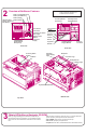
Removing and Replacing the Covers
To remove a cover:
and disconnect all power and
telephone cords.
1. Turn off the HP NetServer
WARNING Before removing cover(s), always disconnect the
power cord and unplug telephone cables.
Disconnect the power cord to avoid exposure to
high energy levels that may cause burns when
parts are short-circuited by metal objects, such as
tools or jewelry. Disconnect telephone cables to
avoid exposure to shock hazard from telephone
ringing voltages.
Note that the power switch does not turn off the
standby power. Disconnect the power cord to turn
off standby power. If the backlight on the LCD
display is on, standby power is on.
CAUTION Wear a wrist strap and use a static-dissipating work
surface connected to the chassis at all times.
Thumbscrews
Cover 1
Cover 2
Cover 3
2. Loosen the thumbscrew at the front of the cover and pull the
cover forward, using the handle on the cover, and then lift it off the
chassis.
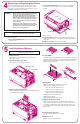
To replace a cover:
inside the cover into the slots on the chassis and
slide the side cover toward the rear. Tighten the thumbscrew at the front
of the cover.
telephone, and I/O cables.
1. Insert the tabs
2. Replace all power,
5
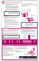
1. Remove cover 2.
Remove the cover as described in panel 4, "Removing and
Replacing the Covers."
Install Additional Memory
NOTE Use only HP DIMMs listed in HP Information
Assistant or in HP Order Assistant.
Memory Rules:
5. Replace the memory boards.
DIMMs must be installed four at a time, two per card.
DIMMs must be installed in banks, from 1 to 4.
J1 and J2 of memory A and B are bank 1.
J3 and J4 of memory A and B are bank 2.
J5 and J6 of memory A and B are bank 3.
J7 and J8 of memory A and B are bank 4.
DIMM types cannot be mixed per bank.
DIMMS are 64 or 256 MB.
DIMMs are EDO buffered TSOP at 50 ns.
Spread the two retaining clips for each socket outward. Insert each
memory board, one at a time, into its guide, and press it into its socket.
The retaining clips flip along the sides of the board when it seats. The
memory boards need to be identical, so it doesn't matter which board is
Memory A or B.
2. Open the memory cage cover.
Loosen the cover screw. Swing the cover open.
3. Remove both memory boards.
Release the latches and remove both memory boards. Place them
on a suitable anti-static surface.
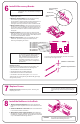
4. Install DIMMs.
Align the notches on the DIMM with the keys on the Memory board socket.
Holding the DIMM at 90 degrees to the system board, press the DIMM fully
into the socket until the retaining clips close. If the clips do not close, the
DIMM is not inserted correctly.
6. Close memory cage cover.
Swing the door shut. Tighten the cover screw.
7. Replace cover 2.
Replace cover 2 as described in panel 4.
Memory Cage
Hard Disks
Keys
Keys
Notches
Latches