HP NetServer LT 6000r Installation Guide HP Part Number D9143-90000 Printed in February 2000
Notice The information contained in this document is subject to change without notice. Hewlett-Packard makes no warranty of any kind with regard to this material, including, but not limited to, the implied warranties of merchantability and fitness for a particular purpose. Hewlett-Packard shall not be liable for errors contained herein or for incidental or consequential damages in connection with the furnishing, performance, or use of this material.
Contents 1 Setting Up the HP NetServer LT 6000r........................................................ 1 Installation Guidelines.................................................................................... 1 Rack Mount Installation ................................................................................. 2 Configuring the HP NetServer........................................................................ 4 Shipping the Fully-Configured HP NetServer ..........................................
Contents 4 Installing Mass Storage Devices............................................................... 33 Introduction ................................................................................................. 33 Tools Required ............................................................................................ 33 Mass Storage Guidelines............................................................................. 34 Integrated HP NetRAID ...................................................
Contents Configuration Guidelines.............................................................................. 68 Tools Required ............................................................................................ 68 Installing a Processor................................................................................... 68 Shutdown and Power Off the NetServer .................................................. 69 Remove the System Board Assembly ....................................................
Contents HP Management Solutions .........................................................................102 TopTools for Servers ..............................................................................102 TopTools Remote Control.......................................................................103 pcANYWHERE32...................................................................................104 NetServer Utilities..................................................................................
Contents Clearing the System Configuration..............................................................127 Password Problems....................................................................................129 13Alternative Rack Mounting.......................................................................131 Introduction ................................................................................................131 Installation Basics................................................................
Contents Service and Support ...................................................................................161 Warranty ....................................................................................................161 HP Software Product License Agreement ...................................................161 Non-Nuclear Usage ....................................................................................163 D Transporting the HP NetServer....................................................
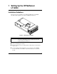
1 Setting Up the HP NetServer LT 6000r Installation Guidelines This section provides guidelines for installing the HP NetServer LT 6000r. Carefully read through this section before installing the NetServer. Figure 1-1. HP NetServer LT 6000r WARNING Do not open system board access panel while server is powered on and running. Doing so will crash system and possibly damage the NetServer. l Observe all warning and cautions. l Read this chapter before proceeding further.
Chapter 1 Setting Up the HP NetServer LT 6000r Rack Mount Installation Follow the setup steps in the exact order shown below for a successful rack installation. Skip any steps that do not apply to your installation. Figure 1-2. LT 6000r with Open Bezel 1. As you unpack the shipping container, verify its contents against the Contents List that was included with the LT 6000r. If anything is missing or damaged, call your reseller. Store the empty shipping container and packing material in a safe place.
Chapter 1 Setting Up the HP NetServer LT 6000r 3. If you have optional items to add to the NetServer, open the access panels and bezel (refer to Chapter 3, Opening and Closing the HP NetServer. If not, skip this step, and proceed to Step 8. (If you are installing accessory boards before the NetServer is mounted in the rack, remove the handles that are mounted on the accessory board access panel.) 4. If you have items, such as a processor and DIMMs, to install.
Chapter 1 Setting Up the HP NetServer LT 6000r Configuring the HP NetServer 1. Power on the monitor. Press the LT 6000r’s power button, and press the eject button on the server’s CD-ROM drive. Insert the HP NetServer Navigator CD-ROM disk, and close the drive. Press the Reset button. If the server fails to boot, follow the instructions given on the screen. Refer to Chapter 10, Configuring the HP NetServer.
Chapter 1 Setting Up the HP NetServer LT 6000r ◊ Restart the LT 6000r: a. Press [F2] when prompted. b. Press [F10] to save the configuration and exit the utility program. c. Answer "Yes" to the question: "Save the Configuration and Exit Now?" The LT 6000r will reboot, and HP Navigator will restart. NOTE The default for the LT 6000r’s integrated NetRAID is "Enabled." To disable integrated NetRAID, press [F2] to invoke the setup utility, and select "Disabled" for the Integrated NetRAID parameter.
Chapter 1 Setting Up the HP NetServer LT 6000r 13. Show System Information: Select "View System Information" to see information about accessory boards and devices. Select "View Resources" to view used and available system resources. 14.
Chapter 1 Setting Up the HP NetServer LT 6000r 15. Install HP TopTools: Refer to the HP NetServer Server Management Reference Guide, and install HP TopTools. 16. Refer to Information Assistant on the HP NetServer Online Documentation CD-ROM for more information about the LT 6000r. Also see Chapter 11, Information Assistant. 17. Test and troubleshoot as necessary. Refer to Chapter 12, Troubleshooting. Shipping the Fully-Configured HP NetServer Label each cable and component to facilitate re-assembly.
2 Controls, Indicators, and Ports Introduction Before installation, familiarize yourself with the controls, indicators, and ports described in this chapter. The human interface is at the front panel console. The network and other devices connect at the back of the chassis. Front of the Chassis Figure 2-1 shows the LT 6000r. Figure 2-1. LT 6000r Bezel and Front Panel Console NOTE A small protective cover is provided on the HP NetServer’s front bezel to cover the Power and Reset buttons.
Chapter 2 Controls, Indicators, and Ports Front Panel Console Figure 2-2 shows the LT 6000r front panel console. Figure 2-2. Front Panel Console Table 2-1. Front Panel Console Switch and Indicator Definitions Control Description Secure Mode Indicator Locks system keyboard, monitor display, and control panel to prevent unauthorized use. Go to the Setup utility security menu to configure this feature. DC Power Switch and LED Turns the HP NetServer on and off.
Chapter 2 Controls, Indicators, and Ports Control Description Resets the HP NetServer. This switch may be disabled by Secure mode. Status screen Reports system status. For details, see the following section: "Viewing System Information." Server Status LEDs Three LEDs—one red, one yellow, one green—are on the right side of the front panel console. They give you a quick idea of the HP NetServer's general health. The signals provided reflect the most critical pending event in the system.
Chapter 2 Controls, Indicators, and Ports Viewing System Information Use the NetServer’s status screen to view system configuration information or a log of current and past conditions, replaceable parts information, adjust screen contrast, and more. Use the controls to choose menus and scroll through the screens. Table 2-2 briefly describes the controls. Table 2-2. Front Panel Console Buttons Button Name Description Return to previous menu. Esc Select an item from a menu.
Chapter 2 Controls, Indicators, and Ports Table 2-3. Power Supply LED Status Green LED Steady Green NetServer Status: The system is powered up. Flashing The system is in stand-by or power-save mode. Off The AC line is unplugged or the power supply has failed (see Chapter 12, Troubleshooting). Main Menu This is the status screen default display: HP NetServer LT 6000r 1. To reach the main menu from this default screen, press the Enter button.
Chapter 2 Controls, Indicators, and Ports Event Log Menu The Event Log menu has information about current and resolved events. The menu provides a list of all events currently in the log. These may be errors, or normal system events like a system boot. 1. Select Event Log from the Main Menu. The first two lines of the log appear on the NetServer’s front panel display: ****Event Log**** >008! POST Error 2. Use the arrow buttons to see the complete list.
Chapter 2 Controls, Indicators, and Ports 10 :27 :15 Proc. 2 FRB3 Failure 4. Use the arrow keys to scroll through the entire log. 5. To return to the Event Log menu, press Escape. 6. Press Escape again to return to the Main Menu. FW Info (Firmware Information) Menu The FW Info menu displays the versions of all firmware components in the system. 1. Select FW Info from the Main Menu. A display similar to the one shown below appears on the NetServer’s front panel display. **FW Info*** 2.
Chapter 2 Controls, Indicators, and Ports 2. Use the down-arrow button to scroll through the rest of the information. A full screen of the display would appear as shown below, but the actual display is still limited by two viewing lines at time. **HW Sys Info*** No. Of CPUs=x CPU speed 500MHz CPU type P. III CPUZ stepping xx L2 Cache xxxx KB Mem slot1 xxxxMB Mem slot2 xxxxMB Mem slot3 xxxxMB Mem slot4 xxxxMB Mem slot5 xxxxMB Mem slot6.xxxxMB NOTE Z indicates the CPU number. 3.
Chapter 2 Controls, Indicators, and Ports 3. Press Escape again to return to the Main Menu. Adjust Contrast Menu This is the Adjust Contrast display. *Adjust Contrast == {XXXXXXXX}== 1. Decrease contrast by pressing or . 2. Increase contrast by pressing or . 3. To save the contrast setting, press Enter. Hard Disk Drive LED Indicators Each disk drive module has two LEDs: one for status and one for activity. You can view these LEDs on the LT 6000r with the bezel open or closed.
Chapter 2 Controls, Indicators, and Ports Indicators and Controls behind the Front Bezel The LEDs for these devices are visible only when the bezel is open or removed: l CD ROM l Flexible Disk Drive l Power Supplies Rear of the Chassis The LT 6000r’s rear panel includes communications ports, AC power receptacles, and processor fans (see Figure 2-3). In addition, all hot plug PCI slots have corresponding LED indicators located just above the PCI latch. Figure 2-3.
Chapter 2 Controls, Indicators, and Ports NOTE The management console port can be used as a second RS-232C serial port with a modem or other external device. To enable this port as a serial port, invoke the Setup Utility by pressing [F2]. Then disable Server Management (this is the management console port), and enable it as a serial port. LEDs at the Rear of the Chassis PCI Slot LEDs PCI slots 3 through 6 each have one green LED on the NetServer’s rear panel.
Chapter 2 Controls, Indicators, and Ports current at the same time. If the circuit breakers on the incoming power line have insufficient capacity, they might trip, preventing the servers from powering up. When preparing your site for installation, allow for additional inrush current. Follow these circuit breaker recommendations before installing the server at your site: • In North America, use a 20-amp-minimum circuit with one NEMA AB1 class 14B breaker for each 16-amp Power Distribution Unit (PDU).
Chapter 2 Controls, Indicators, and Ports Power Off Follow this procedure when installing non-hot-swap and non-hot-plug components, such as non-hot-plug PCI boards. 1. Log off all users and back-up files. 2. Follow instructions in your network operating system (NOS) documentation to shut down all networking software and applications. 3. Press the Power switch to shut down the NetServer. See Figure 2-3. Normally, this completes the procedure.
Chapter 2 Controls, Indicators, and Ports l The third state is the normal power shutdown. Unless the power cord is removed from the power source, all activity stops except the internal clock and the front panel LCD display. ◊ To go to a fully powered-down state, press the front panel Power switch for more than four seconds.
3 Opening and Closing the HP NetServer Introduction This chapter explains how to open the LT 6000r bezel, and how to open and close the system board and accessory board access panels. Opening the Bezel Open the LT 6000r’s bezel from the right-hand side of the server, and swing it out as shown in Figure 3-1. When you open the bezel, the power supplies, flexible disk drive, and CD-ROM drive are exposed. Bezel Figure 3-1.
Chapter 3 Opening and Closing the HP NetServer Opening and Closing the System Board Access Panel This section explains how to open and close the system board access panel that is located on the top of the LT 6000r as shown in Figure 3-2. Panel latches System board access panel Handle (in closed position) Figure 3-2. System Board Access Panel Location WARNING Always properly shutdown and power off the NetServer before you open the system board access panel.
Chapter 3 Opening and Closing the HP NetServer 1. Log off all users, and shut down the operating system according to your NOS instructions. WARNING The rack’s anti-tip foot must be extended to prevent the rack from tipping over when you slide out the NetServer. 2. Power off the NetServer. When you power off the server, the yellow LED on the system board access panel goes out. This indicates that the access panel can be safely opened. 3. Extend the anti-tip foot from the bottom of the rack.
Chapter 3 Opening and Closing the HP NetServer Figure 3-4. Rack Release WARNING Never attempt to open the system board access panel when the yellow LED is lit. Attempting to open the access panel when the LED is lit will cause the system to fail, and might damage the system board assembly and its components. 5. Before opening the system board access panel, unplug all power cords from the NetServer’s rear panel. All power cords must be unplugged before you open the system board access panel. 6.
Chapter 3 Opening and Closing the HP NetServer Figure 3-5. Open and Closed Positions on System Board Access Panel Handle 7. Slide the two panel latches toward the handle, and pull open the access panel, exposing the system board. The access panel is fully open at 90 degrees as shown in Figure 3-6. Figure 3-6.
Chapter 3 NOTE Opening and Closing the HP NetServer The system board access panel is supported by one hydraulic spring. This spring supports the weight of the system board. Closing the System Board Access Panel To close the system board access panel, perform the following steps: NOTE When properly closed, the access panel firmly seats the system board’s edge connector into the connector slot on the I/O board. 1. Close the system board access panel. 2. Ensure that the panel latches are locked in place.
Chapter 3 Opening and Closing the HP NetServer Figure 3-7. Accessory Board Access Panel WARNING Do not leave the accessory board access panel open for more than 30 minutes while the NetServer is powered on. Doing so might cause the server to overheat. To open and close the accessory board access panel, follow these steps: 1. Extend the rack’s anti-tip foot and slide out the NetServer until the slides lock. 2. Press down on the accessory board access panel latches and open the panel (see Figure 3-8).
Chapter 3 Opening and Closing the HP NetServer Figure 3-8. Opened Accessory Board Access Panel, Exposing Slots 2 through 6 3. Close the accessory board access panel. 4. Mount the server in the rack. Refer to Chapter 8, Mounting the HP NetServer in an HP Rack System/E or Rack System/U, and Chapter 13, Alternative Rack Mounting. 5. Reconnect all power cords and cables. 6. Power on the NetServer. 7. Return the NetServer to normal operation.
Chapter 3 Opening and Closing the HP NetServer Accessing PCI Slot 1 To access PCI Slot 1: 1. Shut down and power off the NetServer. 2. Disconnect all power cords and cables. 3. Remove the NetServer from the rack. NOTE Slot 1 uses a special PCI tray for installing certain accessory boards. Some accessory board require that the NetServer be dismounted from the rack in order to install the board. Certain other boards can be installed in the tray while the NetServer is mounted in the rack.
4 Installing Mass Storage Devices Introduction The LT 6000r is equipped with one hot-swap SCSI mass storage device cage that holds four low-voltage differential, low profile SCSI devices. The NetServer is also equipped with a built-in CD-ROM and a floppy diskette drive. One SCSI channel, Channel A, supports the hot-swap cage. Another SCSI channel, Channel B, supports external devices via a standard 68-pin wide SCSI connector on the rear panel.
Chapter 4 Installing Mass Storage Devices Mass Storage Guidelines Read this section before installing mass storage drives. Integrated HP NetRAID The LT 6000r contains an integrated HP NetRAID controller, which controls the HP NetRAID series of disk array controllers (DACs) in the NetServer with no additional hardware. NOTE The default for the LT 6000r’s integrated NetRAID is "Enabled.
Chapter 4 Installing Mass Storage Devices Drive Mirroring You can choose to use hardware to mirror your boot disk in the hot-swap cage (RAID Level 1). To do this you can use integrated NetRAID, and configure the NetServer appropriately. NOTE RAID Level 0, 3, or 5 also can be used with three or four drives. To configure the LT 6000r as RAID, press [F2] to enter the Setup Utility when the NetServer boots, and enable NetRAID.
Chapter 4 Installing Mass Storage Devices Hot Swap Drive Bay Addresses The hot-swap cage is addressed from left to right as ID 00, ID 01, ID 02, and ID 03 as shown in Figure 4-1. The NetServer’s default boot sequence starts at ID 00. Figure 4-2 shows the location of the external SCSI connector on the LT 6000r rear panel. ID00 ID02 ID01 ID03 Figure 4-1. Hot-Swap Cage Figure 4-2.
Chapter 4 Installing Mass Storage Devices Configuring the SCSI Host Adapter In order to verify or modify SCSI host adapter settings, or to low-level format SCSI drives or verify SCSI media, run the Symbios (SCSI) Configuration Utility. Installing Hot-Swap Mass Storage CAUTION Protect the drive from static electricity by leaving it in its anti-static bag until you are ready to install it. Before handling the drive, touch any unpainted metal surface to discharge static electricity.
Chapter 4 Installing Mass Storage Devices Locking latch (Push in, lift up, and pull out) Figure 4-3. Locking Latch Location 2. Using your fingers, pull out the filler panel. NOTE Leave the filler panels in place unless you are installing a SCSI device. They are required for proper ventilation. Figure 4-4.
Chapter 4 Installing Mass Storage Devices Readying the Drive for Installation To ready the drive for installation, press in the locking latch, and pull the ejector handle as far out as it will go. See Figure 4-5. CAUTION Be careful when you open the ejector handle. Extreme force might snap off the handle. Locking latch (pull up on ejector handle to release) Figure 4-5.
Chapter 4 Installing Mass Storage Devices Installing Hot-Swap Drives 1. Slowly slide the drive into the hot-swap cage (Figure 4-6) until it seats into its connector. CAUTION Be careful not to damage the light pipes as you insert the drive. They are very fragile. Figure 4-6. Installing a Drive into the Hot-Swap Cage 2. Press in the ejector handle until you feel the locking latch click into place. Closing the ejector handle engages the drive with the electrical connector in the hot-swap cage. 3.
Chapter 4 Installing Mass Storage Devices Removing Hot-Swap Drives CAUTION You must slowly remove the drive to ensure that the drive heads are parked prior to removal. Be sure to follow these instructions carefully to prevent damage such as head slaps or head actuator unlocking. 1. To unlock the drive, push in the locking latch, and then pull the ejector handle toward you. 2. Gently pull out the drive about an inch to disengage the power connection. 3.
5 Installing Additional Memory Introduction This chapter explains how to add memory to the HP NetServer LT 6000r. The NetServer is shipped from the factory with 256 MB of interleaved memory: one 128 MB DIMM in socket 1A, and one 128 MB DIMM in socket 1B. Expansion is accomplished by adding pairs of equal size DIMMs in the appropriate sockets. Up to 8 GB of memory can be installed in the NetServer. Figure 5-1.
Chapter 5 Installing Additional Memory l Memory can be added in pairs in any order to the three remaining socket pairs. • Do not rock the DIMM into its socket. Apply firm and even pressure until the DIMM is seated in the socket. l Use only HP-supported DIMMs. Tools Required The following tools are required for DIMM removal and installation: l An antistatic service kit (3M 8501/8502/8503 or equivalent). This kit includes a static-dissipating work surface, a chassis clip lead, and a wrist strap.
Chapter 5 Installing Additional Memory WARNING Always disconnect the power cords before opening the system board access panel to avoid exposure to high energy levels that might damage equipment or cause personal injury. Disconnect any telephone cables to avoid exposure to shock hazard from telephone ringing voltages. 6. Identify the socket locations for the DIMM pairs according to the following table: Table 5-1.
Chapter 5 Installing Additional Memory DIMM Retaining Clip Notches Keys Retaining Clip Figure 5-2. Inserting a DIMM into Its Socket e. Holding the DIMM 90 degrees to the system board, press the DIMM into the socket until the retaining clips close. If the clips do not close, the DIMM is not inserted correctly. CAUTION Do not rock the DIMM into its socket. Apply firm and even pressure. It a gap exists between the retaining latches and the DIMM, remove and replace the DIMM until no gap exists. 8.
Chapter 5 Installing Additional Memory 2. Power off the NetServer according to instruction in Chapter 2, Controls, Indicators, and Ports. WARNING The power supply will continue to provide standby current to the NetServer. 3. Slide out the server from the rack. CAUTION The power supply will continue to provide standby current to the NetServer. 4. Disconnect the power cords and cables and, if necessary, label each one to support reassembly. 5. Slide out the NetServer from the rack. 6.
6 Installing Additional Boards Introduction This chapter explains how to install PCI accessory boards into the HP NetServer LT 6000r PCI slots. The PCI slots are located on the I/O baseboard behind the accessory board access panel as shown in Figure 6-1. Figure 6-1. Accessory Board Access Panel The LT 6000r I/O board accommodates six PCI accessory boards. Each slot supports standard PCI boards; Slots 3, 4, 5, and 6 support the Hot-Plug option.
Chapter 6 Installing Additional Boards Figure 6-2. PCI Accessory Board Slots The I/O baseboard consists of the following components: l Six PCI accessory board slots l PCI slot Hot-Plug LEDs l I2O memory slot, which contain cache memory DIMM used by the embedded RAID controller (Intel i960RN I/O processor); which is 64 MB standard and can be upgraded to 128 MB.
Chapter 6 Installing Additional Boards • Use the appropriate NOS utility for the following: ◊ To ensure that the correct PCI accessory board software drivers are installed. ◊ To verify that the board is operating correctly. • Slots 1 and 2 are used only for non-hot-plug accessory boards. • Slots 3, 4, 5, and 6, are used for hot-plug accessory boards. If non-hot-plug supported boards are installed in these slots, the hot-plug feature is disabled.
Chapter 6 Installing Additional Boards Tools Required l Torx 15 driver • An antistatic service kit (3M 8501/8502/8503 or equivalent). This kit includes a static-dissipating work surface, a chassis clip lead, and a wrist strap. IRQ Settings The BIOS automatically assigns hardware interrupts (IRQs) for each PCI slot and embedded device installed in the NetServer during the boot sequence. These assignments trigger the NOS to enable the Advanced Programmable Interrupt Controller (APIC).
Chapter 6 Installing Additional Boards For current PCI Hot-Plug information about NOS support and the availability of PCI Hot-Plug compliant drivers, search for pcihotplug on HP’s website at: http://www.hp.com/netserver/products/LT 6000r Installing Accessory Boards NOTE To perform a hot add or a hot replacement when the HP NetServer is powered on, refer to help information provided on the HP NetServer Navigator CD-ROM provided with your HP NetServer.
Chapter 6 WARNING Installing Additional Boards Always power off the PCI slot before opening the slot latch when an accessory board is installed in the slot. Failure to power off the slot before opening the latch might crash or damage the system. 1. Log off users, and shut down the NetServer according to your NOS instructions. 2. Power off the NetServer. 3. Disconnect the power cords and cables and, if necessary, label each one to support reassembly.
Chapter 6 Installing Additional Boards Figure 6-3. Removing the PCI Slot Cover (Locking Levers and Retainers Shown) 8. Before installing an accessory board: ◊ Verify that there is no extender attached to it, especially if it is a full-length board. ◊ If the board has a extender attached to it, remove the extender before installing the board. 9. Align the full length of the board with its slot and position it into the slot.
Chapter 6 Installing Additional Boards Figure 6-4. Installing the Accessory Board 10. Push the accessory board’s edge connector into the slot’s connector. 11. Close the retainer. 12. Secure the accessory board by rotating the locking lever counter-clockwise to the hold the retainer. 13. Close the accessory board access panel. 14. If the installed accessory board requires an external connection or a connection to the I/O board, ensure that the cable is properly connected.
Chapter 6 Installing Additional Boards 17. Use the respective NOS to ensure that the correct PCI board software drivers are loaded, and verify its correct operation. 18. Restore the NetServer to normal operation. Installing an Accessory Board in Slot 1 This section explains how to install a PCI accessory board in Slot 1 via the installed accessory board tray. This tray is used specifically for installing a board in Slot 1 when the NetServer is mounted in a rack.
Chapter 6 Installing Additional Boards Case 1: The accessory board can be installed in the tray while the NetServer is mounted in the rack. Case 2: The accessory board can only be installed in the tray while the NetServer is not mounted in the rack. Case 3: The accessory board is not installed in the tray, and the NetServer is not mounted in the rack. CAUTION * There is no support in Slot 1 for the "free" or hanging end of the accessory board.
Chapter 6 Installing Additional Boards NOTE For Case 1 (from Table 6-1), the NetServer can remain installed in the rack. For Cases 2 and 3, the NetServer must be removed from the rack, and you must remove both slides from the chassis before you can open the access panel. NOTE It is recommended to remove the NetServer from the rack before installing a full-size accessory board in the accessory board tray. NOTE Read label on accessory board access panel before installing the board.
Chapter 6 Installing Additional Boards When seating a Half-size, half-height board into its slot, push in the board here with one hand. Half-size accessory board edge fits under this tang. Half-size, half-height accessory board While pushing in the board with one hand, push in the tray with the other. Figure 6-6.
Chapter 6 Installing Additional Boards Ensure that this side of the tray is aligned with the left-hand metal guide inside the chassis. Ensure that this side of the tray is aligned with the right-hand metal guide inside the chassis. Ensure that lower door is open when inserting tray and accessory board. Figure 6-7.
Chapter 6 Installing Additional Boards Accessory board (full-size) edge fits under these tangs. After seating the board in the tray, push the tray into the chassis so that the board’s edge connector inserts into the slot. Figure 6-8. Seating the Accessory Board into Tray (Full-Size Board) 8. Slide the tray into the slot so that the board’s edge connector is pushed into the slot connector on the I/O board. 9. Close the retainer over the slot cover (see Figure 6-9). 10.
Chapter 6 Installing Additional Boards Figure 6-9. Locking Lever and Retainer Close-Up 11. Close the accessory board access panel. 12. If the installed accessory board requires an external connection or a connection to the I/O board, ensure that the cable is properly connected. Refer to the documentation that came with the accessory board for instructions. 13. Reconnect the power cords and cables. 14. Power on the NetServer and restart the network operating system, according to your NOS instructions.
Chapter 6 NOTE Installing Additional Boards All PCI slots power on when the locking levers are closed, and the HP NetServer recognizes all new boards when it reboots, regardless of the presence of a driver or a PCI Hot-Plug Utility. If the PCI accessory board requires a driver (non-hot-plugcompliant or hot-plug compliant) that is not loaded during NOS installation, you must load the driver according to the respective NOS driver installation process before you can use the board.
Chapter 6 Installing Additional Boards 3. Scroll down the list, and select NetServer LT 6000r. 4. Select Install. 5. Select Installing Accessory Boards. 6. Select the appropriate Hot-Plug Replacement topic. NOTE To perform a hot add or a hot replacement when the NetServer is powered on, refer to the PCI Hot-Plug Help file on the HP NetServer Navigator CD-ROM. Removing a Hot-Plug Accessory Board To remove a hot-plug board from the NetServer, which is not powered on, follow these instructions: 1.
7 Installing Additional Processors Introduction The LT 6000r comes equipped with one primary processor module and one corresponding voltage regulator module (VRM) installed on the system board assembly. Up to five additional processors and corresponding VRMs can be added. All processor modules must operate at the same clock frequency and cache size. Figure 7-1.
Chapter 7 Installing Additional Processors NOTE The processor upgrade kit includes the HP NetServer Navigator CD-ROM. After installing processors, boot with this CD-ROM to update the BIOS. Configuration Guidelines Use the following guidelines when installing additional processor modules in the LT 6000r: • Use only processor module upgrade kits with the same HP product number.
Chapter 7 CAUTION Installing Additional Processors Do not remove the processor from its bag until you are ready to install it. Make sure that the bag remains sealed. Shutdown and Power Off the NetServer 1. Log off users and shut down the NetServer according to your NOS instructions. 2. Power off the NetServer. 3. Disconnect the power cord and cables from the NetServer’s rear panel and label them for reassembly.
Chapter 7 Installing Additional Processors Figure 7-2. Release Latch Locations 70 CAUTION The system board assembly is heavy. Use the two handles on each side of the top processor cover to lift the system board from the NetServer chassis. CAUTION Wear a wrist strap and use a static-dissipating work surface connected to the chassis when handling components.
Chapter 7 Installing Additional Processors 3. Use the handles located on the top processor cover to lift the system board assembly from the NetServer chassis. Figure 7-3. Removing the System Board Assembly from the Access Panel 4. Place the assembly on an antistatic pad. 5. Unpack the processor shipping box and check the contents against the packing list.
Chapter 7 Installing Additional Processors Install the Processor 1. Loosen the thumbscrew and remove the access cover on the processor cage. Figure 7-4. Loosen Thumbscrew on Processor Cage Access Cover 2. Locate the slot where you will install the new processor, open the latches on the terminator board, and remove it from the slot. 3. Remove the new processor from its bag. 4. Open the latches on the new processor.
Chapter 7 Installing Additional Processors Figure 7-5. Opening the Latches and Installing the Processor 5. Align the processor over the open slot so that the heat sink faces up for Slots 1, 2, and 3; and down for Slots 4, 5, and 6. 6. Slide the processor into the slot until it’s fully seated. 7. Close the latches to seat the processor firmly into its connector. 8. Replace the processor cage access cover, and tighten the thumbscrew. 9.
Chapter 7 Installing Additional Processors Figure 7-6. Installing a VRM CAUTION Do not touch the VRM components as you push it into its slot. Replace the System Board Assembly 1. Insert the system board assembly into the system board access panel, and ensure that the release latches snap completely closed. Ensure that the latches are closed by pressing inward on them. 2. Close the system board access panel according to the instructions in Chapter 3, Opening and Closing the HP NetServer. 3.
Chapter 7 Installing Additional Processors Setting the Processor Speed Processor speeds are set from the system switch located on the system board. NOTE Some processor speeds may not be supported. For latest information, visit the HP website: http://www.hp.com/go/netserver Figure 7-7. System Switch Location Determine the processor speed from the following table, and set the system switch accordingly. Table 7-1.
Chapter 7 Installing Additional Processors Upgrading the Firmware Load the HP NetServer Navigator CD-ROM and power on the LT 6000r. Perform the following instructions to ensure that the BIOS is up-to-date. NOTE You are not required to use the HP NetServer Navigator CD-ROM to reconfigure your system after installing the new processor. The NetServer detects additional processors automatically.
8 Mounting the HP NetServer in an HP Rack System/E or Rack System/U Introduction This chapter tells how to mount the HP NetServer LT 6000r in an HP Systems rack. Figure 8-1.
Chapter 8 Mounting the HP NetServer in an HP Rack System/E or Rack System/U NOTE If you have the older HP Systems rack, refer to Chapter 13, Alternative Rack Mounting. If you are mounting the server in a non-HP rack, see the documentation in the non-HP rack accessory kit. The LT 6000r requires four EIA units of space in the rack. Before mounting the server, plan the server’s location in the rack relative to other rack components. Proper placement is vital for safety and operating efficiency.
Chapter 8 Mounting the HP NetServer in an HP Rack System/E or Rack System/U room’s ambient temperature. Make sure that the temperature within the rack does not exceed 35°C (95°F). • Reduced Air Flow. As you mount equipment in the rack, make sure that you allow enough air flow for safe operation of the equipment. • Mechanical Loading. Uneven mechanical loading within the rack can cause hazardous conditions. Plan the placement of equipment in the rack to make sure that this problem does not occur.
Chapter 8 Mounting the HP NetServer in an HP Rack System/E or Rack System/U System, see Chapter 13, Alternative Rack Mounting, for alternative rack mount instructions. NOTE Use the HP Rack Assistant software to determine where to mount the HP NetServer in the rack. CAUTION To ensure rack stability, always mount rack components from the bottom up. 1. Pull the anti-tip foot out of the bottom of the rack (see Figure 8-2). Figure 8-2. Anti-Tip Foot 2.
Chapter 8 Mounting the HP NetServer in an HP Rack System/E or Rack System/U server requires.) The template directs you to the second and fourth holes on the rack column that are used for mounting the slide. Mark these holes from the baseline (bottom) for future reference. 3. Hold the template against the front face of the left-rear rack column (as you are looking from behind the rack). The template directs you to second and fourth holes in the rack column. Mark them from the baseline for future reference.
Chapter 8 Mounting the HP NetServer in an HP Rack System/E or Rack System/U 1. Loosen the adjustment knob on one slide, insert the rear rack pins into the appropriate holes on the outside rear column, and hold into position. 2. While holding the slide in the rack, extend the front bracket forward to the outside front column using the grip on the slide, and insert the front rack pins into the holes that you marked with the template. See Figure 8-4. Figure 8-4. Insert Rack Pins into Rack 3.
Chapter 8 Mounting the HP NetServer in an HP Rack System/E or Rack System/U Step 3: Mount the LT 6000r in the Rack This step explains how to mount the LT 6000r into the rack. WARNING Ensure that the rack’s anti-tip foot is fully extended out of the rack to prevent rack instability while mounting LT 6000r. Failure to do so could result in injury and equipment damage.
Chapter 8 Mounting the HP NetServer in an HP Rack System/E or Rack System/U 2. With the help of at least one other person, lift the server by its four handles, and position it directly over the extended slides. NOTE The arrows on the sides of the LT 6000r must line up with the slide’s mounting hooks before you lower the server onto the slides. These hooks fit inside the server as you lower it onto the slides. WARNING The LT 6000r weighs up to 100 lbs (45 kgs).
Chapter 8 Mounting the HP NetServer in an HP Rack System/E or Rack System/U 4. Pull the LT 6000r forward onto the slides until the nib on the blue latch snaps into the square hole on the slide. This ensures that the mounting hooks are properly seated inside the chassis, and that the server is locked into position on the slides (see Figure 8-7). Figure 8-7. Latch Nib Inside Square Hole on Slide (View with Bezel Removed) 5. Remove the four handles from the sides of the chassis. See Figure 8-8.
Chapter 8 Mounting the HP NetServer in an HP Rack System/E or Rack System/U Figure 8-8. Removing the Handles 6. Release the slide locks, and push the mounted server into the rack. The server will lock into place. Push the server to the first notch on the blue rack latch position closest to the bezel (see Figures 8-9 and 8-10). The second latch position is used when mounting the HP NetServer in a non-HP rack. WARNING 86 Do not slide the NetServer into rack when the bezel is in the closed position.
Chapter 8 Mounting the HP NetServer in an HP Rack System/E or Rack System/U Figure 8-9. Release the Slide Lock Figure 8-10.
Chapter 8 Mounting the HP NetServer in an HP Rack System/E or Rack System/U 7. Open the bezel, and turn the key lock on the right-hand side of the LT 6000r’s front panel to prevent the server from being released from the rack. 8. Close the bezel. 9. Refer to the Rack Mount Cabling Reference Guide on the HP NetServer Navigator CD-ROM for information about installing the LT 6000r’s Cabling Management Arm and other cabling instructions.
Chapter 8 Mounting the HP NetServer in an HP Rack System/E or Rack System/U Figure 8-12. Installing the Cable Management Arm to the NetServer Rear Panel 2. Install the rack bracket to the left-hand rear column on the rack as shown in Figure 8-13. The bracket’s position should be in line with the chassis bracket. a. Use the template to locate and mark the two holes for installing the rack nuts. b. Install two rack nuts and two M5 screws to the left-hand rear column.
Chapter 8 Mounting the HP NetServer in an HP Rack System/E or Rack System/U Figure 8-13. Installing the Cable Management Arm to the Left-Hand Rack Column 3. Refer to the LT 6000r Rack Assembly and Cabling Reference Guide on the HP NetServer Navigator CD-ROM for information about cable routing.
9 Connecting the Monitor, Keyboard, and Mouse Introduction This chapter explains how to connect a monitor, keyboard, mouse, and uninterruptible power supply (UPS) to the HP NetServer LT 6000r. Connecting the Monitor, Keyboard, Mouse, and UPS To connect the monitor, keyboard, mouse, and UPS to the NetServer, follow these steps: 1. Connect the monitor, keyboard, and mouse to the NetServer. See Figure 9-1 for port locations.
Chapter 9 Connecting the Monitor, Keyboard, and Mouse Figure 9-1. HP NetServer LT 6000r Ports NOTE If you have a console switch box, refer to the switch box’s user guide for instructions on connecting the monitor, keyboard, and mouse. 2. Connect each of the power supply module’s power cords to the power receptacles on the rear panel. 3. If you have a UPS installed in the rack, power on the device. Use the supplied serial cable to connect the UPS to the HP NetServer.
10 Configuring the HP NetServer Introduction This chapter describes the following: l Configuring the HP NetServer l Installing the Network Operating System (NOS) NOTE The HP NetServer ships with NetRAID as the default. If you plan to configure mass storage as LVD SCSI, change the default using the Setup Utility prior to installing the NOS. HP NetServer Navigator CD-ROM Use the HP NetServer Navigator CD-ROM (Navigator) to perform configuration tasks or view online system documentation.
Chapter 10 Configuring the HP NetServer 2. Choose the model of your HP NetServer. 3. Choose the desired NOS to be configured on your NetServer. 4. Review "What’s New on the CD." You can save the text to a flexible diskette and print the information for future reference. 5. Review "System README." This file provides up-to-date system information that was not available at the time the documentation was published. You can save the text to a flexible diskette and print the information for future reference. 6.
Chapter 10 Configuring the HP NetServer l Part number of the HP NetServer Navigator CD-ROM l Document Number Status Report The Status Report for your specific HP NetServer Navigator CD-ROM describes in detail any software updates between this version of the CD-ROM and the previous version. To obtain Release Notes or a Status Report, go to: http://netserver.hp.com/netserver/support/compatibility /nav_cd/navigator.
Chapter 10 NOTE Configuring the HP NetServer Using the low profile CD-ROM drive is slightly different from full-height units. The disk drawer will spring out only part way when you press the eject button. You must manually open and close the drawer. 4. If the CD-ROM fails to autorun, follow the diagnostic instructions on the screen. 5. Go to the HP Navigator main menu. NOTE If this is the first time you are using the Navigator, you are prompted to set the language, time, and date.
Chapter 10 Configuring the HP NetServer Configuration Assistant and Information Assistant Configuration Assistant guides you through the steps necessary to configure the HP NetServer. You can view configuration advisories, and change your hardware if necessary. Three methods of configuration are available: Express, Custom, and Replicate. Installation Assistant guides you through the NOS installation, and configures the NOS with the appropriate drivers.
Chapter 10 Configuring the HP NetServer l Select NOS: You will be asked to select the NOS and version you plan to install. l Select NOS Installation Mode: For certain versions of Novell NetWare/IntranetWare and Microsoft Windows NT Server, you will be asked: Would you like to use HP’s automated mode of NOS installation? ◊ Select Yes for automated NOS installation.
Chapter 10 Configuring the HP NetServer l Configure Remote Management: This utility configures the Integrated Remote Management device for remote management. It enables remote dial-up HP NetServer management. To configure Integrated Remote Assistant, select Configure Remote Management on the Configure Remote Management screen. l Show System Information: Use this screen to display information about standard and accessory boards and devices in the system, as well as the used and available system resources.
Chapter 10 Configuring the HP NetServer l Execute Card Utilities: Use this function when Configuration Assistant detects installed boards that have additional configuration utilities on the HP NetServer Navigator CD-ROM. By selecting Execute on the Execute Board Utilities screen, you can execute these utilities to complete the configuration of the boards.
Chapter 10 Configuring the HP NetServer Recommended Steps l Update System BIOS: This utility updates the system BIOS. The utility partition, if installed, will also be updated. l Install/Update Utility Partition: Installs utility partition to the boot or system drive. This is not available under SCO UnixWare. l Show System Information: Shows hardware inventory and system resource (interrupts, I/O space) allocation.
Chapter 10 Configuring the HP NetServer l For Manual NOS Installation: Before you perform a manual NOS installation, you must manually create NOS-specific driver diskettes, and print instructions as follows: ◊ Create Drivers Diskette(s): On the Create Drivers Diskette(s) screen, select Create Drivers Diskette(s) to create one or more customized diskettes containing HP drivers and configuration files to use when you install the NOS.
Chapter 10 Configuring the HP NetServer TopTools features include: l Notification of problems with key hardware components, including memory, disk drives, SCSI controllers, NICs, and power supplies, as well as problems with temperature and voltage. l Unified event log to review a complete history of HP NetServer activity. l Predictive disk problem warning backed by HP pre-failure warranty replacement. l Disk capacity threshold alert and usage tracking.
Chapter 10 Configuring the HP NetServer l The event log. l Server reset and power control. l Remote system BIOS or TopTools Remote Control update. l Password and dial-back security. l Text console redirection of the HP NetServer console. l Full graphics console redirection of Microsoft Windows NT Servers across the network or over a modem connection using Symantec’s pcANYWHERE32 software (included with the system). See the HP TopTools Remote Control User Guide for details.
Chapter 10 Configuring the HP NetServer l Print or View Information: Lets you print or view the current system configuration, including details of boards that are detected in the system, and resources that are allocated to the boards. l Change User Preferences: Lets you change the language used by the HP NetServer Navigator CD-ROM and the system date and time. Setup Utility The HP NetServer has a setup utility (BIOS) in read-only memory.
Chapter 10 Configuring the HP NetServer and disabling HotADD Reserved Resources. Configuring the multi-processor (MP Specification Version) feature is done from here, too. ◊ Boot Setting: Use this menu to check the flexible disk drive, display the NetServer’s configuration at boot time, skip certain tests during the boot process to speed up boot time, or change the (default) boot order, including device type, network boot, and hard disk drive boot order.
Chapter 10 Configuring the HP NetServer Using the Setup Screens Online help explains the settings displayed on the Setup Utility screens. Instructions are also provided for navigating between the screens, and entering or changing the setup data. l Press the right-arrow and left-arrow keys to move between selections on the menu bar. The menu bar is present at the top of the main selections. l Press the up-arrow and down-arrow keys to move between fields on each screen.
Chapter 10 Configuring the HP NetServer 5. Type in the minutes, and press Enter to move to the seconds field. 6. Type in the seconds, and press Enter and use the arrow keys to leave this field. 7. Use the up and down-arrow keys to scroll to the System Date field, and enter the system date in the field. The dates are entered in the System Date field in the same way as the time is entered in the System Time field.
Chapter 10 Configuring the HP NetServer 3. If necessary, use the arrow keys to move to the Power-On Password menu selection, and press Enter. The Power-On Password is highlighted by default when the Security menu is selected. The first line in the menu, "Administrator Password is [Set or Not Set]": ◊ If no password has been set, then "Not Set" appears in the field. If this is the case, you are not allowed to make any selections in this menu until you set an administrator password.
Chapter 10 Configuring the HP NetServer 8. Choose "Yes," and press Enter. The "Administrator Password is" field changes to "Set," and the next time you boot the server, you will be prompted for the password to access the Setup Utility. 9. If you want a password on boot up, you can skip the "User Password is" field, and go directly to Network Server Mode in Step 11. 10. If you want to enter a user password, use the arrow keys to move to the "User Password is" field, and repeat Steps 3 through 7. 11.
Chapter 10 Configuring the HP NetServer 21. To change one of the passwords at a future date, return to the Security menu, and repeat Steps 3 through 7. NOTE The HP NetServer lets you reset the password by toggling Switch 6 on the system switch that is located on the system board. Changing Internal Device Boot Priority You can change the boot priority of the HP NetServer’s internal mass storage devices. To do this, follow these instructions: 1.
Chapter 10 Configuring the HP NetServer 1. 2. 3. [Bootable Cards] [#30 ID01 LUN0 HP [#30 ID01 LUN0 HP 4.2GB A] 4.2GB A] The server attempts to boot the NOS on the first hard drive (or DAC or SCSI board) found in the list. If no NOS is found, the system tries to boot from the next hard drive in the list until a NOS is found. 6. Use the plus (+) or minus (-) key to move the desired hard drive to the top of the list. ◊ The hard drive boot list has a maximum capacity of 8 logical drives.
Chapter 10 Configuring the HP NetServer Figure 10-2. System Board Configuration Switch 3. Close the system board access panel and power on the server. 4. Let the server boot. 5. After booting, shut down and power off the server and open the system board access panel. 6. Reset Switch 5 from the ON position to OFF. 7. Close the system board access panel and power on the server.
Chapter 10 Configuring the HP NetServer 3. Use the arrow keys to move the cursor, press Enter to select an option, and press Esc to exit. 4. To change adapter settings: ◊ Select an adapter from the list in the main menu. ◊ Select "Adapter Setup." This option configures the SCSI ID settings, and other advanced adapter settings. 5. To format a hard disk or change hard disk parameters: ◊ Select an adapter from the list in the main menu. ◊ Select "Drive Selections." ◊ Select the hard disk to format.
11 Information Assistant Introduction The HP NetServer Online Documentation CD-ROM includes "Information Assistant," which contains the entire set of documentation for your HP NetServer.
Chapter 11 Information Assistant NetServer E Series This menu button provides access to the individual NetServer E Series products. Typical topics provided for each product model are: l Install l Configure l Fix l Server Management l Accessories l Reference Topics l Glossary NetServer L Series This menu button provides access to the individual NetServer L Series products. Typical topics provided for each product model are the same as identified for the E Series products.
Chapter 11 Information Assistant Server Management This menu button provides access to various NetServer management products. Representative topics are: l HP TopTools l HP TopTools Remote Control l HP NetServer Assistant l HP OpenView Informational files about some of these products are provided as Adobe Acrobat (.pdf) files. NOTE In order to launch and display Adobe Acrobat (.pdf) files from HP NetServer Information Assistant, you will need to have a .pdf file viewer installed on your system.
Chapter 11 Information Assistant Finding Information Information Assistant provides many ways to navigate through its topics and locate information. For example, you can: Select a topic from the Map. Displays a window with an outline of every module and topic in Information Assistant for the selected product. The Map enables you to view the contents of the Information Assistant in outline format, and to then select a topic. Search for a word or phrase using Search.
Chapter 11 Information Assistant You can also navigate between topics by using hot spots and by using the History button to revisit previously viewed topics. For example: • Jump to other topics. Click on hot spots in graphics and text that link to other topics or to more information about the current topic. Hot spot text appears as bold green text. Identify hot spots on graphics by moving the pointer over the graphic. When you point to a hot spot, the pointer changes to a hand.
Chapter 11 Information Assistant Installing from the CD-ROM This is a 16-bit Windows application that can be run on Windows 3.1 and above. If you are using Windows 95/98 or Windows NT, and have the AUTORUN feature of your CD-ROM drive enabled, it will automatically start the setup program. If you have previously installed this new version of HP NetServer Information Assistant on your system, it will automatically launch the program.
12 Troubleshooting Troubleshooting Tools If you are having problems installing your HP NetServer, there are a number of different tools available for troubleshooting: • HP NetServer Information Assistant (see Chapter 11) contains the following tools: ◊ Troubleshooting Information ◊ Part Information ◊ List of Error Messages and Beep Error Messages • The HP NetServer Navigator CD-ROM contains HP NetServer Utilities: At the HP NetServer Navigator Main Menu, select "Access NetServer Utilities" to use the
Chapter 12 Troubleshooting • For problems with HP TopTools, refer to the HP TopTools Administrator Guide on the HP Web Site at: http://www.hp.com/toptools • For general information on management products, refer to: http://www.hp.com/go/netserver_mgmt and search for "management." Common Installation Problems The following sections contain general procedures to help you locate installation problems. If you need assistance, it is recommended that you contact your reseller first.
Chapter 12 Troubleshooting • Unplug the power cord, wait 20 seconds, plug the power cord in again, and restart the NetServer. • If you suspect a hardware error, follow these steps: a. Log users off the LAN and power down the server. b. Extend the HP NetServer out of the rack. c. Simplify the HP NetServer configuration to the minimum required: • Monitor • Keyboard • Mouse • 1 hard disk drive and 1 flexible disk drive • 1 flexible, and one hard disk drive • 1 CD-ROM d.
Chapter 12 Troubleshooting 6. Ensure that the system board access panel is properly closed with the handle in the closed position, and that the yellow LED is on. 7. Ensure that all processors and VRMs are properly installed. 8. Clear CMOS. 9. Perform a BIOS recovery. If the System Powers On, but Fails POST Do one of the following: • If the system gives a series of beeps, this indicates a system error. Ensure that all DIMMs are properly installed in their sockets or contact HP or your reseller.
Chapter 12 Troubleshooting d. Verify that the DIMMs are firmly seated on the system board. Verify that added DIMMs are HP DIMMs. e. Close the access panels and lock the system. f. Replace all power cords and cables. g. Power on the monitor. h. Power on the server. i. Check for error messages. 4. Copy DiagTools from the HP NetServer Navigator CD-ROM to diskette and run it from diskette. 5. Invoke the Event Log Report Utility from the NetServer Utility to display all reported errors.
Chapter 12 Troubleshooting DiagTools You can create your own diskette of tools to diagnose components offline. A basic suite of tools checks key HP NetServer components, and a menu of advanced tests is available for in-depth testing. DiagTools does not use any tests, which might write over and destroy user data. The advanced series requires user input, and decisions are left to the advanced series.
Chapter 12 Troubleshooting If you have TopTools remote management software installed and configured for use with DiagTools, you can accomplish any of the above tasks remotely. See the online documentation HP NetServer DiagTools Error Reference and User Guide for more information on DiagTools. Error Messages All errors are localized in the BIOS and displayed in POST.
Chapter 12 Troubleshooting Figure 12-1. System Switch Settings 6. Close the system board access panel, plug in the power cords, and power on the HP NetServer. The following message appears. This configuration has been cleared. Set the Clear Config switch to the OFF position before rebooting. 7. Power off the server, disconnect the power cords, and open the system board access panel. 8. Return Switch 5 to the OFF position. 9. Close the system board access panel and reconnect the power cords and cables.
Chapter 12 Troubleshooting Password Problems If you have forgotten the password, your HP NetServer will function normally, but you will not be able to change the system configuration settings in the setup utility. To reset the password, follow these instructions: 1. Log off all users and shut down the network operating system according to directions in your NOS documentation. 2. Power off the server according to the instructions in Chapter 2, Controls, Indicators, and Ports. 3.
13 Alternative Rack Mounting Introduction This chapter tells how to mount the HP NetServer LT 6000r in an HP System Rack. a b c d a. 3-cornered columns b. Fan-only vent c. “HP Systems” name plate d. EIA units marked by triangles e. Anti-tip foot extends out front only e Figure 13-1.
Chapter 13 Alternative Rack Mounting NOTE If you have the newer HP Rack System/E or HP Rack System/U rack, refer to Chapter 8, Mounting the HP NetServer in an HP Rack System/E or Rack System/U. If you are mounting the server in a non-HP rack, see the documentation in the non-HP rack accessory kit. The LT 6000r requires four EIA units of space in the rack. Before mounting the server, plan the server’s location in the rack relative to other rack components.
Chapter 13 Alternative Rack Mounting room’s ambient temperature. Make sure that the temperature within the rack does not exceed 35°C (95°F). • Reduced Air Flow. As you mount equipment in the rack, make sure that you allow enough air flow for safe operation of the equipment. • Mechanical Loading. Uneven mechanical loading within the rack can cause hazardous conditions. Plan the placement of equipment in the rack to make sure that this problem does not occur.
Chapter 13 Alternative Rack Mounting Step 1: Mark the LT 6000r’s Position in the Rack Use the rack-mount template to mark out four EIA units for positioning the LT 6000r in the rack. NOTE Use the HP Rack Assistant software to determine where to mount the HP NetServer in the rack. CAUTION Be sure to compensate for any other components that might be mounted in the rack. Install these components before mounting the LT 6000r. 1. Pull the anti-tip foot out of the bottom of the rack. Figure 13-2.
Chapter 13 Alternative Rack Mounting 2. Hold the template alongside the inside face of the left-front rack column. Line up the template with the same rack space that the server will occupy. (The template covers an area four EIA units high, the same height the server requires.) The template directs you to two holes in the rack column that are used for mounting the slide. Mark the second and third holes from the baseline (bottom) future reference. 3.
Chapter 13 Alternative Rack Mounting 3. Remove the lock nuts that secure the slide brackets to the slide. You will need two of these nuts from each slide to secure the slides to the inside columns of the rack. Store the other nuts as you did in Step 2. Step 3: Install the Slides in the Rack This step explains how to install the LT 6000r slides in the rack. Refer to Figure 13-4 during the installation. Figure 13-4. Slides Ready for Installation 1.
Chapter 13 Alternative Rack Mounting Figure 13-5. Installing the Slides in the Rack NOTE To differentiate between both slides, the right-hand slide is marked with an R embossed on the outside; the left-hand slide is marked with an L. Arrows pointed up are embossed on the outside of each slide to show the correct orientation. 2. Use the lock nuts to secure the slides to the rack by screwing them onto the threaded pin. These are the same nuts you put aside when you dismantled the slides.
Chapter 13 Alternative Rack Mounting Step 4: Mount the LT 6000r in the Rack This step explains how to mount the LT 6000r onto its slides in the rack. WARNING Ensure that the rack’s anti-tip foot is fully extended out of the rack to prevent rack instability while mounting LT 6000r. Failure to do so could result in injury and equipment damage.
Chapter 13 Alternative Rack Mounting 2. With the help of at least one other person, lift the server by its four handles, and position it directly over the extended slides (see Figure 13-7). Figure 13-7. Mounting the NetServer NOTE The arrows embossed on the sides of the LT 6000r must line up with the slide’s mounting hooks before you lower the server onto the slides. These hooks fit inside the server as you lower it onto the slides. WARNING The LT 6000r weighs up to 100 lbs (45 kgs).
Chapter 13 Alternative Rack Mounting 4. Pull the LT 6000r forward onto the slides until the nib on the blue latch snaps into the square hole on the slide members. This ensures that the mounting hooks are properly seated inside the chassis, and that the server is locked into position on the slides. Figure 13-8. Latch Nib Inside Square Hole on Slide (View with Bezel Removed) 5. Remove the four handles from the sides of the chassis. See Figure 13-9.
Chapter 13 Alternative Rack Mounting Figure 13-9. Removing the Mounting Handles 6. Release the slide locks and push the mounted server into the rack. The server will lock into place. Push the server to the first notch on the blue rack latch position (see Figures 13-10 and 13-11). The second latch position is used when mounting the HP NetServer in a non-HP rack. WARNING Do not slide the NetServer into rack when the bezel is in the closed position.
Chapter 13 Alternative Rack Mounting Figure 13-10.
Chapter 13 Alternative Rack Mounting Figure 13-11. Rack Latch Close-Up (View with Bezel Removed) 7. Open the bezel and turn the key lock on the right-hand side of the LT 6000r’s front panel to prevent the server from being released from the rack. 8. Close the bezel.
Chapter 13 Alternative Rack Mounting Step 5: Install the Cable Management Arm The LT 6000r’s cable management arm (Figure 13-12) is used to route all power cords and cables from the NetServer. It is attached to the left-hand rear panel of the NetServer and the left rear column on the rack. Figure 13-12. LT 6000r Cable Management Arm Use these instructions to install the arm: 1. Install the chassis bracket to the left-hand rear panel of the NetServer as shown in Figure 13-13. a.
Chapter 13 Alternative Rack Mounting NetServer rear panel Chassis bracket Torx 6-32 screws Figure 13-13. Installing the Cable Management Arm to the NetServer Rear Panel 2. Install the rack bracket to the left-hand rear column on the rack as shown in Figure 13-14. The bracket’s position should be in line with the chassis bracket. a. Use the template to locate and mark the two holes for installing the rack nuts. b. Install two rack nuts and two M5 screws to the left-hand rear column.
Chapter 13 Alternative Rack Mounting Figure 13-14. Installing the Cable Management Arm to the Left-Hand Rack Column 3. Refer to the LT 6000r Rack Assembly and Cabling Guide on the HP NetServer Navigator CD-ROM for information about cable routing. Step 6: Continue with the Rack Installation Process After you install the NetServer in the rack, refer to the HP NetServer Rack Installation Road Map to continue with the process of installing and configuring your HP Rack System.
A Specifications The specifications listed below vary if you install a mass storage device in your server that has more stringent environmental limits. Make sure that the operating environment for your server is suitable for all the mass storage devices that you are using. Video The video memory used for the LT 6000r is a 16Mbit (2MB) SGRAM, with architecture of 256K x 32 bit x 2 banks. 2D Video Resolutions Resolution 256 Colors 65K Colors 16.
Appendix A Specifications Environment Thermal Temperature Operating 5° to 35° C (41° to 95° F) Non-operating -40° to +65° C (-40° to +149° F) Humidity Operating 20% to 80% relative humidity, non-condensing Non-operating 5% to 95% relative humidity, non-condensing Operating -30 to 3,045 m (~ 10,000 ft) Non-operating -30 to 12,180 m (~ 40,000 ft) Altitude Acoustic Emissions Sound level (LpA): < 58dBA Minimum Clearance The following data pertains to servicing the HP NetServer LT 6000r while it i
Appendix A Specifications Weight and Dimensions NOTE A fully-loaded HP NetServer LT 6000r can weigh up to 100 lbs (45 kgs). Follow local regulations and use one person for every 40 lbs (18 kgs) of NetServer weight when lifting it. Height 17.5 cm (7 inches) Width 47.5 cm (19 inches) Depth 81.25 cm (37.5 inches) Weight 43.64 kg (96 lbs.) Power Requirements Power supply type: Auto-Ranging Input voltages: Nominal: 100 to 127 VAC ~ 8.3 A at 50/60 Hz 200 to 240 VAC ~ 3.
B Regulatory Information Regulatory Notices - Electromagnetic Compliance Your HP NetServer may fit into Class A or Class B configuration. Refer to the appropriate information below. Electromagnetic Compatibility (EMC) requirements have been established in many countries to regulate the radio frequency energy generated by Information Technology Equipment (ITE).
Appendix B Regulatory Information Notice for United States For Products Labeled "Class A" This equipment has been tested and found to comply with the limits for Class A digital devices, pursuant to Part 15 of the FCC (Federal Communications Commission) Rules. These limits are designed to provide reasonable protection against harmful interference when the equipment is operated in a commercial environment.
Appendix B Regulatory Information Notice for Canada (Industry Canada) For Products Labeled "Class A" This Class A digital apparatus meets all requirements of the Canadian Interference-Causing Equipment Regulations. Cet appareil numérique de la classe A respecte toutes les exigences du Règlement sur le matériel brouilleur du Canada. For Products Labeled "Class B" This Class B digital apparatus meets all requirements of the Canadian Interference-Causing Equipment Regulations.
Appendix B Regulatory Information VCCI Class 2 (Japan) (Translation) Caution. This equipment is in the 2nd Class category information technology equipment based on the Voluntary Control Council For Interference by Information Equipment (VCCI). Although aimed for residential area operation, radio interference may be caused when used near a radio or TV receiver. Read the instructions for correct operation.
Appendix B Regulatory Information Notice for Korea For Products Labeled "Class A" (Translation) User Guide (Class A) Please note that this equipment has been approved for business purposes with regard to electromagnetic interference. If purchased in error for use in a residential area, you may wish to exchange the equipment where you purchased it.
Appendix B Regulatory Information Declaration of Conformity (US, EU, Australia) DECLARATION OF CONFORMITY according to ISO/IEC Guide 22 and EN 45014 Manufacturer’s/Supplier Name: Hewlett-Packard Company Manufacturer’s/Supplier Address: 10955 Tantau Avenue Cupertino, CA 95014-5040 USA declares, that the product Product Name: Model Number(s): Product Options: Network Server HP NetServer LT 6000r ALL conforms to the following Product Specifications: Safety: EMC: IEC 60950: 1991+A1 + A2 + A3 + A4/EN 6
Appendix B Regulatory Information Regulatory Notices – Product Safety The following information applies only to NetServers with factory-installed components. CD-ROM and Laser Safety Statements The following information applies only to NetServers with factory-installed drives. CD-ROM Electrical Safety Statement - United States WARNING To prevent fire or shock hazard, do not expose the unit to rain or moisture. To avoid electrical shock, do not open the cabinet.
Appendix B Regulatory Information Laser Safety - Finland LASERTURVALLISUUS LUOKAN 1 LASERLAITE KLASS 1 LASER APPARAT LT 6000r - verkkopalvelimeen voidaan asentaa lisävarusteena laitteensisainen CD-ROM-lukulaite, joka on laserlaite. Kyseinen CD-ROM-lukulaite on käyttäjän kannalta turvallinen luokan 1 laserlaite. Normaalissa käytössä lukulaitteen suojakotelo estää laseräteen pääsyn laiteen ulkopuolelle. Laitteen turvallisuusluokka on määritetty standardin EN 60825 (1991) mukaisesti.
Appendix B Regulatory Information CLASS 1 LASER PRODUCT This CD-ROM Drive Unit is classified as a CLASS 1 LASER PRODUCT. LASSER KLASSE 1 PRODUKT The CLASS 1 LASER PRODUCT label is located on the top of the drive. Bei diesem CD-ROM-Laufwerk CDU56S handelt es sich um ein Laser-Produkt der Klasse 1. Ein entsprechender Aufkelber mit der Beschriftung LASER KLASSE 1 PRODUKT befindet sich der Obersiete des Geräts. Battery Statements This product uses a lithium battery.
Appendix B Regulatory Information Noise and Ergonomic Statement Noise Declaration and Ergonomic Statement - Germany Sound Pressure: LpA < 55 dB (A) am Arbeitsplatz, Beobachter Position (workplace, bystander position) normaler Betrieb (normal operation) nach DIN 45635 T. 19 (per ISO 7779) This product has not been evaluated for compliance with the ZH1/618 ergonomic requirements.
C Service, Support, Warranty, and Software License Service and Support For all Service and Support information, see the HP NetServer Warranty and Service/Support Booklet included with your product. Warranty See the HP NetServer Warranty and Service/Support Booklet included with your product for all warranty and service/support information. HP Software Product License Agreement ATTENTION: USE OF THE SOFTWARE IS SUBJECT TO THE HP SOFTWARE LICENSE TERMS SET FORTH BELOW.
Appendix C Service, Support, Warranty, and Software License a sale of any rights in the Software. HP’s third party suppliers may protect their rights in the event of any violation of these License Terms. Copies and Adaptations. You may only make copies or adaptations of the Software for archival purposes or when copying or adaptation is an essential step in the authorized Use of the Software. You must reproduce all copyright notices in the original Software on all copies or adaptations.
Appendix C Service, Support, Warranty, and Software License Non-Nuclear Usage HP NetServers are not specifically designed, manufactured or intended for sale as parts, components or assemblies for the planning, construction, maintenance, or direct operation of a nuclear facility. Customer is solely liable if Products or Support purchased by Customer are used for these applications. Customer releases HP and will hold HP harmless from all loss, damage, expense or liability in connection with such use.
D Transporting the HP NetServer The LT 6000r can be transported in its rack to another location by the following methods. When transporting the NetServer for a short distance over carpet or tiled floors, secure the LT 6000r to the rack using the two shipping brackets supplied with the NetServer. (Instructions for installing these brackets are given in the following sections.) Ensure that all components are secured within the rack before transporting the rack to a new location.
Appendix D Transporting the HP NetServer 3. Power off the NetServer and disconnect all power cords and cables. 4. Locate the "tie-down kit" in the top tray of the shipping container. The brackets, rack nuts, and screws are in this kit. 5. Insert the rack nuts into the right-front and left-rear columns: a. On the right-front rack column, insert a rack nut into the second hole down from the top edge of the NetServer (see Figure D-1). Figure D-1. Inserting a Rack Nut into the Right-Front Rack Column b.
Appendix D Transporting the HP NetServer 6. Attach the front shipping bracket: a. Attach the front shipping bracket to the right-hand side of the NetServer with two Torx 6-32 screws (see Figure D-3). b. Attach the front shipping bracket to the front column with an M5 screw (see Figure D-3). Figure D-3.
Appendix D Transporting the HP NetServer 7. Attach the rear shipping bracket: a. Slip the rear shipping bracket into the slot located on the left-rear side of the NetServer chassis (see Figure D-4). b. Attach the rear shipping bracket to the right-rear side of the NetServer chassis with two Torx 6-32 screws (see Figure D-4). c. Attach the rear shipping bracket to the right-rear column (looking from the back of the rack) with two M5 screws (see Figure D-4). Figure D-4.
Appendix D Transporting the HP NetServer 8. Take the yellow zip-tie included in the kit and use it to support the cable management arm to the right-hand rack column as shown in Figure D-5. Figure D-5.
Index B boot device priority, 37 C CAUTION standby voltage present, 20 configuring the HP NetServer. See Setup utility. See SCSI configuration utility.
Index N NetServer Assistant, 102 NetServer status LEDs, 11 network interface controller (NIC), 121 O Online documentation.