HP NetServer Product Line Service Reference Guide Volume 1 Low-End and Accessories Version 1 Last Updated: February 2000
Notice The information contained in this document is subject to change without notice. Hewlett-Packard makes no warranty of any kind with regard to this material, including, but not limited to, the implied warranties of merchantability and fitness for a particular purpose. Hewlett-Packard shall not be liable for errors contained herein or for incidental or consequential damages in connection with the furnishing, performance, or use of this material.
Table of Contents General System Information System Connector Pinouts 1 1 System Support HP NetServer Navigator Release History and Status Report HP NetServer Navigator Subscription Service World Wide Web and Internet FTP Proactive Notification for HP NetServer Products Automated Fax HP NetServer Support News Ordering HP Cables, Drive Trays, and Technical Publications 3 3 3 3 3 4 4 4 Troubleshooting Tools Common Installation Problems Troubleshooting Sequence 7 7 7 HP NetServer Utilities Configuration
Setup Program - HP NetServer E Series Saving Changes to the Setup Configuration PrintCFG Utility PrintCFG Syntax HPView Utility HPView Command Syntax HPUpdate Utility Running the HPUpdate Utility HPUpdate Utility and HP NetServer LE, LF HP Flash Memory Update Utility and the HP NetServer LM HP NetServer DiagTools Advantages and Limitations of Hardware Diagnostics HP NetServer Diagnostic Assistant Accessing the Disk Array Utilities 20 20 20 21 21 21 22 22 23 23 24 24 25 26 Low-End Systems 27 HP NetServer
Covers Memory Boot Device Priority Exploded Views Parts List Keyboards Power Cords Cables System Board System Switches Processor Switch Settings Specifications 52 53 54 56 58 59 60 60 60 61 61 61 HP NetServer E60 System Views Covers Memory Boot Device Priority Exploded Views Parts List Keyboards Power Cords System Board System Switch Details Processor Switch Settings Specifications 63 63 63 64 64 65 67 68 68 69 69 70 70 System Accessories 73 HP NetServer Rack Storage/8 Rack Storage/8 Components System
Parts List Specifications 92 93 HP NetServer Rack Storage/12 FC Information System Views Front View Rear View Covers FCArray Controller Card FCArray Controller Status LED Accessories Management Board Power Supplies RAID Management Configurations Cluster Configurations Single Host Configuration Host Cluster Configuration Multi-Array Configuration Single Host and Hub Configuration Host Cluster and Hub Configuration Multi-Array and Hub Configuration Power Cabling Exploded Views Parts List Specifications 95
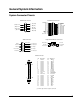
General System Information System Connector Pinouts Parallel Port Connector Serial Port Connector STROBE - 1 DO - 2 D1 - 3 D2 - 4 D3 - 5 D4 - 6 D5 - 7 D6 - 8 D7 - 9 ACK - 10 BUSY - 11 PE - 12 SLCT IN - 13 1 - CF (DCD) (DSR) CC - 6 2 - BB (RD) (RTS) CA - 7 3 - RA (TD) (CTS) CB - 8 4 - CD (DTR) (RI) CE - 9 5 - AB (CND) VGA Connector Keyboard and Mouse Connector 6 - Ground Red - 1 Green - 2 Blue - 3 Not Used - 4 Not Used - 6 +5V dc - 4 Not Used -2 11 - Not Used 7 - Ground 8 - Ground 14 - AUTO F
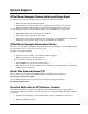
System Support HP NetServer Navigator Release History and Status Report To obtain a Release History or a Status Report, you will need a Document Number. • Release History: Document Number is 6005 • Status Report: The number is different for each Status Report. Each version of the HP NetServer Navigator CD-ROM has a four-digit Document Number printed on the disk. You can obtain the Release History and Status Report for your CD-ROM in one of these ways: • World Wide Web: netserver.hp.
• NetServer Support news articles • Frequently Asked Questions (FAQ) documents • Accessory information You can sign up for Proactive Notification by visiting the following World Wide Web URL: http://proact.hp.com:8088/NetServer netserver.hp.com/netserver/support Automated Fax In the U.S., call (800) 333-1917 from a push button tone phone to request that an index of available documents be sent to your fax machine. Call again to select the documents that you want transmitted. Outside the U.S.
• Other countries. • Call your local HP office. • Also available for part or manual identification: call (800) 227-8164 • After hours ordering: (916) 785-3035.
Troubleshooting Tools Common Installation Problems WARNING Before removing the cover, always disconnect the power cord and unplug telephone cables. Disconnect the power cord to avoid exposure to high energy levels that may cause burns when parts are short-circuited by metal objects such as tools or jewelry. Disconnect telephone cables to avoid exposure to shock hazard from telephone ringing voltages.
If the System Powers On but the System Fails the POST (Power-On Self Test) Do one of the following: • If the system gives a series of beeps, this indicates a system error. • If the system fails POST, an error message displays on the screen. If the System Passes the POST (Power-On Self Test) but Will Not Function If an error message displays on the screen, read the error message text for actions to take. If there is no error message, follow these steps: 1.
9
HP NetServer Utilities NOTE HP NetServer utilities are constantly changed and upgraded. See the specific HP Navigator CD-ROM for the latest information on utilities. Configuration Software There are many different configurations utilities available for NetServers. These include the EISA Configuration Utility, a Setup Utility in ROM, a SCSI Utility, and the Navigator CD-ROM. Which one the system uses depends on when the NetServer went into service. Below are highlights of the different utilities available.
Document Number nnnn Location of Document Number on Navigator CD Using the Navigator CD-ROM 1. Press the power-on button. 2. Press the CD-ROM drive eject button. 3. Place the HP NetServer Navigator CD-ROM in the drive, and press the eject button again to close the drive. 4. If the CD-ROM fails to autorun, follow the diagnostic instructions on the screen. 5. Go to the HP Navigator main menu. NOTE If this is the first time you are using Navigator, you are prompted to set the language, time, and date.
Configuration Assistant and Installation Assistant Configuration Assistant guides you through the steps necessary to configure the HP NetServer. You can view configuration advisories and change your hardware if necessary. Insert the HP NetServer Navigator CD-ROM into the CD-ROM drive. If the system fails to start, follow the instructions on the screen. 1. Set language, time, and date, if necessary. 2. Go to the HP NetServer Navigator main menu and select Configuration Assistant and Installation Assistant.
TopTools for Servers HP TopTools for Servers is new browser-based management software that provides remote administration and monitoring of critical HP NetServer components. TopTools provides vital information for the fastest troubleshooting and proactive management of NetServers. Processors, memory, storage, and NICs are a few examples of the components managed by TopTools.
Press F2 while the prompt is displayed. More boot messages appear, followed by the message Entering Setup... After the embedded (Symbios) SCSI Configuration initialization and the Optional ROM scan both finish, the menu bar of the Setup Utility appears. If you do not press F2, the HP NetServer boots normally. Using the Setup Screens Online help explains the settings displayed on the Setup Utility screens.
2. Press the Reset button on the front of the HP NetServer. The HP NetServer will boot from the HP NetServer Navigator CD-ROM. The HP NetServer Navigator Main Menu will appear. 3. To access the express or custom configuration, select "Configure NetServer" and press Enter to access Express or Custom configuration options. At the next menu, select "Express" or "Custom" and follow directions. Or go to NetServer Utilities and select EISA Configuration Utility.
Initiate Sync Negotiation Yes Maximum Sync Transfer Rate 10 MHz Enable Disconnection Yes Initiate Wide Negotiation (ID 0-7) No (ID 8-15) Yes Send Start Unit SCSI Command No Include In BIOS Scan Yes Running the SCSISelect Utility To start the SCSISelect utility: 1. Turn on or reboot your system. During system start-up or reset, a BIOS banner appears. The BIOS banner includes a description of each SCSI device connected to the host adapter and its corresponding SCSI ID number.
/H displays the System Administration Manager in 43-line mode if you have an EGA display. Displays the System Administration Manager in 50-line mode if you have a VGA display. /K prevents the computer from supporting the use of a mouse in the EISA Configuration Utility even if one is present. /M displays the System Administration Manager screens in black and white. /N modeling mode. Allows you to edit or create a custom SCI file that can be saved without changing the contents of CMOS.
Creating the Proper Operating Environment for the System Administration Manager To avoid potential problems, create the proper operating environment before using the System Administration Manager on a hard disk. 1. Modify the CONFIG.SYS file included with the System Administration Manager. This file originally contains the following lines: COUNTRY001,A:\COUNTRY.SYS DEVICE=A:\DISPLAY.SYS CON:(,437,2) DEVICE=HIMEM.SYS SHELL=A:\SAM.EXE /P Change to the following: COUNTRY001,C:\HPSYS\COUNTRY.
• To save the configuration values and reboot the system so that these values take effect, press Esc and then F4. • To exit from Setup without changes, press Esc and F6. Exiting Setup After you have made all desired changes to the Setup Utility pages, press Esc to display the Exiting Setup menu. Press F4 to save the changes and reboot the system. If you want to exit without saving the changes, press F6.
PrintCFG Syntax Variables that you fill in appear in italics. Optional parameters are enclosed in brackets [ ]. Do not enter the brackets. PRINTCFG [drive:]\HPSYS\filename.cfg [>PRN] Parameter Description drive: is the drive on which the CFG file is stored. The default is the active drive. HPSYS specifies the path from the root directory to the directory where the CFG file is stored. The default is the current directory. filename.cfg is the name of the CFG file. You must specify the CFG extension.
Use Page Up and Page Down to view the information you need. Running HPView from the System Administration Manager program: If SAM (System Administration Manager) is in the HPSYS directory on the hard disk drive, change to that directory, and type "SAM." Or insert #1 Diskette in drive A and then turn on the server. 1. Select "Run HPView Utility." 2. Use Page Up and Page Down to view the information you need. 3. Select to return to the previous screen.
w Perform an NVRAM update with minimal user interaction (whisper mode). Typically used in a manufacturing environment. Example: A:\hpupdate -1 -e -p Update the system language to French, do not change the versions of any components (system BIOS, Video BIOS, etc.) and clear the screen if the user aborts the language update process. HPUpdate Utility and HP NetServer LE, LF 1. Set the BIOS switch in the computer to UNLOCKed. 2. Insert the HPUpdate Utility diskette in drive A. 3.
F. Press ENTER to Continue with programming. 4. Remove the diskette and press ENTER to reboot the system. CAUTION Although the Flash Memory Utility includes safeguards to protect the NVRAM from damage, it is still possible to damage the server's NVRAM if there is a loss of power while the update is in progress. You will see a warning about this before the update process begins. If the update is in progress and there is a loss of power to the server, you must replace the system board.
• no access to operating system error logs, since the OS is not operating at the same time as the diagnostic tools • limited ability to test only a single component at a time • inability to indicate problems with wrongly configured systems or the network HP NetServer Diagnostic Assistant Before Diagtools, there was Diagnostic Assistant.
Accessing the Disk Array Utilities The Disk Array Utilities are used to perform disk array configuration tasks during initial HP NetServer installation and when changing disk array options. The Disk Array Utilities reside on the HP NetServer Manager CD-ROM and can be accessed in three ways: ◊ Express Configuration contains the Disk Array Utilities as one of the steps when a controller card is installed and should be used when initially setting up the HP NetServer.
Low-End Systems 27
HP NetServer E30 Covers WARNING Before removing the cover, always disconnect the power cord and unplug telephone cables. Disconnect the power cord to avoid exposure to high energy levels that may cause burns when parts are short-circuited by metal objects such as tools or jewelry. Disconnect telephone cables to avoid exposure to shock hazard from telephone ringing voltages.
HP NetServer E 30 Product Configurations Processor Upgrades Not applicable, none available Memory 16MB ECC standard (2x8MB 60ns SIMMs - fast page mode not EDO) - 6 total slots Expandable to 192MB (6x32MB) Cache Memory 256 KB second level write-back cache standard Video Up to 1024x768 256 colour non-interlaced; 1 MB standard video memory NIC DeskDirect PCI 10BaseT adapter J2973A (World wide except Europe) DeskDirect PCI 10BaseT/Thin LAN adapter J2970A (Europe only) Controller Single channel busmas
8 MB SIMM D4890A 16 MB SIMM D4891A 32 MB SIMM D4892A Video Memory The NetServer E Series has two sockets in which to install the two 512 KB memory chips required, both of which must be installed at the same time. These chips are 256 K x 16 bit, 50 ns, Dual-CAS, SOJ, EDO. Beveled end Boot Device Priority Use the following boot device priority for determining which device will be the boot device for the server. 1. IDE CD-ROM Drive 2. Flexible Disk Drive 3. IDE hard disk drive 4.
I/O Board This HP NetServer contains six ISA- and PCI-compatible slots which provide the capability of adding accessory boards, such as disk controller boards and network interface boards. NOTE A board can be identified as ISA or PCI by the bracket-offset angle and the unique slot connector.
System Board System Board Retaining Latch Battery VRM (166 MHz Processor) or Shunt (133 MHz Processor) DIP Switch Package Power Supply Connector Display Monitor Connector Keyboard Connector Mouse Connector Processor chip (133 or 166 MHz) Com 1 Serial Port Connector Cache memory Bank C Memory SIMM Connectors Com 2 Serial Port Connector Bank B Bank A Parallel Port Connector Power Switch and Activity LED Connector Power Supply Connector IDE 1 Connector IDE 2 Connector Flexible disk connector System Bo
Processor Switch Settings The following table shows the settings that you must changed when installing your 166 MHz Intel CPU.
20 21 22 19 18 23 17 24 Parts List Fig Description Replacement Exchange 1a SIMM, 8 MB D4890-63001 D4890-69001 1b SIMM, 16 MB, 60 ns D4891-63001 D4891-69001 1c SIMM, 32 MB, 60 ns D4892-63001 D4892-69001 2 Cache assembly, 256 KB 0960-0936 3a CPU Chip, P54/166 1821-2604 3b CPU Chip, P54/133 1821-2295 4 Voltage Regulator (P5/166) 5063-7940 5 Shorting block (P5/133) 5063-7939 6 Heatsink 1205-0832 7 System board D4874-63001 8 Battery 1420-0314 9 Fan 3160-1054 10 SCSI
Fig Description Replacement 16 Guide, system board 5042-0507 17 Mass Storage Trays, 3 ½ inch 5002-1946 18 CD-ROM Drive D2896-63401 19 Flexible disk drive D2035-63121 20 Air Flow Guide 5042-1484 21 Mass storage rear cover ** not orderable 22 2.
Power Cords Country HP Part Number Country HP Part Number Australia 8120-1369 UK 8120-1351 United States 8120-1751 Japan 8120-4753 Denmark 8120-2956 Switzerland 8120-2104 Europe 8120-1689 Cables Only the following HP cables are supported: Cable Part Number Cable, Flexible disk 5182-3509 Cable, SCSI 5182-9323 Cable, IDE/CD-ROM 5182-3508 Fan 5182-9379 Specifications Power Availability 160W continuous, 200W peak Switch selectable input range for 115 or 230V input Power Supply nom
HP NetServer E 40 System Views Power Switch Power and Disk Drive Activity Front Panel Key Locked position Unlocked position Shelf 1 (Flexible disk drive) Shelf 2 (CD-ROM Drive) Serial B Shelf 3 (mass storage tray) Serial A Shelf 4 (mass storage tray provided) Factory seals (located on bottom of chassis) Parallel Port Mouse Keyboard Network Front Shelf 5 (behind cover) Monitor Mass storage cover Shelf 6 (behind cover) Line voltage switch Power connector Technical Information Label Front View 3
Covers Key lock Cover Release Latches Rear of chassis Clips inside rear of cover Cover Air cooling duct Bottom of cover T-hook Bottom of chassis Release Latches 40
I/O Boards System Board slot Slot 1— 16-bit ISA (half-length) or 32-bit PCI Slot 2— 32-bit PCI Slot 3— 32-bit PCI Slot 4— 16-bit ISA (half-length) or 32-bit PCI Slot 5— 16-bit ISA Slot 6— 16-bit ISA These slots allow you to install accessory boards as follows: • Slot 1 (the innermost) can be used for a short 16-bit ISA board or a 32-bit PCI board. • Slots 2 and 3 can be used for 32-bit PCI boards. • Slot 4 can be used for a full-length 16-bit ISA board or a 32-bit PCI board.
• ID 4 • ID 5 • ID 6 Memory The processor board has 6 sockets which accept memory SIMMs. This NetServer comes preinstalled with two 8 MB or 16 MB SIMMs. When installing additional memory, note the following: • You must install SIMMs in pairs which are the same size and type. • Only these HP SIMMs are supported: SIMM Type HP Product Number 8 MB SIMM D4890A 16 MB SIMM D4891A 32 MB SIMM D4892A 64 MB SIMM D4290A Video DRAM Your NetServer is supplied with 1 MB of video memory as standard.
Notches Beveled end Video Resolutions The video resolutions available for your NetServer depend on the operating system you are using and the amount of video memory. The tables below show the available video resolutions. Video Resolutions with 1 MB Memory Installed Resolution Number of Colors Video Refresh Rate 640 x 480 16, 256, 32K, 64K, 16M 60, 72, 75, 85 Hz 800 x 600 16, 256, 32K 56, 60, 72, 75, 85 Hz 1024 x 768 16, 256 43i, 60, 70, 72, 75, 85 Hz 1280 x 1024 16 43i, 60, 71.
System Board System Board Retaining Latch DIP Switch Package Processor chip Battery Com 1 Serial Port Connector Power Switch and Activity LED Connector Com 2 Serial Port Connector Parallel Port Connector Mouse Connector Keyboard Connector Display Monitor Connector Power Supply Connector Bank A Memory SIMM Connectors IDE 1 Connector Bank B IDE 2 Connector Bank C Flexible disk connector System Board Switch Settings Switch position 1-5 44 Factory preset Definition: (See table below) Select proc
CAUTION Position 10 on the system board DIP switch package is to be changed only by a Hewlett-Packard-authorized service provider. Setting this switch incorrectly could result in damage to the processor chip, system board, or other components. Damage due to incorrect switch settings is not covered by the HP warranty. Processor Switch Settings The following table shows the settings for each of the Intel CPUs. To set the switches correctly, observe the markings on the replacement CPU chip.
20 24 22 19 18 17 46 21 23
26 25 27 28 29 Parts List Fig Description Replacement Exchange 1a SIMM, 8 MB D4890-63001 1b SIMM, 16 MB, 60 ns D4891-63001 1c SIMM, 32 MB, 60 ns D4892-63001 D4892-69001 1d SIMM, 64 MB, 60 ns D4290-63002 D4290-69002 3a CPU Chip, P6/180 1821-3450 3b CPU Chip, P6/200 1821-3449 6 Heatsink 1205-1170 7 System board D4937-63002 8 Battery 1420-0314 9 Fan 3160-1054 10 SCSI controller 5064-1912 11a LAN Adapter, 10BT2 (Europe) J2970-61001 J2970-69001 11b LAN Adapter, 10B
Fig Description Replacement Exchange 17 Mass Storage Trays, 3 ½ inch 5002-1946 18 CD-ROM Drive D4381-63001 19 Flexible disk drive D2035-60282 20 Air Cooling Duct 5042-1492 21 Mass storage rear cover ** not orderable 22 2.
Power Cords Country HP Part Number Country HP Part Number Australia 8120-1369 UK 8120-1351 United States 8120-1751 Japan 8120-4753 Denmark 8120-2956 Switzerland 8120-2104 Europe 8120-1689 Cables Only the following HP cables are supported: Cable Part Number Cable, Flexible disk 5182-3509 Cable, SCSI 5182-9323 Cable, IDE/CD-ROM 5182-3508 Fan 5182-9379 Specifications Operating Environment Non-operating altitude: 40,000 feet (12,200 meters) Operating altitude: 10,000 feet (3048 me
Electrical Specifications Input Voltage Power Consumption 100 to 127 Volts AC ~ 5.0 A at 50 - 60 Hertz or 307 watts maximum with 110 - 220 volt line voltage 200 to 240 Volts AC ~ 2.
HP NetServer E45/E50 System Views Power Switch Power and Disk Drive Activity LED Front Panel Key Lock Locked Position Unlocked Position Serial B Serial A Parallel Shelf 4 (mass storage tray provided) Mouse Factory Seal (located on bottom of chassis) Keyboard Network Connector Monitor Front View Rear Cooling Fan Line Voltage Switch Power Connector Technical Reference Card and Diagnostic Assistant Diskette (located in pouch) Rear View Optional Tape Backup Drive (Type A Chassis) (Type B Chassis)
Covers Key lock Cover Release Latches Hook Air cooling duct/cover Fan cable Power supply harness 52
Rear of chassis Clips inside rear of cover Cover Bottom of cover Bottom of chassis Release Latches Memory The processor board has 6 sockets which accept SIMMs. This NetServer comes preinstalled with two 16 MB SIMMs. • You must install SIMMs in pairs which are the same size and type.
Boot Device Priority Use the following boot device priority for determining which device will be the boot device for the server. The NetServer searches for a bootable device in this order: 1. IDE CD-ROM Drive 2. Flexible Disk Drive 3. IDE hard disk drive 4.
System Board Slot 1 (occupied) — 16-bit ISA (half-length) or 32-bit PCI Slot 2 (available) — 32-bit PCI Slot 3 (occupied) — 32-bit PCI Slot 4 (available) — 16-bit ISA or 32-bit PCI Slot 5 (available) Slot 6 (available) — — 16-bit ISA 16-bit ISA 55
Exploded Views 8 7 3 1 2 6 16 10 9 11 15 12 13 56
20 24 21 22 23 Type A Chassis 19 18 17 Type B Chassis 57
26 25 27 28 29 Parts List Fig Description Replacement Exchange 1a SIMM, 8 MB D4890-63001 1b SIMM, 16 MB, 60 ns D4891-63001 1c SIMM, 32 MB, 60 ns D4892-63001 D4892-69001 1d SIMM, 64 MB, 60 ns D4290-63002 D4290-69002 2 Voltage Regulator Module 0950-3310 3a Processor Module, PII/233, E 45 D4973-63002 D4973-69002 3b Processor Module, PII/266, E 45 D4975-63001 D4975-69001 3c Processor Module, PII/300, E 50 D6034-63003 3d Processor Module, PII/333, E 50 D6034-63002 6 Slot
Fig Description Replacement Exchange 9 Rear Cooling Fan 5064-1984 10 SCSI controller board, E 45 5064-1985 10 SCSI controller board, E 50 5064-4633 11 LAN Adapter, 10/100BT J3171-61021 12 Backplane 5064-1843 15 Status Panel/Switch Assembly 5064-0736 16 Guide, system board 5042-0507 17 Mass Storage Trays (for Type A Chassis) 5002-3876 18 CD-ROM Drive D4383-63001 19 Flexible disk drive D2035-60152 20 Cooling Duct/Cover 5064-1886 21 Rear Cooling Fan 5064-1984 22 4.
Italian #ABZ C3758-60217 Norway #ABN C3758-60209 Turkish #AB8 C3758-60234 Swiss #ABP C3758-60211 Taiwan #AB0 C3758-60223 Swedish #ABS C3758-60212 UK/Irish #ABU C3758-60213 Power Cords Country HP Part Number Australia 8120-1369 United States 8120-1751 Denmark 8120-2956 Europe 8120-1689 UK 8120-1351 Japan 8120-4753 Switzerland 8120-2104 Cables Cable Part Number Cable, Flexible disk 5182-3509 Cable, SCSI 5182-9323 Cable, IDE/CD-ROM 5182-3508 Fan 5182-9379 System Board Sy
System Switches Switch position 1-5 Factory preset Definition: (See table below) Select processor speed settings. The switch positions may need to be changed when upgrading the processor (see table below). 6 Open Resets the CMOS configuration to the default values. Set the switch to the closed position and restart the NetServer to reset the CMOS. Return the switch to the open position and restart the NetServer to return to normal operation. 7 Open Clears the password.
Acoustic emission: Sound level (LpA): < 45 dB(A) Input Voltage Power Consumption 100 to 127 Volts AC ~ 5.0 A at 50 - 60 Hertz or 307 watts maximum with 110 - 220 volt line voltage 200 to 240 Volts AC ~ 2.
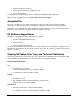
HP NetServer E60 System Views Power Floppy Drive CD-ROM Drive Optional Tape Backup Drive Keyboard Mouse Power On/ Off/Sleep On/Off/Sleep Indicator Key Lock Serial Port A Parallel Port Serial Port B SCSI/IDE Activity LAN RJ45 External SCSI Port Knock-out Video SVGA Fold Out Feet Covers To remove and replace the cover, you will need a Torx 15 driver or 1/4-inch flat blade screwdriver.
Front of Chassis Bottom of Chassis Installing the cover Memory The NetServer E 60's main memory is implemented with 3.3V, 100 MHz, unbuffered SDRAM DIMMs (Dual In-Line Memory Modules). The NetServer E 60 ships with at least 64 MB of main memory and supports up to 1 GB. Memory is available in the following DIMM capacities: 64, 128, and 256 MB. There are four DIMM sockets on the system board. DIMMs may be installed in any combination in any socket.
Exploded Views 1 2 3 6 5 4 7 65
9 8 7 10 11 12 20 19 18 16 15 14 66 17
6 21 13 Parts List NOTE The part numbers listed here are valid at the time of publication. Part numbers may change after publication. If a part number changes, HP's parts price list database will generally contain a reference to the new or revised part number. If a system board needs to be replaced, remove the processor, memory, video board, and any added accessory boards, and keep them with the system under repair.
9c Processor Module, PIII/500 D7154-63000 10a DIMM, E 60, 64 MB D7155-63000 D7155-69000 10b DIMM, E 60, 128 MB D7156-63000 D7156-69000 10c DIMM, E 60, 256 MB D7157-63000 D7157-69000 11 Battery, 3V coin D7140-63012 12 Air Flow Guide D7140-63011 13 Drive Cage Not orderable 14 Cable, flexible disk D7140-63006 15 Cable, IDE CD-ROM D7140-63005 16 Cable, SCSI, Internal D7140-63001 D7140-69001 17 Tape Drive, SureStore T20 SCSI Travan C4402 -63001 C4402-69001 18 Spacer Not or
United States 8120-1751 Japan 8120-4753 Denmark 8120-2956 Switzerland 8120-2104 Europe 8120-1689 System Board Power Memory Slots Terminator Processor Snap PS/2 Style Keyboard & Mouse Serial A Parallel Serial B Flexible Disk IDE1 IDE2 LAN (RJ45) AGP Video SCSI B PCI Slot 1 SCSI A PCI Slot 2 System Switches PCI Slot 3 Full-sized PCI Slot 4 Full-sized PCI Slot 5 Full-sized PCI Slot 6 shared with ISA Slot Full-sized Status Connector Snap System Board screw not visible when processor is ins
The switches and each of their definitions are listed below. Switch position 1 Factory preset OFF 2 Definition: Off - let's you power on your system by pressing any key on the keyboard or the power-on button. On – let's you power on the system only by pressing the power-on button. Unused 3 OFF Clears the password. Set the switch to the ON position and restart the NetServer to clear the password. Return the switch to the OFF position and restart the NetServer to return to normal operation.
Hardware Processors Intel Pentium II or III (up to 2 processors), supported speeds: 400, 450, and 500MHz. 512KB level 2 cache on processor. Chipset Intel 440BX AGPset with 66/100 MHz bus speed support. Memory Supports up to four SDRAM DIMMS for a maximum total of 1GB. Supported DIMM types: 64MB, 128MB, or 256MB unbuffered, 72 bits wide, ECC single-bit correcting, multi-bit detecting. Video AGP slot (rev. 1.0 compliant) with bundled ATI Rage IIc AGP (Accelerated Graphics Port) video with 4MB SDRAM.
System Accessories 73
HP NetServer Rack Storage/8 Rack Storage/8 Components The HP Rack Storage/8 System provides mass storage for use in an HP NetServer rack mount configuration. The HP Rack Storage/8 is compatible with the Small Computer System Interface (SCSI) industry standards Fast/Wide and Ultra/Wide are supported.
System Views Customer Serviceable Components Enclosure Environmental Service Monitoring Module Power Unit Fan Unit Fan Unit Power Unit Front Panel Keylock End Caps LEDs End Caps SCSI Drives Hot swap SCSI-2 hard disk drive modules can be installed in the HP Rack Storage/8. Drive Activity (LED) Light This LED glows green to indicate SCSI activity to and from the associated drive. In Place/Fault (LED) Light The LED lights above each drive indicate that drives status.
Rear View ESM Fan Unit Fan Unit Power Unit Power Unit Power Cord Connectors Power Cord Connectors Provides a connection for the AC power cord. Environmental Services Monitoring (ESM) Module This board provides three functions: Status reporting for the subsystem through the SCSI interface SCSI connection between the subsystem and the host Electrical isolation of internal and external buses. Power Supplies There are two hot-swap power supply units accessible from the rear of the system.
Exploded Views 1 2 3 4 5 6 7 7 6 8 77
Parts List NOTE The part numbers in the list were the ones that were available at the time of publication. Part numbers may change after publication. HP's parts price list database will generally contain a reference to the revised part number. * This part is not on an exploded view.
3. Place one of the Single Ended Terminators on the Bus 2 Output. Option Switches Set to Dual Bus Cabling When cabled as a dual bus storage unit, the HP Rack Storage/8 provides two independent SCSI buses. 1. Only option switch four is in the up position. 2. Place a Single Ended Terminator on the open Bus 1 Output connector and Bus 2 Output connector on the ESM Module.
SCSI Addresses Based on the selected cabling configuration (single or dual bus), the system automatically provides the SCSI addresses according to the following table: SCSI ID Reference Slot SCSI ID Dual Bus SCSI ID Single Bus 1 0 0 2 1 1 3 2 2 4 3 3 5 0 8 6 1 9 7 2 A 8 3 B Switch Settings Switch Number Position 0 Channel 0 SCSI Ids 1 2 3 4 OFF 0, 1,2,3 /E* ON 4, 5, 6, 7 /C* Channel 1 SCSI Ids OFF 0, 1, 2, 3 /E* ON 8, 9, A, B /F* Remote Start OFF <
HP Rack Storage/8 Rack Guidelines ALWAYS refer to the HP NetServer Rack Installation Road Map to be sure that you are proceeding correctly. Failure to perform this installation in accordance with the Road Map could result in significant extra installation effort. The HP Rack Storage/8 enclosure is supported in the rack by two support rails that are attached to the framework of the rack. Since the HP Rack Storage/8 enclosure weighs approximately 58.9 lb. (26.
Environmental Services Monitoring (ESM) Module WARNING The ESM is not hot-swappable. You must shut off the HP Rack Storage/8 AC supply before removing the ESM from the enclosure. Fault LED Locking and Release Mechanism Bus 2 Input Bus 1 Output Connecor Connecor Dial Locking and (Not Used) Release Mechanism Bus 1 Input Connecor Power LED Option Switch Bus 2 Output Connecor SCSI Connectors Bus 1 Provides two 68-pin, high-density SCSI interface connections for SCSI drive slots 1,2,3, and 4.
Non-operating Maximum 95% relative humidity Altitude Operating 3,046 m (10,000 ft) Non-operating 12,200 m (40,000 ft) Weight and Dimensions Height 13.3 cm (5.19 in) Width 48.2 cm (18.97 in) Depth 55.88 cm (22 in) Weight, fully loaded 36.6 kg (80.5 lb) Weight, without drives 26.8 kg (58.9 lb) Power Supply Specifications Power supply input voltage Redundant switching with the following power-factor auto-range AC input: 100 to 127 VAC ~ 6.0 A at 50/60 Hz 220 to 240 VAC ~ 3.
HP NetServer Rack Storage/12 Information System Views Drive Power Indicator Chassis Status LEDs Drive Activity Indicator Chassis Status LEDs The three Status LEDs indicate the current operating status of the HP Rack Storage/12. The following conditions are displayed by the Status LEDs: • Green: Normal operation. • Flashing Yellow: Warning condition exists in the chassis. Attention is required. Check the operating status of all components on the front and rear panels.
Low-Profile Drives 0 1 2 3 8 9101112131415 Half-Height Drives 0 1 3 8 10 11 13 14 Channel 1 Channel 2 Rear View Power Supplies Power Switch Management Board Ultra2 SCSI Host Connector 2 Ultra2 SCSI Host Connector 1 Power Switch The power switch controls AC power to the HP Rack Storage/12. The switch is located behind a hinged cover to prevent accidental power off. NOTE 5 VDC standby power is supplied to the HP Rack Storage/12 even when the power switch is set OFF.
• Off: No power supplied to the RS/12 SCSI card. 68-Pin Connector The 68-pin high-density connector connects the HP Rack Storage/12 to the host system. SCSI bus termination is inside the HP Rack Storage/12. The host system and the HP Rack Storage/12 can be connected by external SCSI cables up to 12 meters long. External SCSI cables are not included with the HP Rack Storage/12. Order SCSI cables from your HP Reseller.
Power Supplies AC Power Connector Power LED Fan Status LED Power Status LED The Power status LED displays the current operating condition of the power supply. • Green: Normal operation. • Off: No power or power supply failure. Fan Status LED The fan status LED displays the current operating condition of the fan module. • Green: Normal operation. • Off: No power or fan module failure.
RAID Management Refer to the HP NetRaid Series User Guide for information on HP NetRAID adapters, network operating system requirements, and use of the HP NetRAID configuration and management applications to configure the hard drives in the HP Rack Storage/12. HP Rack Storage/12 Configurations Simplex Configuration Simplex Cable Configuration Example Set Management Board Configuration Switch 1 Left for non-cluster configuration.
Set Management Board Configuration Switch 1 Left for non-cluster configuration.
Exploded Views 1 2 4 3 91
5 6 7 8 11 9 10 Parts List NOTE The part numbers in the list were the ones that were available at the time of publication. Part numbers may change after publication. * This part is not on an exploded view.
Fig Description Replacement * SCSI Slot Filler D5989-63004 * HP Rail Kit D5989-60003 Exchange Specifications Temperature Operating 5°to 35°C (40°to 95°F) Non-operating –40° to 65° C (-40°to -140°F) Humidity (noncondensing) Operating 20% to 80% relative humidity Non-operating Maximum 95% relative humidity Altitude Operating 3,046 m (10,000 ft) Non-operating 12,200 m (40,000 ft) Weight and Dimensions Height 13.2 cm (5.19 in) Width 46.36 cm (18.25 in) Depth 71.76 cm (28.
HP NetServer Rack Storage/12 FC Information System Views Front View Drive Power Indicator Chassis Status LEDs Drive Activity Indicator Front Panel Indicators Chassis Status LEDs Green: Normal operation. Flashing Yellow: Warning condition exists in the chassis. Attention is required. Check the operating status of components on the front and rear panels. Flashing Red: Fault condition exists in the chassis. Immediate attention is required.
SCSI Channels NOTE Each FCArray Controller card has 4 SCSI channels: • 2 internal SCSI buses (channels 0, 1) •2 external SCSI buses (channels 2, 3) SCSI Addresses The SCSI ID assigned to a hard drive is determined by its position in the drive cage. The SAF-TE chassis management processor is assigned SCSI ID 5. The default SCSI IDs are assigned to the 8 half–height drives and 12 low–profile drives.
Covers Thumbscrew Cover Tabs FCArray Controller Card 68-pin VHD Connectors Status LED 68-pin VHD Connectors Fibre Channel (HSSDC) Connectors FCArray Controller Card Ports and Indicator FCArray Controller Status LED Green: Normal operation Flashing Yellow: FCArray Controller card is temporally unavailable (rebooting), or a firmware revision mismatch exists between the two installed FCArray Controller cards. Flashing Red: Hardware fault on the FCArray Controller card or the card has gone offline.
DIMM Memory Card Phillips Screws (4) DIMM Memory Connector Battery Pack Connector Battery Pack FCArray Controller Card Battery Pack FCArray Controller Card Accessories Copper HSSDC GBIC Host Bus Adapter (HBA) Copper HSSDC Fibre Channel Cable & Connector Fiber Optic GBIC Optical Fibre Channel Cable & Connector Copper HSSDC Fibre Channel Cable & Connector Copper HSSDC GBIC Fiber Optic and Copper HSSDC GBICs and Cables 98
Management Board The Management board switches and indicators are shown below, but the switches are reserved for future use and not used. Temperature LED Configuration Switches 1 2 3 4 Switches are not Used Management Board Controls and Indicators Temperature LED The temperature LED displays the current environmental temperature status of the HP Rack System/12FC. Green: Normal operation. Flashing Yellow: High temperature warning within the chassis. Check fan operation, cooling, or airflow problems.
Power Status LED Green: Normal operation. Off: No power or power supply failure. Fan Status LED Green: Normal operation. Off: No power or fan module failure. RAID Management Refer to the FCArray Assistant Installation and User Guide for information on managing disk arrays used in or with the HP Rack Storage/12FC. Configurations Cluster Configurations Contact your Cluster Certified HP Reseller for assistance in installing your HP NetServer and HP Rack Storage/12FC in a cluster environment.
Single Host Configuration Host FC HBA with GBIC Fibre Channel Cable Rack Storage/12FC Blank Panel SCSI Cables Rack Storage/12 (Optional) Blank Panel 1 m SCSI Cable (only) FCArray Card Rack Storage/12 SCSI Card Terminator Rack Storage/8 (Optional) 101
Host Cluster Configuration Host Host (2) FC HBA with GBICs Copper Fibre Channel Cables Rack Storage/12FC Blank Panel SCSI Cables Rack Storage/12 (Optional) FCArray Card Rack Storage/12 SCSI Card Blank Panel 1 m SCSI Cable (only) Rack Storage/8 (Optional) 102 Terminator
Multi-Array Configuration Host FC HBA with GBIC Optical or Copper Fibre Channel Cables FC Hub with GBICs Copper Fibre Channel Cables Rack Storage/12FC Rack Storage/12FC Blank Panel SCSI Cables Rack Storage/12 (Optional) FCArray Card Rack Storage/12 SCSI Card Rack Storage/8 (Optional) Same Configuration as shown at Left (Limited to Available Hub Ports) Rack Storage/12 Blank Panel 1 m SCSI Cable (only) Terminator Rack Storage/8 103
Single Host and Hub Configuration Host FC HBA with GBIC 6 Port FC Hub with GBICs Rack Storage/12FC Optical or Copper Fibre Channel Cables Copper Fibre Channel Cables SCSI Cables(2) Rack Storage/12 (Optional) 1 m SCSI Cables (only) Rack Storage/8 (Optional) 104 Must Specify Cluster Mode Rack Storage/12 SCSI Cards (2)
Host Cluster and Hub Configuration Host (2) FC HBA with GBICs 6 Port FC Hub with GBICs Rack Storage/12FC Host Optical or Copper Fibre Channel Cables Copper Fibre Channel Cables SCSI Cables(2) 1 m SCSI Cables (only) Rack Storage/12 (Optional) Rack Storage/8 (Optional) Must Specify Cluster Mode Rack Storage/12 SCSI Cards (2) 105
Multi-Array and Hub Configuration Host (2) FC HBAs with GBICs 6 Port FC Hub with GBICs Optical or Copper Fibre Channel Cables Copper Fibre Channel Cables Rack Storage/12FC 6 Port FC Hub with GBICs Rack Storage/12FC SCSI Cables(2) 1 m SCSI Cables (only) Same Configuration as shown at Left Rack Storage/12 (Optional) Rack Storage/8 (Optional) 106 Rack Storage/12 Must Specify Cluster Mode Rack Storage/12 SCSI Cards (2) Rack Storage/8
Power Cabling 107
Exploded Views 1 2 4 3 108
5 6 7 12 8 9 11 10 Parts List NOTE The part numbers provided in the list are the most current part numbers available at the time of publication. Part numbers may change after the date of the publication. HP's parts price list database will generally contain a reference to the revised part number. * This part is not in an exploded view.
Descriptions Replacement Exchange * Fibre Channel HBA D6977-63001 D6977-69001 * Fibre Channel Hub D6976-63001 D6976-69001 * Fibre Channel Optical GBIC D6975-63001 * Fibre Channel Copper GBIC D6976-63002 * Cable, Optical, 100 meters D6981-63001 * Cable, Copper, 3 meters D6978-63001 * Cable, Copper, 5 meters D6979-63001 * Cable, Copper, 10 meters D7080-63001 * Cable, Copper, 30 meters D7081-63001 * Cable, Copper, 50 meters D6980-63001 * HP Rail Kit, Fibre Channel Hub D6976
Nominal Volts Amps Watts 100 5.48 537 120 4.51 530 200 2.61 512 230 2.
Notes 113
114
115
116
Index A Accessories RS/12FC, 98 accessory boards resource conflicts from, 16 Advanced Configuration Settings, 18 advanced dealer mode SAM, 17 altitude RS/8 operating, 83 automated FAX help system, 4 B BBS HP support bulletin board, 4 BIOS switch HPUpdate Utility, 23 BIOS update, 13 boot device priority remove built-in SCSI channels from boot order, 15 Boot Device Priority E30, 31 E40, 41 E45, 54 E50, 54 E60, 64 bus RS/8 dual, 79 buses RS/8 SCSI, 79 C cable RS/8 short bridge, 78 cables E30, 37 E40, 49 Cables
E40, 45 E45, 56 E50, 56 E60, 65 RS/12, 91 RS/12FC, 108 RS/8, 77 Express configuration, 13 Express Configuration, 13 external mass storage RS/8, 74 F fault LED RS/8, 75 FAX help systems, 4 FCArray Controller Card RS/12FC, 97 H help electronic newsletter, 4 FAX systems for, 4 HP PC support bulletin board, 4 HP Proactive Notification, 3 Internet sites, 3 Release History, 3 Status Report, 3 Support News, 4 hot swap hard disk drive removing internal drives from boot order, 15 hot-swap disk module keylock RS/8, 7
P part numbers E 40, 47 E 40 power cord, 49 E Series keyboards, 48 E30, 35 E30 keyboards, 36 E30 power cord, 37 Parts List E40, 47 E45, 58 E50, 58 E60, 67 RS/12, 92 RS/12FC, 109 RS/8, 78 PcANYWHERE32, 14 pinouts, 1 power availability E Series, 50 power consumption E Series, 37, 50 power cords E30, 37 E40, 49 Power Cords E45, 60 E50, 60 E60, 68 power LED, 82 Power Supplies RS/12FC, 99 power supply E 30, 37 RS/8, 76 RS/8 input, 83 RS/8 output, 83 RS/8 specifications, 81 PrintCFG utility, 20 Proactive Notifica
E60, 70 RS/12, 93 RS/12FC, 110 RS/8, 82 Status Report, 11 switch option, 82 switches RS/8 option, 78 System Board E30, 33 E40, 44 E45, 60 E50, 60 E60, 69 System Board Switch E30, 33 E40, 44 System Switch E60, 69 System Switches E45, 61 E50, 61 System Views E40, 39 E45, 51 E50, 51 E60, 63 RS/12, 85 RS/12FC, 95 RS/8, 75 T temperature RS/8 operating, 82 120 terminators RS/8, 79 TopTools for Servers, 14 TopTools Remote Control, 14 troubleshooting basics, 7 finding the problem, 7 U utilities BIOS Update, 14 Co