HP NetServer LC 2000/2000r Installation Guide HP Part Number D8514-90000 Printed November 1999
Notice The information contained in this document is subject to change without notice. Hewlett-Packard makes no warranty of any kind with regard to this material, including, but not limited to, the implied warranties of merchantability and fitness for a particular purpose. Hewlett-Packard shall not be liable for errors contained herein or for incidental or consequential damages in connection with the furnishing, performance, or use of this material.
Contents 1 Setting Up the HP NetServer ....................................................................... 1 Installation Guidelines.................................................................................... 1 Pedestal Installation ...................................................................................... 2 Rack Mount Installation ................................................................................. 5 2 Controls, Ports, and Indicators.....................................
Contents Hot Swap Configuration Options.............................................................. 38 Cabling Configurations ............................................................................ 43 Installing Hot Swap Hard Drives................................................................... 46 Removing Hot Swap Hard Drives................................................................. 50 Installing Non-Hot Swap Storage Devices....................................................
Contents Attaching the Front Bezel ........................................................................ 94 Continuing with the Rack Installation Process .............................................. 95 9 Connecting the Monitor, Keyboard, Mouse, and UPS ............................. 97 Introduction ................................................................................................. 97 Connecting the Monitor, Keyboard, and Mouse........................................
Contents Overview ....................................................................................................127 Using Information Assistant ........................................................................127 Getting Help ...........................................................................................127 Finding Information.................................................................................127 Copying and Printing Information ........................................
Contents Environmental Requirements......................................................................163 Physical Requirements ...............................................................................164 Video Support ........................................................................................165 B Regulatory Information ............................................................................167 Regulatory Notices - Electromagnetic Compliance ......................................
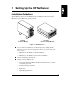
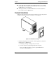
1 Setting Up the HP NetServer Installation Guidelines This Installation Guide is for the HP NetServer LC 2000 pedestal model, and the HP NetServer LC 2000r rack-optimized model. LC 2000r (Rack-mounted Model) LC 2000 (Pedestal Model) Figure 1-1. HP NetServers l For a trouble-free installation, read this chapter before taking the HP NetServer out of its box. This chapter lists what to do, and in what order.
Chapter 1 Setting Up the HP NetServer l Use the removable and reusable rack-mounting handles to move and place the LC 2000r in the rack. Remove the handles only when you have secured the HP NetServer to the rack slides. l The height at which you install the HP NetServer in the rack determines how you will service the HP NetServer. Pedestal Installation Follow the setup steps in the exact order shown below for a successful pedestal installation. Skip any steps that do not apply to your installation.
Chapter 1 Setting Up the HP NetServer CAUTION The HP NetServer LC 2000 weighs approximately 80 lbs. (36 kg), which may be more than one person should lift. Do not attempt to lift the HP NetServer by yourself. Failure to observe this warning could result in serious injury, or damage to the HP NetServer. 2. Familiarize yourself with the HP NetServer’s controls, ports, and indicators. Refer to Chapter 2, "Controls, Ports, and Indicators." 3.
Chapter 1 Setting Up the HP NetServer 11. Connect all other external cables to the rear of the HP NetServer. 12. Obtain the release history of the HP NetServer Navigator CD-ROM provided with the HP NetServer to ensure you have the latest Navigator CD-ROM. Refer to Chapter 10, "Configuring the HP NetServer." 13. Power up the HP NetServer. Refer to Chapter 2, "Controls, Ports, and Indicators." 14. Insert the Navigator CD-ROM and reboot the HP NetServer. 15.
Chapter 1 Setting Up the HP NetServer Rack Mount Installation Follow the setup steps in the exact order shown below for a successful rack installation. Skip any steps that do not apply to your installation. Shown Removed for Detail Figure 1-3. HP NetServer LC 2000r 1. Unpack the shipping box and verify the contents against the Contents List included with your HP NetServer. a. If anything is missing or damaged, call your reseller. b. Store the empty boxes and packing material in a safe place.
Chapter 1 Setting Up the HP NetServer 3. If you have optional items to add to the HP NetServer (memory, accessory boards, mass storage, or processors), remove the bezel and the top cover. ◊ If there are no optional items to install, skip to Step 12. ◊ Refer to Chapter 3, "Opening and Closing the HP NetServer." 4. If you have items such as a processor, DIMMs, and accessory boards to install, do so at this time.
Chapter 1 Setting Up the HP NetServer 13. Connect the monitor, keyboard, and mouse to the rear of the HP NetServer. Refer to Chapter 9, "Connecting Monitor, Keyboard, Mouse, and UPS." 14. Connect all other external cables to the rear of the HP NetServer. 15. Obtain the release history of the HP NetServer Navigator CD-ROM provided with the HP NetServer, to ensure you have the latest Navigator CD-ROM. Refer to Chapter 10, "Configuring the HP NetServer." 16. Power up the HP NetServer.
2 Controls, Ports, and Indicators Front of HP NetServer D is Fa k Te n m Po pe w ra R er tur es S e er up ve p d ly This chapter describes the controls, ports and indicators on the front and rear of the HP NetServer LC 2000 and LC 2000r. Figures 2-1 and 2-2 below show the HP NetServers LC 2000/LC 2000r as pedestal and rack models respectively. Power LED Keyboard Lock LED RESET RE S E T Power Button Reset Keyboard Lock Button Button Cover Removed for Clarity Figure 2-1.
Chapter 2 Controls, Ports, and Indicators Power, Reset, and Keyboard Lock Buttons The control buttons shown in Figures 2-1 and 2-2 are described in the Table 2-1. Table 2-1. Power, Reset, and Keyboard Lock Buttons and LEDs Control/LED Power On/Off/ Sleep Button Description This button turns the HP NetServer power On or Off, and if available, also transitions the NetServer between Power On and sleep states. If sleep states are not available, then this button only turns power On or Off.
Chapter 2 Controls, Ports and Indicators Front Panel LED Indicators Table 2-2. Component Indicators LED ICON Disk LED Description This Disk LED has two distinctive states: l l off for inactive operation blinking Green for SCSI drive activity. Temperature LED This Temperature LED has three distinctive colors: l steady Green for normal operation l blinking Red at 1 Hz blink rate for an overheated condition inside the HP NetServer l blinking Amber at 0.5 Hz blink rate for a warning condition.
Chapter 2 Controls, Ports, and Indicators Hot Swap Disk Drive Indicators Each of the Hot Swap hard disk drives has two LED indicators, one for operational status and one for activity status. Light pipes on each drive module transmit light to the front from the LEDs on the inside rear of the hot-swap mass storage cage. See Table 2-3 and Figure 2-3. Table 2-3.
Chapter 2 Controls, Ports and Indicators Non-Hot Swap Device Indicators The indicators for non-Hot Swap devices, which provide operational status, are also shown in Figure 2-3. The indicators shown in Figure 2-3 also apply to the rack-mount model (LC 2000r). See Table 2-4 for Backup Tape drive LED Codes. Table 2-4.
Chapter 2 Controls, Ports, and Indicators Rear Panel Indicators and Ports The HP NetServer’s rear panel includes communication ports, the AC power inlets, and the NetServer’s power supplies. Figure 2-4 shows the rear of the HP NetServer. Knockout for External SCSI Connector (Optional) Redundant Power Supply #2 (Optional) Communication Ports AC Power Inlets Power Supply #1 Figure 2-4.
Chapter 2 Controls, Ports and Indicators Power Supply Module Indicator Each HP NetServer power supply module has an indicator as shown in Figure 2-5, and each power supply has its own power cord connection. The HP NetServer comes with one power supply module standard, and a second power supply module for redundancy is optional. Release Latch Power Indicator Handle Strainrelief Figure 2-5. Power Supply LED NOTE The release latch, which is spring loaded, must be up to insert the power cord.
Chapter 2 Controls, Ports, and Indicators Communication Ports The connectors on the HP NetServer’s rear panel are shown in Figure 2-6 and described below. Keyboard Video Mouse NIC (Embedded) Serial Management Figure 2-6. Rear Panel Ports l Management – This connector supports the embedded Integrated Remote Assistant and links the HP NetServer to a console for real time monitoring and diagnosis of the NetServer's operation. l Serial A – This is the standard serial port connector.
Chapter 2 Controls, Ports and Indicators NIC Indicators The embedded NIC (Network Interface Card) has two LEDs associated with it, which can only be seen from the rear of the HP NetServer. See Figure 2-7 and Table 2-6. Link/Activity LED Transfer Rate LED Figure 2-7. NIC LEDs Table 2-6. NIC LED Code Indicator Link/Activity LED Definition This LED turns solid green to indicate that it is linked and properly connected.
Chapter 2 Controls, Ports, and Indicators Applying Power to the HP NetServer Powering Up the HP NetServer 1. Ensure the HP NetServer’s power cord or power cords are connected to the power source. See Figure 2-4. 2. Press the Power button on the front control panel. See Figure 2-1 or 2-2. NOTE Each time AC power is applied (power cord is plugged in), there is a 15 second delay (self test) before the front control panel will respond to your actions. Powering Down the HP NetServer 1.
Chapter 2 Controls, Ports and Indicators Sleep States (ACPI) The HP NetServer supports the ACPI (Advanced Configuration and Power Interface) standard, which is a key component of a NOS’s directed power management. The supported features are only available when an ACPI-compliant NOS is installed on the NetServer. The term “sleep state” refers to any of several reduced power consumption states in which normal NOS activity has ceased.
Chapter 2 20 Controls, Ports, and Indicators NOTE The HP NetServer power button will force a power down without waiting for the NOS to gracefully shut down the system if the power button is pressed and held in excess of four seconds. CAUTION If the power button override is used, there is a strong possibility of corrupted or lost data.
3 Opening and Closing the HP NetServer Introduction This chapter describes how to safely extend the rack-mounted HP NetServer LC 2000r out of the rack and how to remove and replace the covers from the HP NetServer LC 2000r and the pedestal model, HP NetServer LC 2000. This chapter also describes how to remove and replace the pedestal base from the HP NetServer LC 2000. WARNING Before removing the covers, shut down the operating system and disconnect the power cords and unplug telephone cables.
Chapter 3 Opening and Closing the HP NetServer Removing the HP NetServer’s Covers The HP NetServer’s covers are designated top and bottom for the rack-mounted version and left and right for the pedestal version. Removing Covers – Rack-Mount (LC 2000r) Use this procedure to remove the bezel and then safely extend the NetServer to where you can remove the covers (top and bottom) from the HP NetServer LC 2000r.
Chapter 3 Opening and Closing the HP NetServer 3. Press the power switch on the HP NetServer’s control panel when prompted by the operating system. Normally, this completes the power down procedure. 4. Disconnect the power cord or cords from the power source. NOTE The power supplies will continue to provide standby current to the NetServer until the power cable is disconnected. 5. At the front of the HP NetServer, extend the anti-tip foot from under the front of the rack.
Chapter 3 Opening and Closing the HP NetServer 6. Swing the bezel open to the left to access the Bezel Release Tab. 7. Press down on the blue Release Tab as shown in Figure 3-2 to release the bezel from the chassis. Slide Securing Screws (2) Press down on Blue Tab to Release Bezel Blue Slide Release Button (2) Hinge Pins (3) Figure 3-2. Removing the HP NetServer LC 2000r’s Bezel 8. Lift the bezel away from the front of the HP NetServer.
Chapter 3 Opening and Closing the HP NetServer 9. Unscrew the slide securing screw (2) on each bracket securing the chassis to the column adapter on each side of the rack. See Figure 3-3. 10. Press in on each blue Slide Release button (2) with both hands to slide the HP NetServer out of the rack. See Figure 3-3. Slide Securing Screws (2) Hinge Pins(3) Handles(2) Figure 3-3. Releasing the Securing Buttons 11.
Chapter 3 Opening and Closing the HP NetServer Figure 3-4. Extending the HP NetServer LC 2000r CAUTION To prevent damage to the covers, support the cover as you remove it from the HP NetServer. The NetServer’s covers are heavy. 12. To remove the top cover, use the key provided to unlock the Mass Storage Cage and release the top cover. 13. Loosen the thumbscrew on the front of the chassis for the top cover and then pull the cover forward to disengage. 14. Lift the top cover up and away from the chassis.
Chapter 3 Opening and Closing the HP NetServer Top Cover Cover Pull Bottom Cover Figure 3-5. Removing HP NetServer LC 2000r Covers 15. If necessary, remove the bottom cover by loosening the thumbscrew at the front of the HP NetServer with one hand. See Figure 3-5. The bottom cover does not provide any additional access to the interior, except the bottom of the mass storage drives and the control panel board. 16.
Chapter 3 Opening and Closing the HP NetServer 24. Slide the HP NetServer into the rack. 25. To replace the front bezel, reverse the procedure by positioning the bezel over the hinge pins at the front of the HP NetServer’s chassis. 26. Press the down on the Blue Bezel Release tab to engage the hinge pins of the bezel and then release it. 27. If the NetServer is not in a restricted-access area, tighten both slide securing screws. See Figures 3-2 and 3-3. 28. Return the HP NetServer to normal operation.
Chapter 3 Opening and Closing the HP NetServer 3. Press the power switch on the HP NetServer’s control panel when prompted by the operating system. Normally, this completes the power-down procedure. 4. Disconnect the power cord from its power source. 5. To remove the bezel, pull the top of the bezel forward until it unsnaps, then lift the entire bezel upward and away from the chassis. See Figure 3-6.
Chapter 3 Opening and Closing the HP NetServer 6. To remove the left side cover, use the key provided to unlock the Mass Storage Cage and release the left side cover. 7. Loosen the thumbscrew on the front of the chassis for the left side cover and then pull the cover forward to disengage it. 8. Move it to the left and away from the chassis. See Figure 3-7. 9. If necessary, remove the right side cover by loosening its thumbscrew on the front of the chassis.
Chapter 3 Opening and Closing the HP NetServer 12. To replace the left side cover, position the cover’s tabs next to the respective holes along the outer edge on the side of the chassis. 13. Slide the cover toward the rear. 14. Tighten the thumbscrew at the front of the cover. 15. To replace the right side cover, position the cover’s tabs next to the respective holes along the outer edge on each side of the chassis. 16. Slide the cover toward the rear. 17.
Chapter 3 Opening and Closing the HP NetServer Removing the Pedestal The pedestal version of the HP NetServer LC 2000 mounts to an anti-tip pedestal, which can be easily removed, if necessary. 1. Perform Steps 1-4 in the previous section, "Removing Covers – Pedestal (LC 2000)." NOTE The front bezel is shown removed, but the bezel may remain on the chassis while removing the pedestal. 2. Disconnect all cables connected to the rear of the NetServer that would limit its rotation before continuing. 3.
4 Installing Mass Storage Devices Introduction This chapter describes how to install the internal mass storage devices, including the internal SCSI Hot Swap hard disk drives and the optional Tape Backup (DAT) Drive. The requirements for external SCSI drives are provided in the respective topic later in this chapter.
Chapter 4 Installing Mass Storage Devices Drive Bay Shelves The non-hot swap drives include the IDE CD-ROM and the 3.5 inch flexible disk drives which are standard for all HP NetServer models (LC 2000/2000r) and ship with each unit. The two empty drive shelves beneath the CD ROM drive support other non-hot swap SCSI devices, such as hard drives (3.5-inch or 5.25-inch), tape back-up devices, or other HP-tested (LVD or SE) SCSI accessories.
Chapter 4 Installing Mass Storage Devices You can change this boot order using the Setup Utility (BIOS) and the SCSI Configuration Utility during the boot process. Refer to Chapter 10 "Configuring the HP NetServer" for more information. By default the NetServer searches for boot devices in this order: 1. IDE CD-ROM drive 2. Flexible disk drive 3. SCSI A bus (typically Hot Swap Mass Storage Cage) 4. SCSI B bus (typically non-Hot Swap internal SCSI devices) 5. PCI Slot P1 6. PCI Slot P2 7. PCI slot P3 8.
Chapter 4 Installing Mass Storage Devices Mass Storage Guidelines • General Guidelines ◊ Use care when unpacking and handling the disk drives. The hard disk drives are very susceptible to mechanical shock and can be easily damaged by a drop as short as one-quarter of an inch. If the drop would crack an egg, it will damage the drive. ◊ Do not stack drives. ◊ Do not use high voltage differential (HVD) SCSI devices on any of the SCSI channels or damage will occur.
Chapter 4 Installing Mass Storage Devices • SCSI Drive Addressing ◊ The drives in the Hot Swap Cage are automatically assigned SCSI addresses by the HP NetServer. The Hot Swap drive’s address is dependent on its position within the drive cage and the combination of half-height and low-profile SCSI drives installed. Refer to Figures 4-2 through 4-5 for the automatic SCSI ID assignments. The Hot Swap Cage also supports the installation of a Duplex board, which divides the cage in two equal halves.
Chapter 4 Installing Mass Storage Devices If there are gaps in the cage, the drives may not receive the proper ventilation and could suffer thermal damage. • Filler Panels and Spacers ◊ Ensure all empty slots in the Hot Swap drive cage have filler panels inserted to ensure proper airflow. If there are fewer drives than the Hot Swap drive cage supports, a 1-inch filler panel must be inserted in each empty disk location. The filler panels ensure the drive cage has the proper ventilation and airflow.
Chapter 4 Installing Mass Storage Devices Rack-Mounted Configurations for SCSI Hot Swap Mass Storage Cage Single Bus Control - SCSI Connector A Filler Panels 1 1 0 A 2 2 1 A 3 3 2 A 4 4 3 A 5 5 8 A 6 6 9 A Slot Number Disk Drive SCSI Device ID SCSI Connector 1 1 0 A 2 3 4 2 2 A 5 6 3 8 A Slot Number Disk Drive SCSI Device ID SCSI Connector 1 1 0 A 2 3 2 2 A 4 3 3 A 5 4 8 A 6 5 9 A Slot Number Disk Drive SCSI Device ID SCSI Connector 1 1 0 A 2 3 2 2 A 4 5 3 8 A 6 4 9 A Slot Number
Chapter 4 Installing Mass Storage Devices Filler Panel Sl o Di t N s u SC k D m b SCSI riv er D SI eve Co i c nn e ID ec to r Sl o Di t N s u SC k D m b SCSI riv er SI Deve C ic on e ne ID ct or Pedestal Configurations for SCSI Hot Swap Mass Storage Cage Single Bus Control - Connector A 6 6 9 A 6 5 5 8 A 5 3 8 A 4 4 3 A 4 3 3 2 A 3 2 2 A 2 2 1 A 2 1 1 0 A 1 1 0 A 6 5 9 A 6 5 9 A 5 4 8 A 5 4 8 A 4 3 3 A 4 3 2 2 A 3 3 2 A 2 2 2 1 A 1 1 0 A 1 1 0 A 6 4 9 A 6 4 9 A 5 5 3 8 A 4
Chapter 4 Installing Mass Storage Devices Rack-Mounted Configurations for SCSI Hot Swap Mass Storage Cage Duplex Board Installed - Two Bus Control Connector A and B Filler Panel 1 1 0 B 2 3 2 3 1 2 B B Con B 4 4 0 A 5 6 5 6 1 2 A A Con A Slot Number Disk Drives SCSI Device ID SCSI Connector Center Line 1 2 1 0 B Con B 3 2 2 B 4 5 6 3 4 0 2 A A Con A Slot Number Disk Drives SCSI Device ID SCSI Connector Center Line Note: Con = Connector 1 2 3 1 2 0 2 B B Con B 4 5 3 4 0 1 A A Con A 6 5 2 A
Chapter 4 Installing Mass Storage Devices Sl o D tN is u SC k D m b SCSI riv er D SI eve C ic on e ne ID ct or Pedestal Configurations for SCSI Hot Swap Mass Storage Cage Duplex Board Installed - Two Bus Control Connectors A and B 6 6 2 A 5 5 1 A 4 4 0 A Con A Center Line 3 3 2 B 2 2 1 B Con B 1 1 0 B 6 5 2 A 5 4 1 A Con A 4 3 0 A 3 2 2 B 2 Center Line Con B 1 1 0 B 6 4 2 A 5 4 3 0 A 3 2 2 B 2 Con A Center Line Con B 1 1 0 B Con = Connector Figure 4-5.
Chapter 4 Installing Mass Storage Devices Cabling Configurations There are various SCSI cable configurations associated with the HP NetServer and if all possible SCSI devices and connections are used, then an additional SCSI disk controller is required. Table 4-1 describes the various cables and where each one can be connected. The example configurations shown in Figures 4-6 and 4-7 assume the maximum number of SCSI devices and connections.
Chapter 4 Installing Mass Storage Devices SCSI Cable Configurations Hot-Swap and Non-Hot Swap Drives (Single Bus Control - No Duplex Board Installed) SCSI Channel A SCSI Channel B Cable 1 Cable 2 Cable 3 Cable 4 CD-ROM External SCSI Connections (Optional) Non-Hot Swap SCSI Devices (Hard Drive and Back-up Tape Drive) Termination Flexible Disk Drive Connector A: Used for Top Half (Right Side) of Cage Daisy Chain from Top Half (Connector A) to Connector B Connector B: Used for Bottom Half (Left Side) o
Chapter 4 Installing Mass Storage Devices SCSI Cable Configurations Hot-Swap and Non-Hot Swap Drives (Two Bus Control - Duplex Board Installed) SCSI Channel A SCSI Channel B Cable 1 Cable 2 (2) Cable 3 Cable 4 CD-ROM External SCSI Connections (Optional) Non-Hot Swap SCSI Devices (Hard Drive and Back-up Tape Drive) Termination Flexible Disk Drive Connector A: Used for Top Half (Right Side) of Cage Connector B: Used for Bottom Half (Left Side) of Cage PCI SCSI Disk Controller Board System Board Hot-S
Chapter 4 Installing Mass Storage Devices Installing Hot Swap Hard Drives Use this section to install Hot Swap hard drives in the Hot Swap drive cage. CAUTION Protect the drive from static electricity by leaving it in its anti-static bag until you are ready to install it. Before handling the drive, touch any unpainted metal surface to discharge static electricity. When you remove the drive from the anti-static bag, handle it only by the frame. Do not touch the electrical components.
Chapter 4 Installing Mass Storage Devices 3. Remove any drive spacers, if necessary: a. Slide the drive spacer back, a fraction of an inch away from your body as you face the front of the drive. Drive spacers attach to the disk drive module with four small feet. b. Tilt up the front of the drive spacer to disengage the front two feet. c. Pull the drive spacer forward slightly to disengage the back two feet and lift. See Figure 4-9. Drive Spacer Figure 4-9.
Chapter 4 Installing Mass Storage Devices CAUTION To prevent snapping off the handle do not use extreme force when opening it. Open the handle until you feel resistance. 4. Open the drive module by pressing in on the locking latch at the end of the drive ejector handle and pulling the handle open. Locking tab pivots when the ejector handle is open Light Pipes (fragile) Drive ejector handle Locking Latch Figure 4-10.
Chapter 4 Installing Mass Storage Devices CAUTION Use caution when handling the drive to prevent damage to the fragile light pipes as you insert the drive. 5. Gently slide the drive module into the cage and stop when you feel resistance. See Figure 4-11. Figure 4-11. Inserting the Drive 6. Verify the pin behind the pivot end of the handle engages the hole in the edge of the cage. 7. Press the ejector handle in until you feel the latch click into place.
Chapter 4 Installing Mass Storage Devices Removing Hot Swap Hard Drives CAUTION You must remove the drive slowly to ensure the drive heads are parked prior to removal. Ensure you follow these instructions carefully to prevent handling damage, such as head slaps or head actuator unlocking. 1. To unlock the drive, push the locking latch in and then pull the ejector handle toward you. See Figures 4-10 and 4-12. 2. Gently pull the drive out about an inch to disengage the power connection. 3.
Chapter 4 Installing Mass Storage Devices Installing Non-Hot Swap Storage Devices Use this section to install any of the non-hot swap mass storage devices used as a hard drive or a tape backup storage. CAUTION Protect the drive from static electricity by leaving it in its anti-static bag until you are ready to install it. Before handling the drive, touch any unpainted metal surface to discharge static electricity. When you remove the drive from the anti-static bag, handle it only by the frame.
Chapter 4 Installing Mass Storage Devices 3. If working on a pedestal-mounted NetServer, remove the bezel and gain access to the HP NetServer’s non-hot swap-drive bays. Refer to Chapter 3, "Opening and Closing the HP NetServer." 4. If working on a rack-mounted NetServer, follow the appropriate instructions to safely extend the NetServer from the rack. Refer to Chapter 3, "Opening and Closing the HP NetServer." 5. Select an available drive bay for the device and remove the filler panel. 6.
Chapter 4 Installing Mass Storage Devices Connecting External SCSI Devices The HP NetServer may provide an external SCSI connector (optional) at the rear panel knockout as shown in Figure 4-14. The external SCSI connector is typically connected to a PCI SCSI disk controller board inserted in one of the PCI slots. An external SCSI connection may also be provided by a SCSI disk controller board or a DAC board inserted into one of the PCI slots as shown in Figure 4-14.
5 Installing Additional Memory Introduction This chapter provides the instructions for installing and removing DIMMs on the system board in the HP NetServer LC 2000 or LC 2000r. The video memory comes with 2MB standard and cannot be upgraded. NOTE The EDO DIMMs and PC 100 SDRAM DIMMs from earlier HP NetServer models will fit into the DIMM slots in the NetServer LC 2000/LC 2000r, but the EDO DIMMs and PC 100 SDRAM will not function properly. Use only 133 MHz SDRAM DIMMs acquired from HP.
Chapter 5 Installing Additional Memory Memory Installation Guidelines • The HP NetServer LC 2000/2000r uses only 133 MHz (PC133) SDRAM DIMMs, which are electrically different from the EDO and PC100 SDRAM memory modules used in previous HP NetServer models. • DIMM sizes supported are 64 MB, 128 MB, 256 MB, 512 MB, or 1 GB in any combination. • Supported memory capacity ranges from 64 MB to 4 GB maximum (1 GB per DIMM slot and 4 DIMM slots total). The minimum capacity is 64 MB (one DIMM).
Chapter 5 Installing Additional Memory To install additional memory in the HP NetServer, refer to the following procedure. 1. To gain access to the HP NetServer, perform one of the procedures listed below. NOTE It is not necessary to remove the system board from the HP NetServer to install the additional DIMM memory.
Chapter 5 Installing Additional Memory 5. Insert the DIMM fully into the slot, handling the DIMM by its edges. See Figures 5-2 and 5-3. The retaining clips should grasp the DIMM automatically if it is inserted properly. If the clips do not close, the DIMM is not inserted correctly. CAUTION Do not rock the DIMM into place, but apply firm and even pressure. If the retaining clips do not close, remove the DIMM and repeat Steps 2-5. Figure 5-3.
Chapter 5 Installing Additional Memory 7. If the NetServer is in a rack installation, return the chassis into the rack. Refer to Chapter 3, "Opening and Closing the HP NetServer." 8. Re-install the bezel onto the front of the HP NetServer. Refer to Chapter 3, "Opening and Closing the HP NetServer." 9. Reconnect the power cord(s). 10. Power on the HP NetServer according to the respective NOS power-up instructions. Refer to Chapter 2, "Controls, Ports, and Indicators." 11.
Chapter 5 Installing Additional Memory Figure 5-4. Removing a DIMM Module 6. Repeat Steps 2 through 5 to remove any additional desired DIMMs on the system board. NOTE Ensure the retaining clips on the DIMM slots for each DIMM are closed before replacing the cover onto the HP NetServer. An error will be displayed if all DIMMs are removed. 7. If all desired DIMMs have been removed, replace the cover. Refer to Chapter 3, "Opening and Closing the HP NetServer." 8.
6 Installing Additional Boards Introduction This chapter describes how to install accessory boards into the system board of the HP NetServer LC 2000/2000r. The system board provides up to six PCI slots (P1 through P6), two of which are 64-bit slots.
Chapter 6 Installing Additional Boards Boot Priority This section details the HP NetServer’s boot order by highest to lowest priority. The NetServer’s boot order (BIOS search order for a boot drive) should be considered when selecting a slot on the system board. This is especially important if you are installing a SCSI disk controller board. The disk controller’s boot priority is set by the board’s slot location. See Figure 6-1. The on-board SCSI consists of two channels, A and B.
Chapter 6 Installing Additional Boards IRQ Settings The IRQ settings are automatically assigned and don’t require user intervention. PCI boards have the capability of sharing hardware interrupts (IRQs) with other PCI boards, as stated in the PCI specifications, but this does not always prove to be true between board manufacturers. To solve this problem requires an in-depth knowledge of a server’s implementation to place a PCI board in a slot that would not conflict with another PCI board’s IRQ setting.
Chapter 6 Installing Additional Boards • Two PCI slots (P5-P6) support full-length 32- or 64-bit boards at clock rates of 33 MHz. These slots only support +5 VDC power and Universal boards. These slots have keys in the upper half of the board slot to prevent 3.3 volt boards from being inserted into the slots. CAUTION Some accessory board outputs may exceed U.S.
Chapter 6 Installing Additional Boards Open = Off Closed = On Shaded rectangle represents the position of slide switch. 2 Processor Speed (Bit 1) 3 Processor Speed (Bit 2) 4 Processor Speed (Bit 3) 5 Clear Configuration 6 Clear Password 8 FSB Speed (133/100 MHz) Rear of HP NetServer Figure 6-2. Configuration Switch Block Installing Accessory Boards Use this procedure to install all accessory boards. 1.
Chapter 6 Installing Additional Boards 5. Gain access to the NetServer by performing the appropriate procedure for the NetServer LC 2000 or the LC 2000r. ◊ If the NetServer is mounted on the pedestal, perform Steps 1-8 in the "Removing Covers – Pedestal (LC 2000)" in Chapter 3, "Opening and Closing the HP NetServer," to gain access to the NetServer.
Chapter 6 Installing Additional Boards 8. Remove the slot cover from the NetServer’s rear panel, before installing the new board into the slot, as shown in Figure 6-3. 2. Lift Latch 3. Remove Slot Cover 1. Open Tab Figure 6-3. Removing the Slot Cover NOTE Each PCI slot must have a slot cover or PCI board in the slot. Ensure all unused slots have slot covers in place. CAUTION Do not bend the PCI board to install it into the slot.
Chapter 6 Installing Additional Boards 9. Before installing the new PCI board: ◊ Verify there is no handle attached to it, especially if it is a full-length board. ◊ If it has a handle attached, remove the handle before installing the board into the slot. NOTE Use only the right side of the two slots in the board guide, when installing PCI boards into some of the PCI slots (P3 through P6) on the system board. 10. Align the board with its slot along its full length and position it into the slot. 11.
Chapter 6 Installing Additional Boards 1. Insert Board 2. Close Latch 3. Turn Tab Figure 6-4. Installing the Accessory Board 12. Secure the PCI board as shown in Figure 6-4. 13. If the installed accessory board requires an external connection or a connection to the System board, ensure the cable is properly attached. Refer to the accessory board documentation for connection requirements. 14. If accessory board installation is complete, re-install the cover on the NetServer.
Chapter 6 Installing Additional Boards 16. If all installation work is complete, return power to the NetServer according to the respective NOS power up instructions. 17. Use the respective NOS software to ensure the correct software drivers for the PCI board are loaded and verify correct operation.
7 Installing Additional Processors Introduction The HP NetServer LC 2000/2000r supports two processors in primary and secondary slots and both processors must operate at the same speed and cache size. The HP NetServer supports the Pentium III processors at a front side bus (FSB) speed of 133 MHz. Advanced processors will be supported as each one becomes available. Contact HP or your reseller for details.
Chapter 7 Installing Additional Processors CAUTION Do not set the processor speed switches to any other speed, as this can result in unreliable or intermittent performance, and data integrity may also be at risk. l Use only processor upgrade kits with the same HP product number. This ensures the processor type, clock speed, and cache size match, and that product numbers are compatible.
Chapter 7 Installing Additional Processors Installing the Processor The installation procedure is the same for the rack-mounted models as for the pedestal models of the NetServer once you gain access to the system board. CAUTION Use an anti-static wrist strap and a grounding mat. Wear a wrist-strap and use a static-dissipating work surface connected to the chassis when handling components. Ensure the metal of the wrist strap contacts your skin. 1.
Chapter 7 Installing Additional Processors 6. Verify the processor speed and FSB setting, before installing the second processor module. See Figures 7-1 and 7-2, and Tables 7-1 and 7-2. Both processor modules must have the same clock speed, cache size, FSB speed, and product number. 7. If installing two new processor modules, set the switches accordingly. Use a small, flat-blade screwdriver or similar tool. Open = Off Closed = On Shaded rectangle represents the position of slide switch.
Chapter 7 Installing Additional Processors NOTE Some processor speeds listed in Table 7-1 may not be supported. For the latest support information, visit the HP web site: http://www.hp.com/go/netserver NOTE The System board is shown removed from the HP NetServer for simplicity in the following figures, but it is not necessary to remove the system board to install the new processor module or the VRM. 8. Loosen the thumbscrew on the processor cage cover, and lift off the cover as shown in Figure 7-3.
Chapter 7 Installing Additional Processors 9. Remove the termination from the secondary processor slot by pressing in on the tabs and pulling directly upwards. See Figure 7-4. Terminator Figure 7-4.
Chapter 7 Installing Additional Processors 10. Remove the processor module from the sealed bag. 11. Open the latches on top of the processor slot. See Figure 7-5. If a processor is installed in the slot, the processor module will move up in the slot where you can grasp it for removal. Figure 7-5. Installing the Processor 12. Align the additional processor module over the secondary processor module slot. See Figure 7-5. 13. Gently push down on the processor module until it seats. 14.
Chapter 7 Installing Additional Processors 2nd VRM VRM Latches Figure 7-6. Installing VRM CAUTION To prevent damage to the VRM, do not push on the large flat surface or touch the components on the board as you push the VRM card down into the slot. Push only on the edges of the VRM board. 15. Open the VRM retaining latches as shown in Figure 7-6. 16. Align the VRM’s connector edge with the secondary VRM slot. See Figure 7-6.
8 Rack Mounting the HP NetServer Introduction This chapter tells how to mount the HP NetServer in an HP System/E or System/U rack. The illustration below shows the characteristics of the System/E and System/U racks. If you have the older HP Systems rack, see Chapter 13, "Alternative Rack Mounting," for instructions. (If you are mounting the NetServer in a non-HP rack, refer to the separate rack-mounting guide for third-party racks. It is packed in the accessories tray in the HP NetServer’s shipping box.
Chapter 8 NOTE Rack-Mounting the HP NetServer If you want to put your NetServer into a third-party rack not mentioned in the guide, you may be able to find relevant documentation on HP’s web site at the following URL: http://www.hp.com/netserver/support The HP NetServer rack mount kit requires five EIA units of space in the rack. Before mounting the NetServer, plan the NetServer’s location in the rack relative to other rack components. Proper placement is vital both for safety and operating efficiency.
Chapter 8 Rack-Mounting the HP NetServer Safety Precautions Always keep the following safety and environmental issues in mind, especially if you install the HP NetServer in a non-HP rack environment: l Optimum Operating Environment – The optimum operating conditions for the HP NetServer is in an environmental controlled computer room with a temperature range of 20 to 22°C (68 to 72°F) at 40 to 60% relative humidity.
Chapter 8 Rack-Mounting the HP NetServer Preparing the Rack The column adapters and rack nuts must be connected to the rack before mounting the slide mechanism. Once the slides are correctly mounted, then the HP NetServer LC 2000r can be installing into the rack. A cardboard rack mounting template comes with the HP NetServer. The template identifies the column adapter and rack nut locations on the rack.
Chapter 8 Rack-Mounting the HP NetServer 1. Find the rack-mounting template. If your HP NetServer is still in its box, the template should be in the accessories tray that sits on top of the NetServer itself. 2. Hold the template alongside the outside face (front) of the left front rack columns. 3. Line up the bottom of the template with the lower line of the NetServer’s location in the rack. The template covers a span of 5 EIA units, which is the height requirement of the HP NetServer. 4.
Chapter 8 Rack-Mounting the HP NetServer "#" represents the EIA unit numbers on the rack columns. # 14th Hole From Bottom # # Front of Rack Right Left # # 2nd Hole From Bottom # Bottom of HP NetServer Mark this face of the left-front and right-front columns. Figure 8-3. Location Marks on the Rack’s Front Columns 5. Turn the template over and use it to mount rack nuts (at 7th and 9th holes) on the left-rear and right-rear rack columns. The template provides you with the nut placement locations.
Chapter 8 Rack-Mounting the HP NetServer Attaching the Column Adapters and Slides 1. Pull the anti-tip foot forward out of the bottom of the rack. See Figure 8-6 for the anti-tip foot location. 2. Align the left HP column adapter to the left front column as shown in Figure 8-5. 3. Match the column adapter holes (2nd & 14th) to the marks on the front column and place the column adapter mounting holes behind the column face. See Figure 8-5. 4.
Chapter 8 Rack-Mounting the HP NetServer b. The two holes in the mounting flange should line up with the captive nuts (at 7th and 9th holes) in the column adapter and the two rack nuts you installed on each rear column. c. The extending portion of the slide (slide member) should point forward out of the rack. Mount Slides inside Column Adapters Extend rack’s anti-tip foot from front of rack for safety. Figure 8-6. Securing the Slides to the Rack Columns 7.
Chapter 8 Rack-Mounting the HP NetServer 8. Fasten the slide’s rear bracket to the rack nuts on the left-rear column. a. Secure the screws only loosely at first, so the bracket can settle into the lowest possible position. There is a dimple in the bracket to position the slides in the proper location. b. Then tighten the screws until the bracket is held firmly to the column. 9. Attach the other slide to the right-front column adapter and right-rear rack column by repeating Steps 6-8.
Chapter 8 Rack-Mounting the HP NetServer Mounting Tabs Leveler Screws (4) Slide Members Anti-tip Foot Figure 8-7. Pulling Out the Slides 3. Pull out both slides until the slide members are fully extended. See Figure 8-7. The slides click into position when locked. This locked position prevents the slides from moving back into the rack, unless the release latches are pressed as shown in Figure 8-10. 4.
Chapter 8 Rack-Mounting the HP NetServer Channel(2) Figure 8-8. Mounting the HP NetServer on the Slides 7. Move the slide members into the NetServer’s channels until both slide members are underneath all four of the NetServer's handles. See Figures 8-8 and 8-9. The mounting tabs in the slides should be in position to fit into the openings in the chassis. See Figures 8-7 and 8-8. 8. Lower the NetServer onto the slide members. See Figure 8-9.
Chapter 8 Rack-Mounting the HP NetServer Figure 8-9. Removing the Mounting Handles 10. Insert the flathead screws into the slides’ holes at the rear and the panheads screws in the other four places to secure the chassis to the slides. 11. Use a T-15 Torx driver to remove the screws holding the handles to the NetServer. See Figure 8-9. 12. Take the handles off the NetServer and store the handles and screws in a convenient place. See Figure 8-9.
Chapter 8 Rack-Mounting the HP NetServer Figure 8-10. Pressing in the Release Latches 14. Verify the NetServer will slide all the way into the rack, before continuing with the procedures. 15. Continue with the next section, "Attaching the Cable Management Arm," before securing the HP NetServer in the rack. Attaching the Cable Management Arm Use this procedure to mount the Cable Management Arm on the HP NetServer LC 2000r when mounted in the HP System/E or System /U racks.
Chapter 8 Rack-Mounting the HP NetServer WARNING Before sliding out the HP NetServer LC 2000r, ensure the anti-tip foot is still extended from the front of the rack. A tip-over hazard exists, so never slide more than one component out of the rack at a time. 1. Ensure the HP NetServer LC 2000r is pushed all the way into the rack. 2. At the rear of the HP NetServer, place rack nuts on the left column in the 12th and 14th holes above the baseline (bottom) of the NetServer. See Figure 8-11.
Chapter 8 Rack-Mounting the HP NetServer Rear of HP NetServer Left Rear Rack Column Cable Management Arm Figure 8-12. Attaching the Cable Management Arm 5. Attach the other flange of the cable arm to the rear column of the rack with the two M-5 pan head T-25 Torx screws, which are included with the Arm. 6. Attach the flange to the NetServer with the two 8-32 pan head Torx T-20 screws, which are included with the Arm. See Figure 8-12. 7.
Chapter 8 Rack-Mounting the HP NetServer Attaching the Front Bezel The front bezel attaches to the HP NetServer by a hinge on the left and a latch on the right. The hinge has three spring-loaded hinge pins to secure the bezel. The bezel is held in place on the right with a latch allowing the bezel to swing open when pulled from the right. The chassis is shipped with the bezel hinge and latch in place.
Chapter 8 Rack-Mounting the HP NetServer 2. Press down on the blue Bezel Release Tab shown in Figure 8-13. Figure 8-14. Attaching the Bezel to the NetServer 3. Press the bezel onto the front of the HP NetServer and release the Blue Tab to engage the hinge pins. See Figures 8-13 and 8-14. 4. Swing the open bezel to the right to engage the latch and close the bezel.
9 Connecting the Monitor, Keyboard, Mouse, and UPS Introduction This chapter provides the instructions for connecting a monitor, keyboard, mouse and Uninterruptible Power Supply (UPS) to the rear of the HP NetServer. Connecting the Monitor, Keyboard, and Mouse To connect the peripheral control devices and monitor to the HP NetServer LC 2000/2000r, refer to the following procedure. 1.
Chapter 9 Connecting the Monitor, Keyboard, Mouse, and UPS NOTE If you have a console switch box, refer to the switch box’s user guide for instructions on connecting the keyboard, mouse, and monitor. CAUTION The Keyboard and Mouse ports are both PS/2 ports, but are not interchangeable. If you plug the keyboard into the Mouse port, or the mouse into the Keyboard port, you will get an error message and the system will not finish the boot process. Connecting the UPS (Uninterruptible Power Supply) 1.
10 Configuring the HP NetServer Introduction This chapter supports setting up software on your HP NetServer LC 2000/2000r. You may choose to do this before or after you install the NetServer in the rack. For more information on the overall process, see Chapter 1 of this manual and refer to the HP Rack Installation Road Map. HP NetServer Navigator CD-ROM The HP NetServer Navigator CD-ROM provides you with two choices for running the CD-ROM and accessing its configuration information and utilities.
Chapter 10 Configuring the HP NetServer Before the HP Navigator main menu is displayed, you may be prompted to set the language, time, and date. You can also set the language displayed by the BIOS. Refer to the following topics for more information on the Navigator CD-ROM’s main menu items when run on the HP NetServer. Obtaining HP Navigator CD-ROM Release History Check the release history to ensure you have the most recent firmware upgrades and software drivers for the HP NetServer.
Chapter 10 Configuring the HP NetServer XX XX Document Number Figure 10-1. Location of Document Number on Navigator CD You can obtain the Release History and Status Report for your CD-ROM in one of these ways: • Internet WWW-http://www.hp.com:80/netserver/support/news_main.html • Internet FTP--ftp://ftp.hp.com/pub/servers Obtaining Up-to-Date Configuration Details You can find up-to-date configuration information on the Navigator CD-ROM, both in the Readme File and in Configuration Assistant.
Chapter 10 Configuring the HP NetServer The CD-ROM will start automatically using the auto-run feature as soon as the drive closes. NOTE Using the low profile CD-ROM drive is slightly different than full-height units. The disk drawer will spring out only part way when you push the eject button. You must manually pull the drawer open and manually close it after inserting a CD-ROM. 4. If the CD-ROM does not start automatically, push the reset button. 5.
Chapter 10 Configuring the HP NetServer Running Configuration Assistant and Installation Assistant Insert the HP NetServer Navigator CD-ROM into the CD-ROM drive. Turn the power off, wait 10 seconds, and turn the power on again. If the system fails to start, follow the instructions on the screen. 1. You may need to set the language, time, and date when the HP NetServer Navigator starts. 2. If this is true, follow the onscreen instructions.
Chapter 10 Configuring the HP NetServer Perform an automated NOS installation for first-time installation of Novell NetWare/IntranetWare or Microsoft Windows NT Server on a factory-configured NetServer. Automated NOS installation will guide you through the NOS installation, set up the hard disk drive, and configure your NOS with appropriate drivers for HP-bundled configurations. This installation also loads the Local Support Tool onto Windows NT or NetWare systems.
Chapter 10 Configuring the HP NetServer • Configure Remote Management: This utility configures the Integrated Remote Management device for remote management. It enables remote, dial-up HP NetServer management. To configure Integrated Remote Assistant, select Configure Remote Management on the Configure Remote Management screen.
Chapter 10 Configuring the HP NetServer Custom Configuration Only select Custom on the Configuration Assistant menu if you are experienced in NetServer configuration and have a preferred sequence of steps, or if you prefer to configure your system one component at a time. In Custom configuration mode, you perform the same configuration steps as provided in Express configuration mode, but these can be done in any order.
Chapter 10 Configuring the HP NetServer Replicate Configuration In Replicate configuration mode, you can save a copy of your current system configuration or load a previously saved configuration. This method saves time when configuring multiple, identical systems. Select Replicate on the Configuration Assistant menu.
Chapter 10 Configuring the HP NetServer HP Management Solutions HP Management Solutions is a comprehensive suite of utilities, applications, and built-in features to manage multiple HP NetServers locally or from remote locations. If you are unfamiliar with these products or concepts: • Go to the Management Web site on the HP Web Site at http://www.hp.com/go/netserver-mgmt to view information on HP TopTools and all other HP NetServer management options for your NetServer.
Chapter 10 Configuring the HP NetServer • Easy linkage with leading management platforms including HP OpenView Network Node Manager • Support for DMI 2.0, which provides the same Desktop Management Interface inventory information for NetServers as for desktop PCs TopTools is included with every NetServer L series HP NetServer and should be installed to help your service provider troubleshoot your system. TopTools is located on HP TopTools CD-ROM included with the system.
Chapter 10 Configuring the HP NetServer HP Integrated Remote Assistant Your HP NetServer comes with a built in product called the HP Integrated Remote Assistant (referred to as Integrated RA). Integrated RA combines intelligent hardware and software for your NetServer that provides administrators with instant notification of NetServer operations and events.
Chapter 10 Configuring the HP NetServer • SNMP Agents – SNMP agents enable in-band (across the network) gathering of information and alert generation to an SNMP-based management client. PcANYWHERE32 pcANYWHERE32 is remote-control graphics-redirection software from Symantec Corporation that allows you to take control of Microsoft Windows NT Servers across the network or over a modem. Refer to the HP NetServer Online Documentation CD-ROM for details, or the HP TopTools Remote Control User Guide.
Chapter 10 Configuring the HP NetServer Setup Utility The HP NetServer has a Setup Utility (BIOS) in read-only memory. The utility features several system configuration and housekeeping options, including security, and system console characteristics. The following sections tell how to access the Setup Utility and how to perform selected tasks. Starting the Setup Utility To reach the Setup Utility, boot or reboot the system.
Chapter 10 Configuring the HP NetServer ◊ Embedded LAN & SCSI Settings – Use this menu to set the embedded NIC to enable, disable, or enable as a boot device (Boot ROM Enabled). If the embedded NIC is enabled as a boot device, boot ROMs for enabled SCSI devices cannot be loaded. This menu also enables/disables the Wake-On-LAN feature. ◊ Keyboard & Mouse Settings – Use this menu to set the parameters of the keyboard, including NumLock, and set the PS/2 mouse to Auto (detect)/Enabled/Disabled.
Chapter 10 Configuring the HP NetServer • Press the right-arrow and left-arrow keys to move between selections on the menu bar. The menu bar is present at the top of the main selections. • Press the up-arrow and down-arrow keys to move between fields on each screen. The currently-selected field is highlighted. • Certain fields ask you to choose from a list of entries.
Chapter 10 Configuring the HP NetServer 5. Type in the seconds and press Enter, then use the arrow keys to leave this field. 6. Scroll to System Date field to enter the system date in the field. The dates are entered in the "System Date" field in the same way as the time is entered in the "System Time" field. This field also has three separate sub-fields for month, day, and year enclosed in brackets [xx/xx/xxxx]. 7. Type in the month and press Enter to move to the day field. 8.
Chapter 10 Configuring the HP NetServer 3. If necessary, use the arrow key to move to the Power-On Password menu selection and press Enter. The Power-On Password is highlighted by default when the Security menu is selected. The first line in the menu is, "Administrator Password is [Set or Not Set]" ◊ If no password has been set, then "Not Set" will appear in the field. If this is the case, then you are not allowed to make any other selections in this menu, until you set an Administrator Password.
Chapter 10 Configuring the HP NetServer NOTE To leave the pop-up menu without entering a password, press the Esc key at any time. 8. Choose Yes and then press the Enter key. The "Administrator Password is" field changes to "Set" and on the next boot the HP NetServer will requests a password to access the Setup Utility. 9. If you want a password on boot up, you may skip the "User Password is:" field and go directly to "Network Server Mode: [Disabled]" in Step 10. 10.
Chapter 10 Configuring the HP NetServer 17. To use the Hardware Security menu under Security, use the help files provided with the selections. 18. Select the Esc key to exit this menu. 19. Use the right-arrow key to go to the Exit menu. 20. Choose Exit Saving Changes from the list of exit options, and then press Enter. A dialog appears and asks you to confirm your decision. 21. Choose Yes and then press the Enter key. Then the HP NetServer reboots. 22.
Chapter 10 Configuring the HP NetServer 3. Press Enter to change the order and a list appears very similar to the one below: 1. 2. 3. 4. [CD-ROM] [Flexible Disk] [Hard Drive] [Network Boot] The list provides the current boot order of the internal device types, including a NIC in the HP NetServer connected to a network with a boot prom. If the [Hard Drive] selection is moved to the top of the boot list, it will use the logical hard drive selected in Steps 5-6 to boot the system. a.
Chapter 10 Configuring the HP NetServer ◊ If more than eight logical drives are connected to the HP NetServer, drives 9 and above (including the DAC or SCSI boards and the drives connected to each) will not be recognized by the Setup Utility. ◊ You will not be able to enter the Setup Utility to make changes to these logical drives (including DAC and SCSI boards) during the boot process.
Chapter 10 Configuring the HP NetServer Open = Off Closed = On Shaded rectangle represents the position of slide switch. 2 Processor Speed (Bit 1) 3 Processor Speed (Bit 2) 4 Processor Speed (Bit 3) 5 Clear Configuration 6 Clear Password 8 FSB Speed (133/100 MHz) Rear of HP NetServer Figure 10-2. Configuration Switch Block - Clearing CMOS 3. Power up the HP NetServer. Refer to Chapter 2, "Controls, Ports, and Indicators." 4. Allow the HP NetServer to boot the operating system. 5.
Chapter 10 Configuring the HP NetServer 3. Use the arrow keys to move the cursor, press [Enter] to select an option, and press [Esc] to exit. 4. To change adapter settings: ◊ Select an adapter from the list in the main menu. ◊ Select Adapter Setup. This option configures the SCSI ID setting and other advanced adapter settings. 5. To format a hard disk or change hard disk parameters: ◊ Select an adapter from the list in the main menu. ◊ Select Device Selections. ◊ Select the hard disk to format.
Chapter 10 Configuring the HP NetServer l Guide To Configure Server – This menu selection provides three submenus. ◊ NOS Installation Instructions - This submenu selection provides you with the necessary instructions to install the NOS you have selected for this installation. ◊ Tested Configurations – This menu selection provides two submenus.
Chapter 10 Configuring the HP NetServer l HP Server Management Solutions – This menu selection provides you with a comprehensive suite of utilities, applications, and built-in features to manage multiple HP NetServers locally or from remote locations. This menu selection is the same one offered by the Navigator CD-ROM if run on the HP NetServer.
Chapter 10 Configuring the HP NetServer 8. Scroll to "What’s New on the CD" in the main menu and read it carefully before beginning your installation. You may also use the two icons to "Save to Diskette" or "Print" the information on screen. 9. Close the screen and scroll to "System README" and read it carefully or select of one of the options to save or print it before beginning your installation. The System README file contains the latest information to help you install your HP NetServer. 10.
11 Information Assistant Overview The HP NetServer Online Documentation CD-ROM includes Information Assistant, which contains the entire set of documentation for your NetServer. Information Assistant provides a quick and efficient means to locate information about installing, managing and servicing your NetServer.
Chapter 11 Information Assistant Search for a word or phrase using Search. Search performs full-text searches for topic text. It not only takes you to the topic found, but highlights the word or words found by the search. You can use search operators such as AND, OR, NOT, and NEAR to further narrow your search. Select a Product button. Each button represents a product or group of products. Go to a topic with Previous button. Displays the previous topic in a module. Go to a topic with Next button.
Chapter 11 Information Assistant Copying and Printing Information You can copy topic text in Information Assistant for use in other applications, such as word processors, by copying text onto the Windows Clipboard and pasting the text into any Windows application. To print topics in Information Assistant, use one of the print options on the File drop-down menu. You can choose to print the current topic or all of the topics in a product book.
12 Troubleshooting Troubleshooting Tools If you are having problems installing your HP NetServer, there are a number of different tools available for troubleshooting. • HP NetServer Information Assistant (see Chapter 11) contains the following tools: ◊ Troubleshooting Information ◊ Parts Information ◊ List of Error Messages and Beep Codes WARNING Before removing the cover, always disconnect the power cord and unplug telephone cables.
Chapter 12 • Troubleshooting ◊ Event Log Report Utility: Displays all logged HP NetServer management events, Power-On Self Test (POST) errors and other system events. ◊ More NetServer Utilities>>Diskette Library: Enables you to conveniently generate any flexible diskette available on the HP Navigator CD-ROM. For example, you can create the following diskettes: BIOS Update, NOS Drivers, and DiagTools.
Chapter 12 Troubleshooting 3. Plug a different electrical device (such as a printer) into the power outlet, and turn it on to check if the fault is with the power supply. 4. Unplug the power cord, wait 20 seconds, plug the power cord in again, and restart the system. Troubleshooting Sequence To troubleshoot an installation problem, verify the following preparations before starting the steps listed below: • First ensure the HP NetServer is properly configured.
Chapter 12 Troubleshooting 4. Remove all third-party options, and reinstall one at a time, checking the system after each installation. 5. Replace all covers, and reconnect the power cord and other cables. 6. Restart the NetServer. If the system does not function, refer to one of the following sections, depending upon the message displayed: ◊ "Error Message Is Displayed" ◊ "No Error Message Displayed" 7.
Chapter 12 Troubleshooting The following table describes common errors and the corrective action you may take to remedy the problem: Table 12-1. POST Error Messages Message Corrective Action Operating system not found Check whether the drive from which you are booting has the power and SCSI flat cables connected. Verify that the SCSI cable is securely plugged into the SCSI controller board. Narrow (50-pin) SCSI devices require the wide-to-narrow SCSI adapter with the white body on the SCSI cable.
Chapter 12 Troubleshooting 2. The power outlet is working. 3. The NetServer and monitor are turned on. (The power-on indicator should be illuminated.) 4. The display’s contrast and brightness settings are correct. 5. All internal cables are properly connected, and all boards are firmly seated. 6. Verify the power and data cables are properly connected to the system board. 7. Verify the primary CPU module is fully seated in the lower (primary) CPU socket on the system board. 8.
Chapter 12 Troubleshooting ◊ Verify all DIMMs are HP-supplied and are seated properly. The boot screen provides information on the installed DIMMs. ◊ Verify all internal cabling and connections. ◊ If you have changed any switches on the system board, verify the switches are properly set. 5. Replace the cover and front bezel, and connect all cables. 6. Turn on the display and HP NetServer. 7. If the HP NetServer still does not work: ◊ Repeat steps 1, 2, and 3 of this section.
Chapter 12 Troubleshooting To clear the system configuration on the System Board: 1. Turn off power to the HP NetServer, and unplug the power cord. 2. Remove the front bezel and left side cover (or top cover). Refer to Figures 12-1, 12-2, and the Technical Reference Label. 3. Move the configuration memory switch, switch 5 on the system board, to the "ON = Clear Config" position. 4. Plug in the power cord, and turn on power to the HP NetServer.
Chapter 12 Troubleshooting Hardware Problems This section describes what to do if you have problems with your display, mass storage devices, printer, accessory boards, keyboard, or mouse. Display Does Not Work NOTE If the HP NetServer has a large amount of memory installed, it may take one minute for the first screen to display. 1.
Chapter 12 Troubleshooting 6. If the keyboard lock LED is illuminated, type the password to disable video blanking. 7. If a video board is installed in an accessory slot, contact the manufacturer of the video board. Keyboard or Mouse Do Not Work 1. Verify the keyboard and mouse are connected to the correct ports. Refer to Chapter 2, "Controls, Ports, and Indicators" and the I/O panel label on the rear panel of the HP NetServer. 2.
Chapter 12 Troubleshooting Hard Disk Drives Do Not Work If error messages displayed on the monitor indicate a hard disk failure, perform these checks: 1. Verify the power cable is securely connected to the drive, the flat SCSI cable is securely connected to the drive or to the SCSI connector on the card cage backplane. For a narrow (50-pin) SCSI device, use the wide-to-narrow SCSI adapter with the white body on the terminated SCSI cable. 2. Verify all SCSI devices have unique SCSI IDs.
Chapter 12 Troubleshooting 8. Plug in the power cord, turn on power to the HP NetServer, and allow it to complete its startup routine. 9. If you wish to set the password again, during the power-on system hardware test press the F2 function key to start the Setup Utility. 10. Set the new password in the Security menu. 11. Press the F10 function key and answer "Yes" to save the configuration, including the new password, and exit the Setup Utility.
Chapter 12 Troubleshooting 1 2 3 4 5 6 Battery Configuration Switch Figure 12-2. Battery on System Board 4. Insert the new battery with the positive sign (+) facing out, and ensure it is seated completely. 5. Verify the retaining clip is in place, and holds the battery firmly. 6. Replace the left side cover (or top cover) and the front bezel, and reconnect the power cord. Refer to Chapter 3, "Opening and Closing the HP NetServer." 7.
13 Alternative Rack Mounting Introduction This chapter provides the instructions for mounting the HP NetServer in an HP Systems rack. Figure 13-1 shows the Systems rack. If you have the newer HP System/E or System/U racks, go to Chapter 8. If you are mounting the NetServer in a non-HP rack, see the documentation in the appropriate rack accessory kit. a b c Characteristics of HP System Rack: d a. b. c. d. e.
Chapter 13 Alternative Rack Mounting The HP NetServer LC 2000r rack mount kit requires five EIA units of space in the rack. Before mounting the NetServer, plan for the NetServer’s location in the rack relative to other rack components. Proper placement is vital both for safety and operating efficiency. For more details, see the Rack Installation Road Map and the HP NetServer LC 2000r Rack Cabling Reference Guide.
Chapter 13 Alternative Rack Mounting Safety Precautions Always keep the following safety and environmental issues in mind, especially if you install the HP NetServer in a non-HP rack environment: l Optimum Operating Environment – The optimum operating conditions for the HP NetServer is in an environmental controlled computer room with a temperature range of 20 to 22°C (68 to 72°F) at 40 to 60% relative humidity.
Chapter 13 Alternative Rack Mounting Preparing the Rack The column adapters and the slide mechanism must be connected to the rack before installing the HP NetServer LC 2000r into the rack. A cardboard rack-mounting template comes with the HP NetServer. This template shows you where to mount the column adapters and slides on the rack. HP NetServer Rack Mount Parts List Ensure the rack-mounting kit provided with the HP NetServer contains the following parts: Table 13-1.
Chapter 13 Alternative Rack Mounting 1. Find the rack-mounting template for the HP Systems rack. If the HP NetServer is still in its box, the template should be in the accessories tray sitting on top of the NetServer itself. 2. Hold the template alongside the outside face (front) of the left front rack column. 3. Line up the bottom of the template with the lower line of space the NetServer will occupy. The template covers a span of 5 EIA units, which is the height requirement of the NetServer. 4.
Chapter 13 Alternative Rack Mounting Attaching the Slides to the Rack This section provides the instructions for connecting the mounting slides to the rack. The slides’ mounting flanges are not used in the HP System Rack and must be detached before fastening the mounting slides in the rack. Instead of the flanges, the studs on the slide are inserted in holes on the inside face (the side) of the rack columns. 1. Use a nut driver or wrench to detach the two mounting flanges from each slide. See Figure 13-3.
Chapter 13 Alternative Rack Mounting 6. If you don’t have the template, use the markings shown in Figure 13-4 to determine which hole on the column the slide mounts through. Right Rear Left Rear Studs on slides will mount through this face of columns. Left Front Stud on slide will mount in eighth hole from bottom of NetServer. Mark hole for reference. Studs on slides will mount through this face of columns. Right Front Bottom of HP NetServer Figure 13-4. Mounting Hole Placement for the Slides 7.
Chapter 13 Alternative Rack Mounting c. Insert the slide’s two threaded studs into the marked holes on the sides of the left-front and left-rear rack columns. See Figures 13-4 and 13-5. d. Tighten the nuts on both screws. Anti-tip Foot Figure 13-5. Securing the Slides to the Rack 10. Repeat Steps 1 through 9, and attach the other slide to the right-front and right-rear rack columns.
Chapter 13 Alternative Rack Mounting Placing the HP NetServer in the Rack Use this topic to place the HP NetServer safely in the rack. The following topics provide instruction for installing the Cable Management Arm and Bezel. WARNING To prevent rack instability while mounting the HP NetServer pull the rack’s anti-tip foot forward out of the bottom. Failure to do so could result in injury and equipment damage.
Chapter 13 Alternative Rack Mounting The slides click into position when locked. This locked position prevents the slides from moving back into the rack, unless the release latches are pressed as shown in Figure 13-9. CAUTION The HP NetServer weighs 80 lbs. (36 kg). To avoid accidents, use two people when placing the HP NetServer into the rack. 4. With the help of at least one other person, lift the NetServer by its four handles. 5. Move the rear of the NetServer just beyond the extended slide members.
Chapter 13 Alternative Rack Mounting The mounting tabs in the slides should be in position to fit into the openings in chassis. See Figures 13-6 and 13-7. 8. Lower the NetServer onto the slide members. The NetServer’s handles will temporarily support the NetServer on the slides. 9. Adjust the NetServer’s position on the slides to line up the 6 mounting holes on the side (3 each) of the chassis with the screw holes in the slide members. 10.
Chapter 13 Alternative Rack Mounting 13. Press in the release latches on each slide, and push the NetServer all the way back into the rack. See Figure 13-9. The blue Slide Release buttons in the Bezel moldings on each side of chassis’s front edge must click into the latches in the column adapters on the two front rack columns. Figure 13-9. Pressing in the Release Latches 14. Verify the NetServer will slide all the way into the rack, before continuing with the procedures. 15.
Chapter 13 Alternative Rack Mounting Attaching the Cable Management Arm Use this procedure to mount the Cable Management Arm on the HP NetServer LC 2000r when mounted in the HP System racks. The HP NetServer LC 2000r’s Cable Management Arm allows the cables, including the power cord, to move in and out with the HP NetServer chassis without being accidentally disconnected. See Figure 13-10.
Chapter 13 Alternative Rack Mounting The captive nuts are located near the external SCSI Connector (knockout) location. Rear of HP NetServer Left Rear Rack Column Cable Management Arm Figure 13-11. Attaching the Cable Management Arm 5. Attach the other flange of the cable arm to the rear column of the rack with the two M-5 pan head T-25 Torx screws, included with the Arm. 6. Attach the flange to the NetServer with the two 8-32 pan head Torx T-20 screws, included with the Arm. See Figure 13-11. 7.
Chapter 13 Alternative Rack Mounting 10. Plug the NetServer’s power cable and all available data cables into the back of the NetServer. Attaching the Front Bezel The front bezel attaches to the HP NetServer by a hinge on the left and a catch on the right. The hinge has three spring-loaded hinge pins to secure the bezel. The bezel is held in place on the right with a catch allowing the bezel to swing open when pulled from the right. The chassis is shipped with the bezel hinge and latch in place.
Chapter 13 Alternative Rack Mounting 2. Press down on the blue Bezel Release tab shown in Figure 13-12. Figure 13-13. Attaching the Bezel to the NetServer 3. Press the bezel onto the front of the HP NetServer and release the Blue Tab to engage the hinge pins. See Figures 13-12 and 13-13. 4. Swing the open bezel to the right to engage the catch and close the bezel.
A Specifications Power Requirements Table A-1.
Appendix A Specifications Power Supply AC Voltage selection for this NetServer is automatically determined by the power supply. Table A-3. Power Supply Requirements (Single Unit) AC Input Power (50/60 Hz) 100 to 127 VAC, 5.5 A 200 to 240 VAC, 2.6 A Maximum Continuous Input Power 540 watts maximum Output Power 349 watts maximum The power cord set found in your shipping box has been approved for use in the country where the NetServer was purchased.
Appendix A Specifications Environmental Requirements The specifications listed below can vary if you install a mass storage device in your HP NetServer that has more stringent environmental limits. Ensure the operating environment is suitable for all mass storage devices in use. Table A-5.
Appendix A Specifications Physical Requirements Table A-6. LC 2000r Weight and Dimensions Height 216 mm (8.5 in) Width 445 mm (17.5 in) Depth 675 mm (26.5 in) Weight 36 kg (80 lb) Weight excludes monitor and keyboard Table A-7. LC 2000 Weight and Dimensions Height 565 mm (22.3 in) with pedestal Width 345 mm (13.6 in) with pedestal Depth 675 mm (26.5 in) Weight 36 kg (80 lb) Weight excludes monitor and keyboard Table A-8.
Appendix A Specifications Video Support Table A-10. Video Driver Support Network Operating System (NOS) HP NetServer Supported Comments Windows NT 3.51 No No Support planned Windows NT 4.0 Yes Provided with NOS NetWare 5 No No Driver is available SCO OpenServer 5.0 Yes SCO UnixWare 7.0 Yes Drivers are provided as part of SCO Software Releases. OS/2 WarpServer Yes Provided by ATI supported releases. Linux Yes The only ATI -compatible driver available is provided by RedHat LINUX.
B Regulatory Information Regulatory Notices - Electromagnetic Compliance Electromagnetic Compatibility (EMC) requirements have been established in many countries to regulate the radio frequency energy generated by Information Technology Equipment (ITE). This energy is generated during the normal and intended use of this equipment and so it is limited by country regulations to levels intended to minimize potential interference to other electrical equipment, including public safety services.
Appendix B Regulatory Information • Reorient or relocate the receiving antenna. • Increase the separation between the equipment and the receiver. • Connect the equipment into an outlet on a circuit different from that to which the receiver is connected. • Consult the dealer or an experienced radio/television technician for help. Hewlett-Packard’s system certification tests were conducted with HP-supported peripheral devices and HP shielded cables, such as those you receive with your computer.
Appendix B Regulatory Information Notice for Japan The configuration of the NetServer you have purchased may be in either the class A or class B category. For products labeled as Class B: This equipment is in the Class B category information technology equipment based on the rules of Voluntary Control Council For Interference by Information Technology Equipment (VCCI). Although aimed for residential area operation, radio interference may be caused when used near a radio or TV receiver.
Appendix B Regulatory Information Notice for Korea The configuration of the NetServer you have purchased may be in either the class A or class B category. Class A Equipment: Please note that this equipment has been approved for business purposes with regards to electromagnetic interference, if purchased in error for use in residential area, you may wish to exchange the equipment where you purchased it.
Appendix B Regulatory Information Notice for Taiwan Class A Warning Statement Notice for European Union For Class A Products WARNING Class A Products: In a domestic environment this product may cause radio interference in which case the user may be required to take adequate measures. Radio Frequency Emissions Warning for Accessories This product has been found to comply with CISPR 22 Class B EMC emission limits.
Appendix B Regulatory Information Declaration of Conformity (US, EU, Australia) DECLARATION OF CONFORMITY according to ISO/IEC Guide 22 and EN 45014 Manufacturer’s/Supplier Name: Hewlett-Packard Company Manufacturer’s/Supplier Address: 10955 Tantau Avenue Cupertino, CA 95015 USA declares, that the product Product Name: Model Number(s): Product Options: Network Server HP NetServer LC 2000/LC 2000r ALL conforms to the following Product Specifications: Safety: IEC 950: 1991+A1, A2, A3, A4 / EN 60950:
Appendix B Regulatory Information Regulatory Notices - Product Safety The following information applies only to servers with factory-installed components. CD-ROM and Laser Safety Statements The following information applies only to servers with factory-installed drives. CD-ROM Electrical Safety Statement – United States WARNING To prevent fire or shock hazard, do not expose the unit to rain or moisture. To avoid electrical shock, do not open the cabinet. Refer servicing to qualified personnel only.
Appendix B Regulatory Information LASER Safety - Finland LASERTURVALLISUUS LUOKAN 1 LASERLAITE KLASS 1 LASER APPARAT HP NetServer LC 2000/LC 2000r - verkkopalvelimeen voidaan asentaa lisävarusteena laitteensisainen CD-ROM-lukulaite, joka on laserlaite. Kyseinen CD-ROM-lukulaite on käyttäjän kannalta turvallinen luokan 1 laserlaite. Normaalissa käytössä lukulaitteen suojakotelo estää laseräteen pääsyn laiteen ulkopuolelle. Laitteen turvallisuusluokka omn määritetty standardin EN 60825 (1991) mukaisesti.
Appendix B Regulatory Information CLASS 1 LASER PRODUCT This CD-ROM Drive Unit is classified as a CLASS 1 LASER PRODUCT. LASSER KLASSE 1 PRODUKT The CLASS 1 LASER PRODUCT label is located on the top of the drive. Bei diesem CD-ROM-Laufwerk CDU56S handelt es sich um ein Laser-Produkt der Klasse 1. Ein entsprechender Aufkelber mit der Beschriftung LASER KLASSE 1 PRODUKT befindet sich der Obersiete des Geräts. Battery Statements This product uses a lithium battery.
Appendix B Regulatory Information Noise and Ergonomic Safety Statements Noise Declaration and Ergonomics - Germany Sound Pressure: LpA < 55 dB (A) am Arbeitsplatz, Beobachter Position (workplace, bystander position) normaler Betrieb (normal operation) nach DIN 45635 T. 19 (per ISO 7779) This product has not been evaluated for compliance with the ZH1/618/ISO 9241 ergonomic requirements.
C Service and Support For all Service and Support information, see the HP NetServer Warranty and Service/Support Booklet included with your product.
D Warranty and Software License Warranty See the HP NetServer Warranty and Service/Support Booklet included with your product for all warranty and service/support information. HP Software Product License Agreement ATTENTION: USE OF THE SOFTWARE IS SUBJECT TO THE HP SOFTWARE LICENSE TERMS SET FORTH BELOW. USING THE SOFTWARE INDICATES YOUR ACCEPTANCE OF THESE LICENSE TERMS. IF YOU DO NOT ACCEPT THESE LICENSE TERMS, YOU MAY RETURN THE SOFTWARE FOR A FULL REFUND.
Appendix D Warranty and Software Licenses If your Computer was shipped with a Recovery CD, (i) the Recovery CD and/or Support Utility software may be used only for restoring the hard disk of the HP computer system with which the Recovery CD originally was provided, and (ii) if separate EULA(s) are included with your Computer for any other MS products which are included on the Recovery CD, those MS products are subject to the terms of their respective EULA(s). No Disassembly or Decryption.
Index A accessories troubleshooting, 136 accessory boards installation, 61 acoustic emissions, 163 Administrator Password setting, 117 anti-tip foot rack installation, 85 APIC Advanced Programmable Interrupt Controller, 63 B battery problems, 142 Bezel moldings, 90 Bezel Release Tab, 24 BIOS update, 103 blue Bezel Release tab, 159 blue Bezel Release Tab, 95 blue Slide Release button, 90 boot device priority changing boot priority, 118 remove built-in SCSI channels from boot order, 121 boot password setting,
Index covers removing, 22, 28 custom configuration, 106 D DAC, 132 DAT tape drive error codes, 13 DiagTools, 111 support ticket, 111 DIMM installation 90° angle to system board, 57 DIMM sizes 1 GBbyte, 56 128 MB, 56 256 MB, 56 512 MB, 56 64 MB, 56 DIMMs anti-static container, 59 installation, 56 non-compatible, 55 open slot configuration, 56 removing, 59 slots 0 through 3, 56 supported memory capacity, 56 Disk activity LED, 11 disk array controller (DAC), 132 display, troubleshooting, 139 Drive Array Contr
Index Hot Swap mass storage cage, 34 Hot Swap SCSI drives hardware mirroring, 35 HW mirroring requirements, 35 RAID level 1, 35 software mirroring limitations, 35 HP Integrated Remote Assistant built into NetServer, 110 features, 110 Integrated RA, 110 HP Management Solutions, 108 HP Navigator, 101, 124 HP NetServer control panel buttons, 9 indicators, 9 inrush current, allowing for, 18 power requirements, 161 power supply LEDs, 15 powering down, 18 powering up, 18 rack installation, 79 rack mount kit, 82,
Index lock mode keyboard disabled, 10 keyboard lock, 10 Network Server mode, 10 power button disabled, 10 video blanking disabled, 10 M mass storage, 34 mass storage devices installation, 33 memory installation, 56 messages, 134 mouse, 16, 97 mouse troubleshooting, 140 N Navigator CD-ROM autorun feature, 122 utilities, 111 Windows PC, 122 network interface controller (NIC), 132 Network Server mode lock mode, 10 Network Server Mode setting, 117 Video Blanking, 117 no error messages, 135 non-Hot Swap shelves
Index regulatory information, 167 Regulatory Notices - Electromagnetic Compliance, 167 Regulatory Notices - Product Safety, 173 removing processor cage cover, 75 termination, 76 removing covers, 22, 28 Replicate configuration, 107 Reset button, 10 disabled, 10 reset password Configuration Switch Block:, 118 S safety locks rack, 25 SCSI HVD devices, 53 LVD devices, 33 SE devices, 33 SCSI channels removing from boot order, 121 SCSI configuration utility, 121 SCSI disk controller board boot priority, 62 SCSI,
Index finding the problem, 133 hardware problems, 139 no error messages, 135 password problems, 141 precautions, 131 tools, 131 U Uninterruptible Power Supply, 98 Universal Bezel, 148 UPS Uninterruptible Power Supply, 98 User password limited access, 113 User Password setting, 117 utilities changing system date, 114 utilities BIOS Update, 111 changing time, 114 Configuration Assistant utilities, 102 DiagTools, 111 event log report, 111 hard drive formatting, 102 HP NetServer Assistant, 111 Information Assi