
HP Netserver LP 1000r User Guide

Chapter 13 Alternative Rack Mounting (4–Post)
118
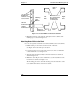
Mark this face of
the columns with
masking tape
or marker pen.
Right
Side
Left
Side
Front of
Rack
Rear of
Rack
Bottom of
HP NetServer
represents
the EIA unit
numbers on the
rack columns.
3rd Hole
From Bottom
1st Hole
From Bottom
Masking
Tape
Marker
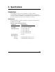
Figure 13-3. Location Marks on the Rack’s Columns
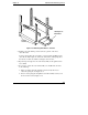
3. Mark the inside face of the left-rear and right-rear rack columns, with
masking tape, as shown in Figure 13-3.
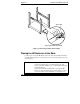
Attaching Outer-Rails to the Rack
No tools are required to attach the outer-rail assemblies to the rack columns.
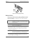
1. Pull the anti-tip foot forward out of the bottom of the rack.
See Figure 13-4 for the anti-tip foot location.
2. Lower the leveler screws on the rack’s lower four corners to make firm
contact with the floor. See Figure 13-4.
3. Align the left outer-rail assembly to the left front and rear columns as
shown in Figure 13-4.
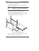
4. Match the outer-rail pins to the column holes (1st & 3rd) marked on the
front and rear columns. See Figure 13-3.
The mounting pins of the outer-rails should go into the inside face of the
rear column and front face of the front column.