
HP Netserver LP 1000r User Guide


Chapter 5 Installing Additional Boards
39
IC
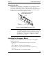
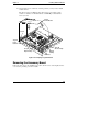
Connector
2
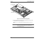
System Board (top view)
64-Bit PCI Slot (1)
Riser Board (not shown)
Figure 5-2. PCI Accessory Board Slot
NOTE Refer to "System Board Layout" in the Appendix A,
"Specifications," for connections not shown in Figure 5-2.
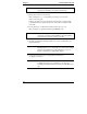
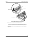
7. Lift and rotate the securing clamp up to about a 45° angle. See Figure 5-3.
The securing clamp holds the riser board in place and helps secure the PCI
board.
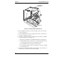
8. Remove the securing clamp from the chassis and set it aside for
re-assembly later.