HP NetServer LXr Pro8 4 GB Memory Board Installation Guide HP Part Number 5967-2103 Printed in January 1998
Notice The information contained in this document is subject to change without notice. Hewlett-Packard makes no warranty of any kind with regard to this material, including, but not limited to, the implied warranties of merchantability and fitness for a particular purpose. Hewlett-Packard shall not be liable for errors contained herein or for incidental or consequential damages in connection with the furnishing, performance, or use of this material.
Contents Preface..............................................................................................................1 Purpose of this Guide.....................................................................................1 Contents of this Guide....................................................................................1 Intended Audience .........................................................................................1 Related Documentation......................................
6 Specifications............................................................................................. 37 7 Regulatory Information.............................................................................. 39 Index ...............................................................................................................
Preface Purpose of this Guide This guide describes the steps you need to perform to install and configure the 4 GB (Gigabyte) memory board (HP Product Number D5027A) in an HP NetServer LXr Pro8.
Preface Related Documentation The following documents describe the HP NetServer LXr Pro8: • The HP NetServer LXr Pro8 User Guide • The Product and Service Reference Labels • Information Assistant on the HP NetServer Navigator CD-ROM 2
1 Introduction Verifying Contents Unpack and verify the contents of the shipping box against the Contents Checklist included with your HP NetServer LXr Pro8 4 GB memory board. If anything is missing or damaged, call your reseller.
2 Installing Memory in the 4 GB Memory Board This chapter includes guidelines and instructions for: • Powering down the NetServer • Removing the existing 4 GB memory board for a memory upgrade • Installing 128 MB SDRAM DIMMs in the specified DIMM slot configuration on the 4 GB memory board • Removing 128 MB SDRAM DIMMs and downsizing the memory configuration • Installing the 4 GB memory board • Powering up the system Installation Basics The HP NetServer LXr Pro8 accepts up to two memory boards.
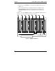
Chapter 2 Installing Memory in the 4 GB Memory Board • The memory board DIMM slots are numbered from M0 to M31 as shown in Figure 2-1. • The recommended memory configurations and the slot numbers where SDRAM DIMMs are installed are listed in Figure 2-2 and Figure 2-3. Add SDRAM DIMMs only in these quantities and in the specified slot numbers. Figure 2-1 shows the DIMM slot numbers on the 4 GB Memory Board. Board jumpers are preset to the memory board revision level.
Chapter 2 Installing Memory in the 4 GB Memory Board Figure 2-2 shows memory configurations when one 4 GB Memory board is installed. Figure 2-3 shows configurations when two 4 GB memory boards are installed. The Figures show the recommended order in which DIMM slots are filled as you add 128 MB SDRAM DIMMs to the 4 GB boards: An "X" indicates that a SDRAM DIMM is installed in each of the slots shown: Memory Upper Memory Board Slots M0 - M31 Size Quantity 0 256 MB 512 MB 1 GB 1.
Chapter 2 Installing Memory in the 4 GB Memory Board Tools Required To remove or install a memory board, first remove the satellite chassis lower fan module and the rear access panel. These tools are required for removal and installation of accessories: • Number 1 Phillips head screwdriver • An anti-static service kit (3M 8501/8502/8503 or equivalent). This kit includes a static-dissipating work surface, a chassis clip lead, and a wrist strap.
Chapter 2 Installing Memory in the 4 GB Memory Board Power LED AC Power LED DC Power Switch Figure 2-4. HP NetServer Control Panel 4. Unlock the power interlock switch at the back of the HP NetServer's rear panel by turning it clockwise (Figure 2-5). The switch turns off DC power to the HP NetServer, and also unlocks the satellite chassis. See the HP NetServer LXr Pro8 User Guide for more details on opening and closing the HP NetServer chassis.
Chapter 2 Installing Memory in the 4 GB Memory Board Power Interlock Switch Unlocked Figure 2-5. Power Interlock Switch, NetServer Rear Panel Accessing the Lower Board Cage The lower board cage holds the NetServer’s memory boards. To reach these boards, you extend the satellite chassis and remove the lower fan module and rear access panel. NOTE If the server is mounted in a rack, cables most likely run from the satellite chassis to other rack components.
Chapter 2 CAUTION Installing Memory in the 4 GB Memory Board You will need to replace the retention bracket when redocking the Satellite Chassis. The Bracket ensures correct mechanical connection. Figure 2-6. Location of the Retention Bracket 2. Stand behind the HP NetServer and grasp the two ejector handles on the HP NetServer’s rear panel. Pull both handles down firmly, and then pull the satellite toward you. Pull it out until its slides are fully extended.
Chapter 2 Installing Memory in the 4 GB Memory Board Ejector Handles Figure 2-7. Sliding Out the Satellite Chassis 2. Remove the lower fan module, as shown in Figure 2-8: a. Grasp the handles on either end of the fan module and push them toward each other. b. While continuing to push on the handles, pull the fan module toward you. The module slides backward off its mounting rails.
Chapter 2 Installing Memory in the 4 GB Memory Board Base Chassis Satellite Chassis Handles Lower Fan Module Figure 2-8. Removing the Lower Fan Module 3. Remove the NetServer’s rear access panel, as shown in Figure 2-9: a. Loosen the three captive screws that fix the panel in place. b. Lift the panel straight up and toward you.
Chapter 2 Captive Screws Installing Memory in the 4 GB Memory Board Rear Access Panel Figure 2-9.
Chapter 2 Installing Memory in the 4 GB Memory Board Removing the Existing 4 GB Memory Board The HP NetServer has one 4 GB memory board installed. Follow these steps to remove the existing memory board for a memory upgrade: 1. After removing the rear access panel, locate the existing 4 GB memory board (Figure 2-10). 2. On the memory board, open the two retaining clips toward you. Base Chassis Satellite Chassis Retaining Clips 4 GB Memory Board Figure 2-10. Removing the Memory Board 3.
Chapter 2 Installing Memory in the 4 GB Memory Board Installing 128 MB SDRAM DIMMs on the 4 GB Memory Board Follow these steps to install a 128 MB SDRAM DIMM in a slot on the 4 GB memory board. CAUTION Use only 128 SDRAM DIMMs acquired from HP. Contact HP Customer Support for a list of qualified 128 MB SDRAM DIMMs. HP will not support configurations that use non-HP SDRAM DIMMs. 1. If you are installing a new memory board, remove the 4 GB memory board from its anti-static container. 2.
Chapter 2 Installing Memory in the 4 GB Memory Board 4. Locate the slot where you will install the 128 SDRAM DIMM, and spread the two DIMM retaining clips outward. (Figure 2-12). Retaining Clip Retaining Clip Figure 2-12. Installing a DIMM Module 5. Align the notches on the SDRAM DIMM with the notches on the socket. 6. Hold the SDRAM DIMM so that the front edge faces straight down into the connector (at a 90° angle to the memory board).
Chapter 2 Installing Memory in the 4 GB Memory Board 7. Insert the SDRAM DIMM carefully into the desired slot. The retaining clips will grasp the SDRAM DIMM automatically if it is inserted properly. CAUTION Do not rock the SDRAM DIMM into place, but apply firm and even pressure (significantly more than you would when installing SIMMs). If a gap exists between the retaining clips and the SDRAM DIMM module, remove the module and repeat steps 5-7. 8.
Chapter 2 Installing Memory in the 4 GB Memory Board 7. Place the DIMM in its anti-static container. 8. Repeat steps 5-7 for as many SDRAM DIMMs as you need to remove. 9. If necessary, remove SDRAM DIMMs and reinstall in new slots to match the DIMM slot configuration for the downsized memory. (See Figure 2-2.) CAUTION Close all retaining clips on the 4 GB memory board before inserting it into your NetServer. This includes clips on empty slots as well as those on slots containing DIMMs.
Chapter 2 Installing Memory in the 4 GB Memory Board 3. Being careful not to touch board components, ease the first memory board into the top memory board slot and close the retaining latches on the front of the memory board to seat it snugly (Figure 2-13). Base Chassis Satellite Chassis Memory Board Slots Retaining Clips 4 GB Memory Board Figure 2-13. 4 GB Memory Board Installation 4. Install the second memory board in the lower slot.
Chapter 2 Installing Memory in the 4 GB Memory Board 6. Reattach the lower fan module: a. On each side of the back of the fan module are two slots. Line these slots up with the flanges on the fan’s mounting rails. b. Push the fan module onto the mounting rails until it clicks into place. 7. Reattach the satellite chassis to the base chassis: a. When you finish servicing the HP NetServer, move to the front of the server and unlatch all four power supplies. (If the front bezel is in place, remove it.) b.
Chapter 2 Installing Memory in the 4 GB Memory Board d. Let go of the release latches. Now grasp the ejector handles and push the satellite chassis the rest of the way onto the base. Be careful to keep the ejector handles in the "down" position. e. When the satellite chassis slides as far forward as it can go, push the ejector handles up. f. Replace the retention bracket as shown in Figure 2-6. g. At the front, relatch the power supplies. Power-Up Procedure 1.
Chapter 2 Installing Memory in the 4 GB Memory Board The HP NetServer cannot start unless the Power Interlock Switch is in this position Figure 2-15. Power Interlock Switch, HP NetServer Rear Panel 4. Turn on the monitor.
3 Troubleshooting Diagnostics Overview A set of diagnostics procedures and reporting facilities points you towards a troubleshooting solution if problems occur. The memory controller corrects minor (single-bit) errors in DIMM functioning. Errors are detected and reported both during boot-up testing and during run time. More serious, multiple-bit errors may require the user to replace a defective DIMM.
Chapter 3 Troubleshooting Standard BIOS Error Messages Several different situations generate visual or auditory error messages which appear in the Event Log Report Utility: • No memory board detected. If a memory board is not installed, the system generates 11 beeps and halts. • Memory board detected, but no DIMMs found. If no DIMMs are installed on the board, you will hear three beeps and the system hangs. • Mixed DIMM sizes. HP will not support DIMMs of varying sizes.
Chapter 3 Troubleshooting • ECC Multiple-bit errors (two bits or more). Multiple-bit errors, which are extremely rare, may cause the system to halt or display a memory parity error. If this occurs, take the following steps: 1. Cycle the system power. 2. During the power-on self test (POST), press the ‘D’ key to test memory. ◊ If the memory test passes, then the memory failure could be a soft ECC error. Reboot the system and reactivate your applications.
4 Service and Support Please refer to the "Troubleshooting" chapter for the steps to follow before calling for service.
Chapter 4 Service and Support Europe For hardware repair or telephone support in Europe, contact either: • Participating Service Authorized HP Personal Computer Reseller or • HP Customer Support Center (Netherlands) for the following countries: 30 Austria: 0660 6386 Belgium (Dutch): 02 626 8806 Belgium (French): 02 626 8807 Denmark: 3929 4099 Finland: 02 03 47 288 France: 04 50 43 9853 Germany: 0180 525 8143 Ireland: 01 662 5525 Italy: 02 2 641 0350 Netherlands: 020 6068751 Norway:
Chapter 4 Service and Support Asia/Pacific For hardware service and telephone support, contact either: • A participating Reseller or • HP Customer Support Center: Australia: +61 (03) 9272 8000 China: +86 (10) 6505 3888 Hong Kong: 800 967729 (toll free) India: +91 (011) 682 6035 Indonesia: +62 21 350 3408 Japan: +81 3 3335 8333 Korea: +82 2 3270 0700 (Outside Seoul: 080 999 0700) Malaysia: (03) 295-2566 New Zealand: 0800 445 543 (toll free) Philippines: +63 2 867 3551 Singapore: +65 27
Chapter 4 Service and Support Ordering HP Cables, Drive Trays, and Technical Publications If you need more technical information, Hewlett-Packard publishes other references that you can order from HP, such as the HP NetServer Product Line Service Handbook. Service information and reference documents, such as the Dealer Configuration File Creation Guide (CFG), are also available in Information Assistant on the HP NetServer Navigator CD-ROM.
Chapter 4 Service and Support Contacting HP Regional Headquarters Should you need to contact Hewlett-Packard, check your local telephone directory for the HP Sales and Service Office near you. If you cannot locate an HP office, contact one of the Worldwide HP Marketing Headquarters listed here: NOTE Please note that sales and support for this Hewlett-Packard product may not be currently available in all regions listed below. Asia/Pacific Headquarters Hewlett-Packard Asia Pacific Ltd.
Chapter 4 Service and Support Joining CompuServe To open a CompuServe account or to obtain information on access numbers and charges in your country, you can purchase a CompuServe startup kit at a computer software reseller or you can contact CompuServe directly. Mention “Representative 133” to receive a free introductory membership with a free usage credit. CompuServe Europe CompuServe Postfach 11 69 P.O.
5 Hardware Warranty This HP NetServer accessory is covered by a limited hardware warranty for a period of one year from receipt by the original end-user purchaser. Once installed in an HP NetServer, this accessory may carry the longer of either a one-year warranty or the remainder of the warranty period for the NetServer in which it is installed. This accessory may be serviced through expedited part shipments.
6 Specifications Electrical Power Budget Components are powered at +3.3 and +5 volts. Power Dissipation +3.3 V +5.0 V 77.
7 Regulatory Information DECLARATION OF CONFORMITY according to ISO/IEC Guide 22 and EN 45014 Manufacturer’s Name: Hewlett-Packard Company Manufacturer’s Address: 5301 Stevens Creek Blvd.
Index B BIOS Post Test Memory Count Display, 25 I Installing SDRAM DIMMs, 16 Installing the Memory Board, 19 C Contents Checklist, 3 L LXr Pro8 NetServer systems, 1 D Dual In-Line Memory Module (DIMM), 3 M Memory capacity, 1 Mixing DIMM sizes and speeds, 26 E ECC (Error Checking and Correction) Errors Single-Bit Errors, 26 ECC Single- and Multiple-Bit Errors, 26 R Readme File, 3 Removing a 128 MB SDRAM DIMM Module, 18 H help CompuServe, 34 from Hewlett-Packard, 33 S Standard BIOS Errors, 26 T Troub