
HP Netserver Service Handbook, Volume 1 - Low End


81
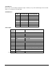
HP Rack Storage/8 Rack Guidelines
ALWAYS refer to the HP NetServer Rack Installation Road Map to be sure that you are proceeding
correctly. Failure to perform this installation in accordance with the Road Map could result in significant extra
installation effort.
The HP Rack Storage/8 enclosure is supported in the rack by two support rails that are attached to the
framework of the rack. Since the HP Rack Storage/8 enclosure weighs approximately 58.9 lb. (26.8 kgs)
without hard disk drives, it is advisable that no less than two people lift the unit to place it on the installed
support rails.
Observe the following guidelines:
• Mass storage devices are susceptible to mechanical shock and can be damaged by a drop as
small as a quarter of an inch. Never ship the HP Rack Storage/8 with hard disk drives mounted
in the enclosure.
• Do not dispose of the filler panel. If you decide to operate the storage system with the empty
bay, it must be covered with a blank panel cover to ensure proper cooling and electronic
radiation compliance.
• When the hot swap disk module stops, it is not flush with the bezel; the module extends about
one-quarter inch from the bezel. When you lock the module in place, the module moves to the
final position, flush with the bezel. Forcing the module past the first stop may damage the
module.
• The module drive platters may still be spinning and may be warm to touch.
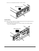
• For proper cooling the HP Rack Storage/8 uses two fan units located on each side of the
enclosure next to the power units. Each unit is a portable and hot-swappable. The same model
of the fan unit is used on both sides of the enclosure. From the back of the rack, the fan unit on
the right side has the latch lever to the top. On the left side, the latch lever is at the bottom.
• Do not operate the HP Rack Storage/8 for extended periods with a fan unit removed. Doing so
could cause overheating and failure of the disk drives.
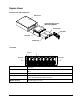
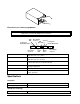
Power Supply Units
Each power supply contains one 250 watt, redundant switching, regulated power supply. In addition each
unit has a power-factor correction, auto-ranging AC input and is able to operate at low line conditions (from
90 VAC to 135 VAC) or at high line conditions (180 VAC to 257 VAC) at either 50 Hz or 60 Hz.
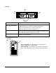
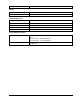
NOTE The orientation of the finger ring on Locking and Release Mechanism should always
be toward the outside of the enclosure. However, you can change the orientation of
the ring by removing the screw on the pivot point and flipping the mechanism end to
end.