HP NetServer Product Line Service Reference Guide Volume 2 Mid-Range Version 2 Last Updated: June 2001
Notice The information contained in this document is subject to change without notice. Hewlett-Packard makes no warranty of any kind with regard to this material, including, but not limited to, the implied warranties of merchantability and fitness for a particular purpose. Hewlett-Packard shall not be liable for errors contained herein or for incidental or consequential damages in connection with the furnishing, performance, or use of this material.
Table of Contents HP NetServer LC System Views Front Bezel and Cover System Board System Board Connectors, Switches, and Jumpers System Board Connector J7 SW1 Switch and Default Settings Processor Boards Intel 486 Processor Board with Optional 256 KB Cache Pentium™ Processor Board 5/100, 5/133, 5/166 Pentium™ Processor Board Memory Video Memory - DRAM Flexible Disk Drive Guidelines Exploded View Parts List Keyboards Power Cords Specifications 1 1 2 2 3 4 4 5 5 5 6 6 7 7 8 8 10 10 11 HP NetServer LC 3 Syst
Memory Processor Board LED Blink Codes Boot Device Priority Cabling Configurations Configuring Switch Settings on the Hot Swap Subsystem Hot Swap Subsystem SCSI Address Settings Exploded Views Parts List Mass Storage Cables Keyboards Power Cords Specifications 32 33 34 36 37 38 39 41 42 43 43 43 HP NetServer LE System Views Installation View Exploded View HP NetServer LE Parts List HP NetServer LE Keyboards HP NetServer LE Power Cords System Board and Connectors System Board Jumpers and Switches Processor
HP NetServer LH Plus Parts List HP NetServer LH Plus Mass Storage Cables HP NetServer LH Pro Exploded Views HP NetServer LH Pro Replaceable Parts List HP NetServer LH Pro Mass Storage Cables HP NetServer LH Keyboards HP NetServer LH Power Cords HP NetServer LH System Board and Connectors HP NetServer LH System Board Connectors, Switches, and Jumpers HP NetServer LH Plus/Pro System Board and Connectors HP NetServer LH Plus / LH Pro System Board Connectors System Switches and Jumper Descriptions HP NetServer
Hot-Swap Hard Disk Drive LED Status and Activity Indicators System Board System Switches Cabling Cables and Part Numbers Specifications 113 113 114 114 115 115 HP NetServer LM System Views F Exploded View Parts List HP NetServer LM Keyboards HP NetServer LM Power Cords System Board System Board Jumper Locations System Board Jumper Settings Memory Video Memory - DRAM HP NetServer LM System Updates Factory Installed SCSI Hard Drive 1740 SCSI Host Adapter Configuration Selecting Primary SCSI Channel SCSI BIO
Control Panel Connector J1 Mass Storage Indicator Lights Cover Exploded Views Parts List Keyboards Power Cords Mass Storage Cables System Board System Board Connectors System Switches and Jumpers Memory Configuration Video Memory - DRAM Boot Device Priority Cabling Configuring Switch Settings on the Hot Swap Subsystem Hot Swap Subsystem SCSI Address Settings Specifications 144 145 146 147 149 150 151 151 152 153 153 154 155 155 155 158 159 159 Notes 161 Index 165 vii
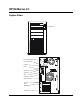
HP NetServer LC System Views Control Panel Line Voltage Selection Switch Power Cable Clamp Keyboard Mouse Serial Port B Serial Port A Video Parallel Port SCSI External Port PCI Slot 6 PCI or EISA/ISA Slot 5 EISA/ISA Slot 1 1
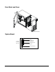
Front Bezel and Cover Bezel handles System Board Keyboard IO Panel Connectors Mouse Serial port B Serial port A Parallel port LPT1 Side view Monitor External SCSI port 2
Control panel cable connector Power P1 & P2 Battery connector Power Supply On Power Adapter (HP Remote Assistant) Flexible disk drive cable connector IDE disk drive cable connector ROM Internal SCSI connector Pin 1 Power P3 & P4 Mounting pin Main fan connector SW1 system board switches Slot 3 - PCI Processor Board Slot 2 - PCI Hard disk activity light Slot 5 - EISA/ISA Slot 1 - EISA/ISA System Board System Board Connectors, Switches, and Jumpers The table below explains the system board markin
System Board Connector J7 This connector is used by the HP Remote Assistant Accessory -- a 32-bit EISA Bus Master board used to remotely monitor server functionality. For additional information on this product, see the documentation that comes with it. When you install the HP Remote Assistant cable, you will need to remove the jumper on PS REMOTE and PS ON. If you remove HP Remote Assistant from the server, remember to re-install the jumper.
5 PASSWORD ENABLE: Enables or erases the power-on password maintained in NVRAM. ON: Power-on password functional. OFF: Erases the current power-on password. ON 6 SMI# ENABLE: Not used - leave in default position OFF: Prevents SMI interrupt. OFF 7 IO CTRL ENABLE: Enables or disables onboard flexible disk drive controller, IDE controller, and serial and parallel ports. ON: I/O controller enabled. OFF: I/O controller disabled. ON 8 VIDEO ENABLE: Enables or disables built-in video.
Jumper Setting (Not on 66 Board) /100, /133 /75 133 VRE 75/100 VR Bank 0/1 Bank 2/3 Bank 4/5 5/100, 5/133, 5/166 Pentium™ Processor Board Before installing this board, verify that jumper setting J1 is set to VRE and jumper setting J2 is set to the correct speed for your chip as shown in the illustration below. 2 4 6 J1 J2 1 3 5 100 133 166 2 4 6 2 4 6 2 4 6 VRE J1 J2 VR 1 3 5 1 3 5 1 3 5 Memory The Intel 486 processor board has 8 MB of single-density base memory installed.
• You must install SIMMs in pairs (called banks) of matching size; however, the banks can be of different sizes. • To achieve large memory configurations (greater than 144 MB) with the Pentium processor, you must remove and replace the SIMMs that are already installed in the server. • If you obtain SIMMs from other sources, for 16 MB and 32 MB SIMMs, the speed must be 60 or 70 ns. Video Memory - DRAM No additional video memory can be installed in the HP NetServer LC. Current video memory is 512 KB.
Exploded View 8 7 9 6 5 10 4 3 11 12 2 1 14 13 15 Parts List Fig 8 Description Replacement Exchange 1 Front bezel 5063-5617 2a 535 MB SCSI HDD D2075-60003 D2075-69001 540 MB SCSI HDD D2386-63001 D2386-69001 2b 1 GB SCSI HDD D2076-63102 D2076-69002 2c 2.1 GB HDD D2077-63100 D2077-69001 3 1.44 MB 3.
Fig Description Replacement Exchange 5 Chassis with door, fan, mass storage cage 5064-0744 6 Control Panel PCA 5063-5607 7 Battery (4.
Fig Description Replacement * DeskDirect NIC J2973-61001 * HP Navigator CD-ROM D3600A ** * NS Server Saver Test Disk 5010-8878 * Diagnostic Assistant Diskette 5063-8343 ** Exchange * This part is not on an exploded view. * * This part number is constantly revised. When you order the CD-ROM, you will be sent the latest revision.
Specifications Power Supply 100 to 127 VAC ~ 6.0 A or 200 to 240 Volts AC ~ 3.14 A at 50 to 60 Hertz Power Availability 224 watts peak, 200 watts continuous Power Consumption 301/351 watts peak with 110-volt line maximum voltage 291/337 watts peak with 220-volt line maximum voltage System Dimensions 16.7 in. high x 9.3 in. wide x 17.6 in. deep 42.4 cm high x 23.6 cm wide x 44.7 cm deep System Weight Weight: 40 pounds Model 1* (18.
HP NetServer LC 3 System Views Power Switch Keyboard Lock Serial Port B Serial Port A Fan Parallel Port Mouse Port Keyboard Port Lock Monitor Flexible Disk Drive Management Port EIDE CD-ROM Shelf 3 Fan Hot Swap Drive Bay Power Hot Swap Drive Bay Lock Front Control Panel Power Switch Turns the NetServer on and off. Note that when the NetServer is turned off, the power to the internal circuitry and mass storage devices is disabled; however, AC power is still applied to the power supply.
Covers CAUTION The covers are an integral part of the server. The server must be operated with the covers in place to ensure proper airflow for continued reliability and to maintain compliance with radio frequency interference and safety standards.
Memory There are four DIMM sockets on the system board for memory expansion Follow these simple rules when you plan to install additional memory DIMMs: • Use only HP DIMMs listed on the Technical Reference Label located inside the HP NetServer top cover, in Information Assistant, or in Order Assistant. • DIMMs can be 32 MB, 64 MB, or 128 MB in any combination. • DIMMs can be installed in any order in any of the four DIMM sockets.
Video Memory Expand video memory by installing two 256 K x 16 (512 KB), 70 Ns, 40-pin SOJ package DRAM ICs. CAUTION Install the chip in the correct orientation. Failure to do so will destroy the DRAM.. Video Slots Boot Device Priority The boot device priority is controlled by the Boot Device Ordering submenu of the Configuration menu of the Setup utility.
DIMM Slot LED Blink Codes System Board LED 0 LED 1 LED 2 LED 3 Processor Error Codes Processor errors are indicated by blinking patterns of the DIMM slot LEDs that alternate at 1 Hz, as listed below: Processor Error Status Indications ² = LED off O = LED on LED LED LED LED 0 1 2 3 ² O O O O ² ² ² O ² O O ² O ² ² ² O O ² O ² ² O O O ² ² ² ² O O Error Condition Action Voltage Regulator Module for Primary CPU Bad Check that primary voltage regulator module (VRM) is corre
Exploded Views 2 15 1 14 13 12 11 10 3 4 5 7 8 9 18 6
21 20 19 18 22 23 17 16 19
27 26 28 25 29 24 30 20
Parts List Fig Description Replacement Exchange 1 Chassis Assembly 2 Top Cover 5064-1987 3 Side Cover 5064-1986 4 Cage Assy, Hot-Swap Mass Storage 5063-5671 5 Light Pipe 5041-1099 6 Backplane PCA, Hot-Swap Cage D3604-63003 7 Hot Swap Cage Bezel 5042-2108 8 Hot Swap Cage Bezel lock 5064-3503 9 tray, Hot Swap, D3349B D3583-69004 10 5 1/4 inch tray, HDD D2198B 3 pack C2260-60078 Single 11a 4.2 GB SCSI HDD D4910-63001 D4910-69001 11b 9.
28 Control Panel PCA 5064-1979 29 Front Bezel Assy.
Denmark 8120-2956 Switzerland 8120-2104 Europe 8120-1689 United Kingdom 8120-1351 Mass Storage Cables Cabling Label Location A System backplane SCSI connector to upper-shelf SCSI devices 5-connector, wide (68-pin) SCSI cable w/built-in terminator 5183-2412 B System backplane IDE connector to IDE devices (CDROM or other) 3-connector IDE cable 5183-2411 C System backplane floppy connector-to-floppy disk drive 2-connector floppy disk cable 5183-2410 D System backplane (or NetRAID control
System Board Secondary Processor Socket (Terminator Installed In Dual-Ready Configurations) Retaining Latches * Processor Fan Secondary VRM Socket * J20: N/C System Configuration Switches Primary Processor Primary VRM * J17: N/C * J25: 100 MHz Diagnostic LEDs * J26: N/C Memory DIMM Sockets 01 2 3 Battery 0 1 Video Memory Upgrade Sockets 2 3 * Cable connectors labeled with function. Configuration jumpers labeled with default setting. N/C = no jumper header or cable installed.
Specifications Operating Temperature 5°to 35°C (41°to 95°F) Non-operating Temperature -40° to +70° C (-40° to +158° F) Operating Humidity (noncondensing) 20% to 80% relative humidity Non-operating Humidity (noncondensing) 90% relative humidity Operating Altitude 3,045 m (10,000 ft) Non-operating Altitude 12,180 m (40,000 ft) Height 530 mm (21 in) Width 217 mm (8.6 in) Depth 580 mm (23 in) Weight 22 - 25 kg (48 - 55 lb.
HP NetServer LD Pro System Views Flexible Disk Control Panel CD-ROM Hot Swap Subsystem Keyboard, mouse, serial, and display connectors External SCSI port connectors 27
Control Panel H ard D is k A c ti vity L i g h t Ye ll o w = E m b e d d ed SC SI o r ID E b u s a c t ive Po w er -On L i g h t Gr ee n = p o w er i s o n K ey b o ar d L o c k L ig h t Yel lo w = k ey b o ar d is l o c k e d K ey b o ar d L o c k B u tto n P o w e r B u t to n Re s et B u t to n Power Button Turns the HP NetServer on and off.
System Board and Connectors PS4/P4 Flexible Disk Connector PS3/P3 PS1/P1 Power Supply Enable Connector PS2/P2 Control Panel J27 Connector HP Remote Assistant Connector IDE Disk Drive Cable Connector Battery Connectors Power Supply Cable Connectors I/O Panel Connectors Trident 9000i Processor Board Connector J16 PS4 3v Pwr Module J36 SW1 Default Settings: Off Temperature Sensor AIC 7880 Slot 9 - PCI-0 Slot 8 - PCI-1 On 1 2 3 4 5 6 7 8 Flash Write Enable Boot Lock Disable Config Valid Config
System Board Connectors, Switches, and Jumpers The table below explains the system board markings for all connectors.
System Switches and Jumper Descriptions Remote Assistant Connector J25 This connector is used by the HP Remote Assistant Accessory, a 32-bit EISA Bus Master board used to remotely monitor server functionality. For additional information on this product, see the documentation that comes with it. When you install the HP Remote Assistant cable, you will need to remove the jumper on PS REMOTE and PS ON. If you remove HP Remote Assistant from the server, remember to re-install the jumper.
Switch 3 Function CONFIG VALID: Saves or erases the current configuration information in NVRAM and CMOS. Default ON ON: Saves the current configuration. OFF: Erases the current system configuration. 4 CONFIG UNLOCK: Prevents or allows the current system configuration maintained in NVRAM and CMOS to be changed. ON ON: Unlocked. Allows the current system configuration to be changed. OFF: Locked. Prevents the current system configuration from being changed.
Processor Board LED Blink Codes The processor board in the NetServer LD Pro contains LEDs that can indicate memory errors and processor errors. When a memory error exists, the LEDs are either on, off, or flash repeatedly a constant memory error code. The table below describes each of these codes. If the memory error indicates a failed DIMM, replace the DIMM. When a processor error exists, the LEDs alternate between two codes (i.e., ON-OFF-OFF-OFF and OFF-ON-ON-ON).
LED Processor Error Codes Alternating LED Codes: LED LED LED LED 0 1 2 3 Definition Action ON-OFF-OFF-ON & OFF-ON-ON-OFF Processor chip overtemperature Check fans for function.
If you have a system with a mixture of PCI and ISA or EISA boards perform the following: 1. Install the PCI controller board in slot 9. 2. Go to the EISA Configuration Utility. 3. Select "Step 3: View or edit details." 4. Select "PCI 9 - PCI SCSI Controller" and press F6. 5. Set the top Memory Address resource to "0C8000h" and press F10. 6. Press F7 and select "Lock/unlock boards." Select the PCI board in slot 9 and lock. 7. Exit and save the configuration.
NOTE In order to optimize PCI board BIOS installation, you need to leave the largest open range of memory possible. Group the EISA and ISA board BIOSs at either the beginning or end of the 0C8000h through 0DFFFFh range. Cabling Configurations Duplex, Non-Disk Array Model with Internal Controller This is a standard mass storage configuration as shipped from HP. NOTE If you are installing Ultra SCSI mass storage devices in this NetServer, you must enable Ultra SCSI.
Duplex Disk Array Configuration with Dual Channel PCI Controller Board This is one of several possible optional mass storage configurations. You are not limited to the configurations shown on this CD-ROM; this is only given as an example.
Off On 1 2 3 4 5 6 Technical Information Label with configuration information Always set switches 1, 2 and 6 to Off. Switch 1 Function Settings 2 Always set to Off 2 I C Bus Setting 2 I C Bus Setting Always set to Off 3 High/Low Addresses On Sets drives to upper eight SCSI addresses. Sets SCSI addresses for upper or lower eight addresses Off Sets drives to lower eight SCSI addresses. On Sets middle shelf in the cage (shelf 2) to SCSI ID 0. Off Sets middle shelf to SCSI ID 2.
On Off Shelf 1 = ID 9 Shelf 2 = ID 10 Shelf 3 = ID 11 On On Shelf 1 = ID 9 Shelf 2 = ID 8 Shelf 3 = ID 11 Exploded Views 1 3 2 4 8 5 6 10 15 11 18 12 16 13 9 21 7 17 19 20 14 39
22 25 1 26 28 23 27 29 43 32 1 34 35 33 36 37 38 40
Parts List NOTE The part numbers in the list were the ones that were available at the time of publication. Part numbers may change after publication. HP's parts price list database will generally contain a reference to the revised part number. If a system board needs to be replaced, remove processor board and any added accessory boards, and keep them with the server under repair. * This part is not on an exploded view. Fig Description Replacement Exchange 1 Chassis Assembly 2 1.44 MB 3.
Fig Description Replacement Pentium P6 180 Processor Chip 1821-3450 Pentium P6 200 Processor Chip 1821-3449 Dual Pentium Pro/200 processor board upgrade kit 27 Exchange D4959A Heat Sink 5182-9378 Heat Sink Clip 5182-9344 29a 16 MB - DIMM D4294-63001 D4294-69001 29b 32 MB - DIMM D4295-63001 D4295-69001 29c 64 MB - DIMM D4296-63001 D4296-69001 29d 128 MB -DIMM D4297-63001 D4297-69001 32 Rear Fan Cage 5064-0701 33 Power Supply 5064-0795 34 Control Panel Bezel 5063-8380 35
2 B1 I C cable, system board to hot-swap backplane 2 3-pin I C cable 5182-4535 Keyboards Language HP Part Number Language HP Part Number US D4950-63001 Danish D4950-63016 Arab/French D4950-63025 Fr-Canadian D4950-63002 Portuguese D4950-63027 German D4950-63003 Cyrillic D4950-63030 Spanish D4950-63004 Belgian/Flemish D4950-63014 French D4950-63005 Italian D4950-63017 Norwegian D4950-63009 Arab/English D4950-63020 Swiss D4950-63011 Korea/Hangu D4950-63021 Swedish D4950
Server Footprint 369 x 474.71 mm (14.53 x 18.89 in) System Weight 50-70lb (22.7-31.8kg), depending on configuration Keyboard Height 3.4 cm (1.4 in) Width 46.8 cm (18.4 in) Depth 19.8 cm (7.8 in) Weight 1.9 kilograms (4.2 lb.) Cable Length Keyboard cable 3 m (9.
HP NetServer LE System Views Control Panel Detail Reset Desktop Position: Lock 5 4 3 2 1 SERIAL B SER IAL A SERIAL B Mouse Parallel SC SI SERIAL A SCSI Video Keyboard 45
Installation View 46
Exploded View 3 12 13 14 1 15 2 9 4 6 5 8 11 10 7 HP NetServer LE Parts List NOTE Fig 1 The part numbers in the list were the ones that were available at the time of publication. Part numbers may change after publication. HP's parts price list database will generally contain a reference to the revised part number.
Fig 3 Item Description Exchange Replacement 4 MB SIMM 80 ns 1x4 MB module D2156-69001 D2156-63001 8 MB SIMM 80 ns 1x8 MB module D2152-69001 D2152-63001 16 MB SIMM 70 ns 1x16 MB module D2297-69001 D2297-63001 32 MB SIMM 70 ns 1x32 MB module D2298-69001 D2298-63001 N/A D2035-63004 4 3.5" 1.44 MB Floppy Disk Drive 5a 535 MB SCSI-2 Disk Drive D2075-69001 D2075-60003 5b 1000 MB SCSI-2 Disk Drive D2076-69001 D2076-63102 5c 3.5" Drive Tray D2198A 5d 5.25" CD-ROM tray D2199A 6 5.
Spanish C1405-60304 Korea/Hangul C1405-60321 French C1405-60305 Taiwan C1405-60323 Norway C1405-60309 Arab/French C1405-60325 Swiss C1405-60311 Portuguese C1405-60327 Swedish C1405-60312 Cyrillic C1405-60330 UK C1405-60313 Japan/Kanji C1414-60001 HP NetServer LE Power Cords Country HP Part Number Country HP Part Number Australia/New Zealand 8120-1369 India/South Africa 8120-4211 Canada/United States 8120-1751 Japan 8120-4753 Denmark 8120-2956 Switzerland 8120-2104 Eur
System Board Jumpers and Switches The following table explains all connector points, sockets, and switches on the system board. Num. Purpose Num.
Memory Configuration You can install any HP supported 4 MB, 8 MB, 16 MB, and 32 MB SIMMs in any socket and any arrangement. Video Memory - DRAM Install two additional DRAM chips to upgrade the server to 512 KB of RAM which lets the display use resolutions of 640x480 with 256 colors and 800x600 with 256 colors. Use video memory DRAM chips that are 16-pin DIP (Dual Inline Package) 256 KBx4 Fast Page Mode DRAM and run at 80 nanoseconds or faster.
2. Make a backup copy of your current CONFIG.SYS file by entering; COPY CONFIG.SYS CONFIG.BAK 3. Copy the SET640K.SYS file from NetServer #2 diskette to NetServer #1 diskette by entering; COPY B:SET640K.SYS A:\ (If you do not have a second flexible disk drive, DOS treats drive A as both drive A and drive B and prompts you to insert disks.) 4. Using the editor of your choice, modify the CONFIG.SYS file so that SET640K.SYS file is the first file on line 1, as shown above. 5.
HP NetServer LF System Views Control panel Mass storage shelf 1 (flexible disk drive) Mass storage shelf 9 Keyboard Mouse Serial port B Serial port A Parallel port LPT1 Monitor External SCSI port Slot 9 - PCI Slot 8 - PCI Slot 7 - EISA/ISA Cover screws (5) Slot 1 - EISA/ISA 53
Control Panel Reset button Hard disk activity lights Keyboard lock light Power-on light 1 Power button Reset Keyboard lock button Power button Turns the server on and off. Note that when the server is turned off, the power to the internal circuitry and mass storage devices is disabled; however, AC power is still applied to the power supply. Always disconnect the power cord before removing the cover. Power-on light Green when the server is on. Reset button Restarts the server.
Exploded Views 1 3 4 5 2 55
14 13 12 10 11 16 9 15 7 8 6 56
Parts List NOTE The part numbers in the list were the ones that were available at the time of publication. Part numbers may change after publication. HP's parts price list database will generally contain a reference to the revised part number. If a system board needs to be replaced, remove the ROM chip, processor board, any added accessory boards, and keep them with the server under repair.
Fig Description Replacement * Internal IDE-HDD Cable 5182-0016 * LF SCSI Cable 5182-0066 * LF SCSI terminator (Slick) 0960-0888 * Diagnostic Assistant Diskette 5011-1941 Exchange * Not on exploded view ** Directly replaces 486/66 Processor Board in later model systems. For earlier systems (Serial No.
Processor Boards New 486/66 Processor Board CPU TYPE DX2 / DX4 DX2D Cache module installation J5 Bank 0 Bank 1/2 Bank 3/4 J4 J2 MULTI TRIPLE DOUBLE CPU VOLTAGE SELECT DX2/66 J4, J5 are in these positions for both DX2/66 and DX4/100 CPU's DX4/100 Old 486/66 Processor Board Bank 3/4 J1 J2 J3 Bank 1/2 Bank 0 Note: No options on the Pentium/66 Board System Board Keyboard IO Panel Connectors Mouse Serial port B Serial port A Parallel port LPT1 Side view Monitor External SCSI port 59
Flexible disk drive cable connector Power Supply On connector Control panel cable connector Battery connector IDE disk drive cable connector Remote power supply connector Power supply cable connectors I/O panel connectors SW1 switch External SCSI connector ROM Slot 9 - PCI Processor board slot Fan Connector Slot 7 - EISA/ISA Internal SCSI connector Slot 1 - EISA/ISA Connectors Connector Number Connector Number IDE disk drive cable J21 Flexible disk drive J22 Keyboard J25 Mouse J25 Vide
NC 3.3V NC GND GND PS REMOTE PS ON SW1 Switch and Default Settings 1 2 3 4 5 6 7 8 FLASH WRITE ENABLE BOOT LOCK DISABLE CONFIG VALID CONFIG UNLOCK PASSWORD ENABLE SMI# ENABLE IO CTRL ENABLE VIDEO ENABLE ON Switch Function Default 1 FLASH WRITE ENABLE: Enables or disables one of the two levels of flash ROM write protection (the other level of protection is controlled by the HP Update Utility). ON: The BIOS can be updated by the HP Update Utility. OFF: The BIOS is locked and cannot be updated.
Memory Memory for the HP NetServer LF is installed on the processor board. The Intel 486 processor board has 8 MB of single-density base memory installed in bank 0. This memory is not customer removable and can only be single-density. There are two banks (four sockets) available for expansion memory which can be single or double density. The maximum memory supported is 136 MB (4 x 32 MB + 8 MB). The Pentium processor board has 16 MB of removable base memory installed.
HP NetServer LH System Views Flexible Disk Control Panel CD-ROM Hot Swap Subsystem Keyboard, mouse, serial, and display connectors SCSI port connectors HP NetServer LH Pro 63
Keyboard, Mouse, serial, and display connectors Keyboard, Mouse, serial, and display connectors SCSI port connectors SCSI port connectors HP NetServer LH 64 HP NetServer LH Plus
Control Panel H a r d D i s k A c t i vi t y L ig h t 2 Ye l l o w = E m b e d d e d S C S I B b u s a c tive H a r d D is k A c ti vi t y L ig h t 1 Ye l l o w = E m b e d d e d S C S I A o r ID E b u s a c t i v e K ey b o ar d L o c k L ig h t Ye l l o w = k e y b o ar d is lo c ke d P o w e r -O n L i g h t G reen = p o w er is o n K ey b o ard L o c k B u tto n P o w e r B u tt o n R e s et B u t t o n The following list describes each item on the control panel.
Cover CAUTION 66 The cover is an integral part of the server. The server must be operated with the cover in place to ensure proper airflow for continued reliability and to maintain compliance with radio frequency interference and safety standards.
HP NetServer LH Exploded Views 3a 2 3b 4a 5 4b 6 8 1 7 13 9 10 14 16 17 18 15 11 19 TO DISK ARRAY 12 20 67
21 1 22 23 24 27 25 26 1 29 30 34 31 32 33 68
HP NetServer LH Parts List NOTE The part numbers in the list were the ones that were available at the time of publication. Part numbers may change after publication. HP's parts price list database will generally contain a reference to the revised part number. If a system board needs to be replaced, remove processor board and any added accessory boards, and keep them with the server under repair. * This part is not on an exploded view.
Fig # Description Replacement Bracket-CPU Mount Exchange 5002-3243 26 HP DAC Controller Board 27 PCI Hold Down Bracket 5002-3279 29 LH Control Panel Bezel 5063-0381 30 LH Control Panel PCA 5063-0382 31 Cardguide Assembly 5063-5697 32 Fan Assembly 3160-1004 33 Chassis Foot 5041-1082 34 Power Supply - 350W 5063-5690 * LH System ROM D3353-80204 * LH P75 CPU Chip 1821-1717 * LH P100 CPU Chip 1821-1669 * LH ZIF Heat Sink 1205-0812 * LH SAZ Heat Sink Future release * 4
HP NetServer LH Plus Exploded Views 1 2 3 4 8 7 5 15 11 10 6 12 13 9 18 16 21 14 17 19 20 71
22 24 25 1 28 23 26 27 29 32 1 34 35 33 36 37 38 72
HP NetServer LH Plus Parts List NOTE The part numbers in the list were the ones that were available at the time of publication. Part numbers may change after publication. HP's parts price list database will generally contain a reference to the revised part number. If a system board needs to be replaced, remove processor board and any added accessory boards, and keep them with the server under repair. Fig Description Replacement Exchange 1 Chassis Assembly Not orderable 2 1.44 MB 3.
Fig Description Replacement Exchange 27 Processor Heat Sink/clip 1205-0832 28 PCI Hold Down Bracket 5063-3279 29a 16 MB - DIMM D4294-63001 D4294-69001 29 b 32 MB - DIMM D4295-63001 D4295-69001 29c 64 MB - DIMM D4296-63001 D4296-69001 29 d 128 MB -DIMM D4297-63001 D4297-69001 32 Rear Fan Cage 5064-0701 33 Power Supply - 350W 5063-8369 34 Control Panel Bezel 5063-8380 35 Control Panel PCA 5063-0382 36 Card guide Assembly 5063-5697 37 Front Fan 5063-8386 38 Chassis
A Intl narrow (50-pin) to wide (68-pin) adapter Fast/wide SCSI adapter (50 pin to 68 pin) 5182-4550 Yes B1 I2C cable, system board to hotswap backplane 3-pin I2C cable 5182-4535 No HP NetServer LH Pro Exploded Views 1 2 3 4 8 7 5 15 11 10 6 12 13 9 18 16 21 14 17 19 20 75
22 24 25 1 26 23 28 27 29 43 32 40 41 42 39 34 35 33 37 38 HP NetServer LH Pro Replaceable Parts List 76 36
NOTE The part numbers in the list were the ones that were available at the time of publication. Part numbers may change after publication. HP's parts price list database will generally contain a reference to the revised part number. If a system board needs to be replaced, remove processor board and any added accessory boards, and keep them with the server under repair. Fig Description Replacement Exchange 1 Chassis Assembly Not orderable 2 1.44 MB 3.
Fig Description Replacement Exchange 29b 32 MB - DIMM D4295-63001 D4295-69001 29c 64 MB - DIMM D4296-63001 D4296-69001 29d 128 MB -DIMM D4297-63001 D4297-69001 32 Rear Fan Cage 5064-0701 33 Power Supply - 410W (upper or lower location) 5063-8367 34 Control Panel Bezel 5063-8380 35 Control Panel PCA 5063-0382 36 Card guide Assembly 5063-5697 37 Front Fan 5063-8386 38 Chassis Foot 5042-2122 39 Power Management Board D4840-60001 40 Mass Storage Power Supply Cable 5182-
HP NetServer LH Keyboards Language HP Part Number Language HP Part Number US C1405-60301 Danish C1405-60316 Arab/French C1405-60325 Fr-Canada C1405-60302 Portuguese C1405-60327 German C1405-60303 Cyrillic C1405-60330 Spanish C1405-60304 Japan/Kanji C1414-60001 French C1405-60305 Italian C1405-60317 Norway C1405-60309 Arab/English C1405-60320 Swiss C1405-60311 Korea/Hangu C1405-60321 Swedish C1405-60312 Taiwan C1405-60323 UK C1405-60313 HP NetServer LH Power Cords Coun
Power Supply Enable Connector Flexible Disk Connector Control Panel Connector HP Remote Assistant Connector IDE Disk Drive Cable Connector PS2 PS1 Battery Connectors PS3 Power Supply Cable Connectors II/O Panel Connectors Flash Rom Trident 90007 PS4 Processor Board Connector SW1 Default Settings: Off Temperature Sensor AIC 7850 Slot 9 - PCI-A On 1 2 3 4 5 6 7 8 Slot 8 - PCI-B Flash Write Enable Boot Lock Disable Config Valid Config Unlock Password Enable SMI # Enable IO Control Enable Video
Keyboard Mouse Serial port B IO Panel Connectors Serial port A Side view Parallel port LPT1 Monitor PS4/P4 Flexible Disk Connector PS3/P3 PS1/P1 Power Supply Enable Connector PS2/P2 Control Panel J27 Connector HP Remote Assistant Connector IDE Disk Drive Cable Connector Battery Connectors Power Supply Cable Connectors I/OPanel Connectors J16 Trident 9000i PS4 Processor Board Connector 3v Pwr Module J36 SW1 Default Settings: Off Temperature Sensor AIC 7880 Slot 9 - PCI-0 Slot 8 - PCI-1 A
Power supply on A J26 Remote Assistant J25 Power supply PS1-J19, PS2-J19 SCSI A (IN=FAST) J36 Color/Monochrome J16 IC1 Power supply on B J27 J23 -3v Power Module J21 System Switches SW1 System ROM U39 PS3-J20, P4-J122 PS4-J17 2 IC2 2 J24 Processor board J18 SCSI B (IN=FAST) J29 System Switches and Jumper Descriptions Remote Assistant Connector - J22 (LH) and J25 (LH Plus/LH Pro) This connector is used by the HP Remote Assistant Accessory, a 32-bit EISA Bus Master board used to rem
System Board Switch SW1 SW1 Default Settings: Off On Flash Write Enable Boot Lock Disable Config Valid Config Unlock Password Enable NMI LOG Enable IO Control Enable Video Enable 1 2 3 4 5 6 7 8 LH Plus / LH Pro Off On Flash Write Enable Boot Lock Disable Config Valid Config Unlock Password Enable SMI # Enable IO Control Enable Video Enable 1 2 3 4 5 6 7 8 LH Switch 1 Function FLASH WRITE ENABLE: Enables or disables one of the two levels of flash ROM write protection (the other level of protection i
Switch Function IO CTRL ENABLE: Enables or disables onboard flexible disk drive controller, IDE controller, and serial and parallel ports. 7 Default ON ON: I/O controller enabled. OFF: I/O controller disabled. VIDEO ENABLE: Enables or disables built-in video. Disable the built-in video only if you have a separate video board installed in the server. 8 ON ON: Enables built-in video. OFF: Disables built-in video.
On = Steady green Flash = Regular, slow flash (1 Hz) Blink = Regular, fast flash Double-blink = Irregular, double-flash The diagnostic LEDs are located on the the processor board, are labeled DIMM 0 through 3, and correspond to DIMM sockets 0 through 3. The LEDs are visible from either side of the board, and can also be viewed through the NetServer's rear panel cooling perforations.
Reset button OFF-OFF-ON-ON & ON-ON-OFF-OFF Primary processor chip (processor #1) not installed Install processor chip in primary socket ON-OFF-OFF-OFF & OFF-ON-ON-ON Primary Voltage Regulator Module fault Replace primary Voltage Regulator Module OFF-ON-OFF-OFF & ON-OFF-ON-ON Secondary Voltage Regulator Module fault Replace secondary Voltage Regulator Module OFF-OFF-OFF-ON & ON-ON-ON-OFF System bus regulator fault Replace processor board NOTE If the processor overtemperature error is not correct
Duplex, non-disk array model with internal controller (standard model) External terminator built into cable T Flexible Disk Drive CD-ROM SCSI or IDE Device IDE C1 System Board 2 I C Internal terminator built into board T SCSI B SCSI A C5 Hot Swap Subsystem C5 Default Switch Settings Off On These are the default SCSI address settings for this model. SCSI ID 2 is reserved for an added DAT (Digital Audio Tape) drive that can be installed in the upper horizontal Shelf 3.
Non-duplex, disk array model with PCI controller board (standard model) or EISA controller board External terminator built into cable T Flexible Disk Drive CD-ROM SCSI or IDE Device IDE T System Board PCI/EISA Board I2C Internal terminator built into board C4 SCSI B SCSI A C2 C6 Hot Swap Subsystem This cable must be routed through the rear access hole located below the controller board Off On UPPER CAGE 1 SCSI ID Default Switch Settings 2 3 ID ID ID 4 1 0 3 5 6 UPPER CAGE LOWER C
Configuring Switch Settings on the Hot Swap Subsystem Switch setting combinations are given in the table below. Off On 1 2 3 4 5 UPPER CAGE 6 1 2 3 LOWER CAGE 4 5 6 Switch 1 Function I2C Bus Setting 2 Settings Always set to Off 2 I C Bus Setting Always set to Off 3 High/Low Addresses Always set to Off 4 SCSI Address Zero On: Sets middle shelf in the cage (shelf 2 or shelf 5) to SCSI ID 0. Sets middle shelf in cage to SCSI ID 0. Off: Sets middle shelf to normal SCSI address sequence.
Hot Swap Subsystem SCSI Address Settings Switches 4 and 6 determine the SCSI address setting for each shelf in the hot swap subsystem. The following table describes the settings and the resulting shelf SCSI address. NOTE For information on changing the SCSI address setting on the CD-ROM drive, see the Technical Information Label on the CD-ROM drive.
HP NetServer LH 3 and LH 3r System Views Front Control Panel Control Description Lock (LH 3 only) Locks system to prevent unauthorized use. DC Power Switchand indicator light Turns the NetServer on and off. This switch is behind the protective door on the front panel. Push once to turn on, again to turn off. (To disconnect the NetServer from AC power, remove the AC power cord from the power supply cage on the rear.
Control Description RESET Resets the NetServer from internal ROM. This switch is behind the protective door on the front panel. Keyboard lockand indicator light unauthorized use. Locks system keyboard to prevent Status screen Reports various types of system status. The buttons below the screen control these menu functions Return to a previous selection. Select a menu item. Reserved for future use. Scroll down or up.
Rear View Remote Management Port Serial B Port Serial A Port Parallel Port Mouse Port Keyboard Port Monitor Port Power Supplies Power Connector Covers (LH 3) Cover 1 Cover 2 Cover 3 Cover 2 Cover 3 Cover 1 Covers (LH 3r) Cover 1 Cover 2 Cover 3 93
Memory There are four DIMM sockets on the system board for memory expansion. You can use 64 MB, 128 MB, and 256 MB DIMMs for a maximum capacity of 1 GB of RAM. • The minimum memory configuration for the NetServer LH 3/LH 3r is one 128 MB DIMM. • The system board DIMM sockets are numbered from 0 to 3. • DIMMs may be installed in any quantity and in any DIMM socket on the system board. DIMMs that differ in capacity can be mixed.
DIMM Slot LED Blink Codes LED Error Codes Error Condition Corrective Action Primary VRM Failure Check that primary voltage regulator module (VRM) is correctly seated. If problem persists, replace VRM. Secondary VRM Failure Check that secondary VRM is correctly seated. If problem persists, replace VRM. Processor OverTemperature Check fan for function. Turn off system, wait 20-25 minutes for system to cool, and restart system.
Exploded Views 29 30 17 18 15 16 12 13 10 30 1 4 6 5 7 3 96
2 28 31 32 27 26 29 42 43 41 44 34 38 40 14 41 39 97
Parts List Fig Description Replacement Exchange 1 System board PCA D5000-60001 D5000-69000 2 I/O PCA 5064-1996 D5000-69001 3 Backplane PCA D5000-63002 4 Terminator PCA ( plugs in secondary processor slot in dual-ready systems) 5183-3418 5a Pentium II 350mhz processor 1821-4201 5b Pentium II 400mhz processor 1821-4202 5c Pentium II 450 Processor Chip 1821-4203 * Heat sink for processor module 5183-2471 * Heat sink clip 5183-2472 6 Voltage Regulator Module (VRM) 0950-2848 7
Fig Description Replacement 28 Fan assembly, rear chassis 5064-3553 29 Fan assembly, power supply 5064-3538 30 Fan assembly, CPU 5064-3531 31 Power supply module, 300W 5064-6603 32 Power supply cage 5064-6605 33 Battery 3V 1420-0356 34a Front panel assembly, pedestal version 5067-4214 34b Front panel assembly, rack version 5064-4639 * Installation handles, rack version (4) 5002-5191 * Rails for rack mount version (2) 5064-6118 * Casters for pedestal version, front (2) 5182
Power Cords Country Part Number Country Part Number Australia/New Zealand 8120-1369 India/South Africa 8120-4211 Canada/United States 8120-1751 Japan 8120-4753 Denmark 8120-2956 Switzerland 8120-2104 Europe 8120-1689 United Kingdom 8120-1351 Hot-Swap Hard Disk Drive LED Status and Activity Indicators Each hot-swap hard disk drive module has two LED apertures on its front, one for power status and one for activity status, as shown below.
System Board Retaining Latches Secondary Processor Socket (Terminator Installed In Dual-Ready * Processor Configurations) Fan * J20: N/C System Configuration Switches Primary Processor Primary VRM * J25: 100 MHz Diagnostic LEDs * J17: N/C 01 2 3 Battery * J26: N/C Memory DIMM Sockets Secondary VRM Socket Video Memory Upgrade Sockets 0 1 2 3 * Cable connectors are labeled with function. Configuration jumpers are labeled with default setting. N/C = no jumper header or cable installed.
Specifications Operating Temperature 5°to 35°C (41°to 95°F) Non-operating Temperature -40° to +65° C (-40° to +149° F) Operating Humidity 20% to 80% relative humidity, non-condensing Non-operating Humidity 5% to 95% relative humidity, non-condensing Operating Altitude -30 to 3,000 m (~10,000 ft) Non-operating Altitude -30 to 12,000 m (~40,000 ft) Minimum Clearance Front 1 m (39 in) Sides 2.5 cm (1.0 in) Top 2.5 cm (1.0 in) Back 15 cm (6.0 in) Weight and Dimensions LH 3 Height 494.
HP NetServer LH 4 and LH 4r System Information System Views HP NetServer LH 4 (Pedestal) HP NetServer LH 4r (Rack-Optimized) Front Control Panel Control Description Lock (LH 4 only) Locks system to prevent unauthorized use. DC Power Switchand indicator light Turns the NetServer on and off. This switch is behind the protective door on the front panel. Push once to turn on, again to turn off. (To disconnect the NetServer from AC power, remove the AC power cord from the power supply cage on the rear.
Control RESET Description Resets the NetServer from internal ROM. This switch is behind the protective door on the front panel. Keyboard lockand indicator light unauthorized use. Locks system keyboard to prevent Status screen Reports various types of system status. The buttons below the screen control these menu functions Return to a previous selection. Select a menu item. Reserved for future use. Scroll down or up.
Rear View Remote Management Port Serial B Port Serial A Port Parallel Port Mouse Port Keyboard Port Monitor Port Power Supplies Power Connector Covers (LH 4) Cover 1 Cover 2 Cover 3 Cover 2 Cover 1 Cover 3 105
Covers (LH 4r) Cover 1 Cover 2 Cover 3 Memory The two memory boards (Memory A and Memory B) are located on the system board assembly, beneath the memory cage cover. Both memory boards are required. Each board has slots for eight DIMMs. The following rules must be observed when adding memory: DIMMs are added four at a time - two per memory card. The memory cards must be balanced. DIMMs are installed in banks, 1 through 4.
VRM 3/4 Processor speed and system DIP switches VRM 3 Ext Batt Battery Serial B port Processor 4 Processor 3 Memory B Serial A port Processor 2 Parallel port Processor 1 Mouse port Keyboard port Monitor port Memory A VRM 1/2 VRM 2 VRM 1 Note: Processor slots without processors have terminators. NOTE Use only HP DIMMs listed in HP Information Assistant or HP Order Assistant. Keys Notches Keys Latches CAUTION Do not rock the DIMM into place, but apply firm and even pressure directly downward.
The Boot Device Ordering submenu contains the following options: • Floppy check: Enables or disables verification of flexible disk drive type during boot • Summary screen: Enables or disables display of a screen of system configuration information.
19 30 17 18 15 16 12 13 10 2 28 31 32 27 26 29 109
42 43 41 44 34 38 40 14 41 39 Parts List NOTE These part numbers are the numbers available at the time of publication. Part numbers may be revised after the publication date.
Fig Description Replacement Exchange 12 Hot-swap filler Not orderable as replacement 13 Hot-swap drive spacer Not orderable as replacement 14 Hot-swap mass storage expansion bay cover plate Not orderable 15 Hot-swap tray, half-height D6127A 16 Hot-swap tray, low-profile D6128A 17a Non-hot-swap tray, hard disk drive (3 ea.) D2198B 17b Non-hot-swap tray, removable media device (2 ea.) D2199A 18a 4.2 GB Ultra/Wide SCSI drive, 7200 rpm (non-hot-swap use) D4910A 18b 9.
Fig Description Replacement * Floppy cable 5183-3443 * SCSI (wide) cable, internal 68-50 pin 5183-3444 * SCSI cable, internal 5183-3445 * SCSI cable, internal to external 5183-3446 * Battery 3V 1420-0356 * Installation handles, rack version (4) 5002-5191 * Rails for rack mount version (2) 5064-6118 * Casters for pedestal version, front (2) 5182-9416 * * Casters for pedestal version, rear (2) 1490-1007 Exchange This part is not on the exploded view.
Hot-Swap Hard Disk Drive LED Status and Activity Indicators Each hot-swap hard disk drive module has two LED apertures on its front, one for power status and one for activity status.
System Switches Off On 1 2 3 4 5 6 7 8 Processor Speed: 400 450 Switch 2: ON Switch 4: ON Always on Processor speed (see table below) Always off Processor speed (see table below) On = Clear config On = Clear p/w Always off Always off 500 OFF ON ON OFF Note: Only processor speeds for the 100 MHz bus are supported.
Cables and Part Numbers Cable Description Part Number C62 Internal SCSI (Wide) LVD Cable (SCSI A to Primary Mass Storage) 5183-3444 C63 Internal SCSI (Wide) LVD Cable (DAC to Primary Mass Storage)* 5183-6527 C64 Internal SCSI (Wide) LVD Cable (DAC to Secondary Mass Storage)* 5183-6528 C65 Internal SCSI (Wide) LVD Cable (SCSI B to Secondary Mass Storage) 5183-6567 C72 Internal SE SCSI Cable 5183-3445 C73 External SCSI (Wide) LVD Cable (SCSI A or B to Rear Chassis) 5183-3446 D7 IDE CD-ROM
Height 494.8 mm (19.5 in) Width 350.5 mm (13.8 in) Depth 724.2 mm (28.5 in) Weight 35 - 50 kg (77 - 110 lb) Weight and Dimensions - LH 4r Height 354.7 mm (14 in) Width 482.6 mm (19 in) Depth 749.2 mm (29.
HP NetServer LM System Views Front and Rear Views e se t R 1 2 Shelf 1 Control Panel Mass Storage Device Shelves Shelf 9 AC power AC line select switch Keyboard Mouse Serial port B Serial port A Parallel port LPT1 Built-in video Padlock or cable lock hole NOTE: External SCSI Port The server was pre-set at the factory for the AC line voltage in each supported country. If the AC voltage is between 100-127 VAC, the AC line select switch should be set at the 115 V position.
Control Panel Reset Button Hard Disk Activity 1 Power-on Light Hard Disk Activity 2 Keyboard Lock Light Keyboard Lock Power Button LCD Exploded View 1 2 4 3 5 118
2 16 15 14 17 13 12 9 7f 6 10 7 8 11 119
Parts List NOTE The part numbers in the list were the ones that were available at the time of publication. Part numbers may change after publication. HP's parts price list database will generally contain a reference to the revised part number. If a system board needs to be replaced, any video DRAM chips, memory modules, processor board, any added accessory boards, and keep them with the server under repair.
Fig Description Replacement Exchange * Internal IDE-HDD Cable * Internal SCSI-2 Cable * SCSI-2 Cable (to external port) * SCSI cable (to internal disk array) C3310-60130 * Nameplate 4/33 D2182-40001 * Nameplate 4/66 D2186-40001 * Nameplate 5/60 D2194-40001 * 510 MB Disk Module Assembly C3304-60150 C3304-69150 * 1 GB Disk Module Assembly C3305-60150 C3305-69150 * 2 GB Disk Module Assembly C3306-60150 C3306-69150 * Disk Module Key * Empty Slot RFI Shield Assembly C3310-60
HP NetServer LM Power Cords Country HP Part Number Country HP Part Number Australia/New Zealand 8120-1369 India/South Africa 8120-4211 Canada/United States 8120-1751 Japan 8120-4753 Denmark 8120-2956 Switzerland 8120-2104 Europe 8120-1689 United Kingdom 8120-1351 System Board Video memory DRAM sockets IDE connector Power supply connectors Power supply enable connector Flexible disk connector Jumpers Processor board slot Memory expansion board slot SIMM sockets Fan connector Hard dis
System Board Jumper Locations E0722 E0721 E0720 3 2 1 E0392 E0391 E0390 E0292 E0291 E0290 E0190 System Board Jumper Settings Jumper Function Default E0190 Flash BOOT. When the jumper is on pins 1 and 2, the Flash ROM can be reflashed. If the Flash ROM is corrupt, even reading from the flexible disk drive does not work, move the jumper to 2-3 to allow access to protected code on the Flash EPROM (boot code protected sector) that should allow the Flash from the BIOS. 1 to 2 E0290 VGA.
Jumper Function Default E0720 VID1. When the jumper is on pins 2 and 3, it allows four 256 KB x 4bit DRAMs to be installed in the DRAM sockets for a total of 1 MB of video memory. When the jumper is on pins 1 and 2, it selects 512 KB of onboard video memory. 1 to 2 E0721 Lock Config. When the jumper is on pins 2 and 3, it prevents the current system configuration maintained in the Flash BIOS from being changed. 1 to 2 E0722 3C3VID.
Intel P21014-06 Toshiba TC514256Ap-60 Texas TMS44C256N-60 Instruments To take advantage of the upgrade, you must also install the appropriate drivers. Consult the HP PC bulletin board for a list of the required drivers. Hewlett-Packard does not supply or support the drivers. CAUTION Apply gentle pressure on the pins. They can bend easily. If a pin does not align with a hole, carefully use needle-nose pliers to straighten the pin.
ID 6 Jumper ID 7 Not functional Jumper 1740 SCSI Host Adapter Configuration Configuring a 1740 SCSI adapter (either the HP D2649A or D1681A) may cause a "Shadow RAM diagnostic failed" error message. The SCSI BIOS uses the last 128 bytes of the 32 KB ROM space as a RAM buffer. In the 1740's .CFG file, there is a "WRITABLE" parameter under each BIOS address option. This parameter can be set to either "YES" or "NO.
If more than three drives are installed, remove the Delayed Spin-Up jumper on drives with addresses 3, 4, 5, and 6. To find the Delayed Spin-Up jumper, orient the drive so the circuit board is on top and the power/SCSI connector is facing away from you. The jumper block is two-thirds of the way up the right edge of the circuit board. The jumper is in position 2 from the front of the drive and is labeled "DS" (refer to the "Technical Information" section in the hard disk Installation Guide).
In the EISA Configuration Utility, select the Hard Drive 1 (or 2) to be Drive Type 2 or 48 (User Definable) at the end of the list of choices for any IDE hard disk drives installed. Do not use Hard Disk Auto Configuration. Verify these parameters as the drive definition: Parameter 240 MB 270 MB Cylinders: 723 944 Heads: 13 14 Sectors: 51 40 Precomp: -1 -1 Landing Zone: 722 943 Change the setting of "Posted I/O Writes" to Disabled. If the setting is Enabled, the drive operates very slowly.
HP NetServer LPr System Views Front Panel Controls CD-ROM Drive Reset Switch Power ON/OFF LED Power On/Off Switch Drive Activity LED Drive Error LED Fan Failure LED Hot Swap Drive Shelf SCSI ID #0 Over-temperature LED Hot Swap Drive Shelf SCSI ID #1 Power ON/OFF Switch Power ON/OFF Reset LED Switch Control / Indicator Floppy Disk Drive Drive Activity LED Drive Error LED Over-temperature LED Fan Failure LED Description / Definition Power On/Off Switch Momentary switch.
Drive Active LED LED goes on (green) to indicate access over the LPr's embedded SCSI bus. This includes access to both internal and external drives. Drive Error LED LED flashes red to indicate that one of the two drives in the hot-swap bays has failed and must be replaced. LED flashes yellow to indicate that one of the two drives is predicted to fail and should be replaced. You may have time to back up the drive before replacing it.
Covers Memory The NetServer LPr's main memory is implemented with 5V SDRAM DIMMs (Dual In-Line Memory Modules). The NetServer LPr ships with at least 64 MB of main memory and supports up to 1 GB. Memory is available in the following DIMM capacities: 64, 128, and 256 MB. There are four DIMM sockets on the system board. DIMMs may be installed in any combination in any socket. However, we recommend starting at socket 0 and filling the sockets in numerical order: 1, 2, and 3. Use only HP DIMMs.
DIMM Notches Keys Retaining Clips Video Memory The HP NetServer LPr comes standard with a 1 MB frame buffer to support video displays of 1024 (horizontal pixels) x768 (vertical lines) x 256 (colors per pixel) at refresh rates up to 72 Hz. You can upgrade the frame buffer to 2 MB to support 1280 x 1024 by adding two memory chips. NOTE The video memory chips must be installed in pairs. To get a higher resolution display, you may have to load additional video drivers for the operating system.
Boot Device Priority By default, the HP NetServer searches for bootable devices in the order shown below. CD-ROM Drive Floppy Disk Drive Embedded SCSI Controller, starting with SCSI ID 0 PCI Slots in the order 3, 2, and 1 On each controller, the server scans for a boot device starting at device ID 0 and works up from there. The controller is always SCSI ID 7. NOTE This boot order can be changed using the SETUP utility (press [F2] during the boot process).
Slot 3 Slot 2 Slot 1 CAUTION Do not bend the PCI card to fit it into the slot. Check to make sure you removed any handles or board extenders. Remote Control Card Refer to the Top Tools Administration Guide for Remote Control along with the upgrade kit documentation for information on the remote control card. Route cable through open spaces to PCI area. DO NOT route the cable over the top of sheet metal walls.
HP NetRAID Card NOTE If there are other SCSI controllers on the PCI bus, the slot will affect boot order. See the Boot Device Priority.
I/O Board Embedded SCSI Connector SCSI Cable Connector Terminator Block 136
Processor Module NOTE Be sure that the VRM and the processor module associated with it are both in primary or secondary slots. New processors are added. See the Technical Reference Card for the latest switch settings.
Processor Module Do not touch VRM components VRM Secondary VRM Slot Secondary Processor Slot NOTE Be sure that the VRM and the processor module associated with it are both in primary or secondary slots.
Parts List * This part is not on an exploded view.
13f Pentium II, 650 MHz D1134-63001 D1134-69001 13g Pentium II, 700 MHz D9175-63000 D9175-69000 14a RDIMM, 64MB D6097-63001 D6097-69001 14b RDIMM, 128MB D6098-63001 D6098-69001 14c RDIMM, 256MB D6099-63001 D6099-69001 15 Voltage regulator module 0950-2848 16 Battery, Lithium, 3V.
System Board Illustration Processor Module Slot #1 Processor Module Voltage Regulator Slot #2 Module #2 Slot Voltage Regulator Module #1 Slot Battery Serial B Port Connector Processor Module Serial A Port Connector Parallel Port Connector DIMM Slot 0 DIMM Slot 1 DIMM Slot 2 DIMM Slot 3 Mouse Connector Keyboard Connector Additional Video Memory Sockets Monitor Connector System Switches System Switches Default Settings On = Clear Password (6) On = Clear Config (5) Off On Must Be OFF (7 & 8) Off O
Specifications Temperature Operating 5° to 35° C (41° to 95° F) Non-operating -40° to +65° C (-40° to +149° F) Humidity (non-condensing) Operating 20% to 80% relative humidity, non-condensing Non-operating 5% to 95% relative humidity, non-condensing Operating -30 to 3,000 m (~ 10,000 ft) Non-operating -30 to 12,000 m (~ 40,000 ft) Altitude Thermal Output Maximum Operating Minimum Clearance 1041 BTU/hr No requirement in HP racks. Weight and Dimensions Weight Approx. 40 lbs (88 kg).
HP NetServer LS System Views Front View Cover keylock Key bag Rear View 143
Control Panel Description Hard Disk Activity Light 2 Yellow = Embedded SCSI B bus active Hard Disk Activity Light 1 Yellow = Embedded SCSI A or IDE bus active Keyboard Lock Light Yellow = Keyboard is locked Power-On Light Green = Power is on Power Button Keyboard Lock Button Reset Button LCD Power Button Turns the NetServer on and off.
Control Panel J1 Mass Storage Indicator Lights For some SCSI controller boards, you must connect the hard disk activity light.
Hard disk activity light 1 connector Hard disk activity light 2 connector Cover CAUTION 146 The cover is an integral part of the NetServer. The NetServer must be operated with the cover in place to ensure proper airflow for continued reliability and to maintain compliance with radio frequency interference and safety standards.
Exploded Views 19 18 17 16 1 4 2 3 5 9 6 13 7 12 10 11 8 14 15 147
25 26 1 27 20 21 22 23 24 1 33 32 28 29 148 30 31
Parts List NOTE The part numbers in the list were the ones that were available at the time of publication. Part numbers may change after publication. HP's parts price list database will generally contain a reference to the revised part number. If a system board needs to be replaced, remove processor board and any added accessory boards, and keep them with the server under repair.
Fig Description Replacement Exchange 23 EISA/PCI Hold Down Plate not orderable 24 CPU Metal Hold Down Plate not orderable 25 ECC Memory Board D2971-63006 26a LS 100 Mhz Processor Board D3574-63001 D3574-69001 26b LS 100D Dual Processor Board D3575-63001 D3575-69001 * LS 133 Processor Board D3613-63001 D3613-69001 * LS 133 Dual Processor Board D3614-63001 D3614-69001 * P5/166 LS Processor Board D4300-63001 D4300-69001 * P5/166 LS Dual Processor Board D4304-63001 D4304-6900
Arab/English C1405-60320 Swiss C1405-60311 Korea/Hangu C1405-60321 Swedish C1405-60312 Taiwan C1405-60323 UK C1405-60313 Power Cords Country HP Part Number Country HP Part Number Australia/New Zealand 8120-1369 India/South Africa 8120-4211 Canada/United States 8120-1751 Japan 8120-4753 Denmark 8120-2956 Switzerland 8120-2104 Europe 8120-1689 United Kingdom 8120-1351 Mass Storage Cables If you need additional cables, the cables are not available separately, but only by orderin
System Board Keyboard Mouse IO Panel Serial port B Connectors Serial port A Side view Parallel port LPT1 Monitor CMOS CLEAR PWD CLR Flash Enable Flexible Disk 1 2 3 O Dual CPU Power/PS5 N 1.
System Board Connectors Connector Number Connector Number IDE disk drive cable J9F1 Flexible disk drive J9F2 Keyboard J9A1 Mouse J9A1 Video J7A1 Parallel J7A1 Serial J8A1 SCSI port A J0J1 SCSI port B J0G2 Battery (Clock Module) U7D1 PCI slots P2-2, P2-1 P1-1, P1-2, P1-3 EISA/ISA slots M6, M5, M4, M3, M2, M1 Fan J1J1, J4J3 Control panel J9H1 Power supply PS3 (J9B2) PS4 ((J9C2 PS1-PS2 (J9O2) Processor board slots CPU 1 - J7J1 CPU 2 - J6J1 ECC memory slots MEM 1 - J9J1 MEM
Switch/ Jumper Description Default Configuration Switches - Switch S8C1 S8C1 CMOS CLEAR ON OFF default PWD CLR Flash Enable 1 2 3 O N ON OFF Default CMOS Clear: Setting this switch to ON clears CMOS and set the realtime clock (RTC) to the manufacturing defaults. Password Clear: Setting this switch to ON clears the password when the system reboots. Set to OFF to re-enter the password.
Video Memory - DRAM Video memory can be increased to 1 MB. The built in video subsystem comes with a Cirrus Controller with 512 KB of internal video memory. The internal, integrated Cirrus super VGA controller is fully compatible with these video standards: CGA, EGA, Hercules Graphics, MDA, and VGA. The standard system configuration comes with 512 KB of onboard video memory allowing pixel resolutions of 640 x 480 and 800 x 600 in 256 colors, and 1024 x 768 x 16 colors.
Duplex, non-disk array model with internal controller (standard model) External terminator built into cable T Flexible Disk Drive CD-ROM IDE SCSI or IDE Device C1 System Board 2 I C Internal terminator built into board T SCSI B SCSI A C2 Hot Swap Subsystem C2 Off On UPPER CAGE 1 SCSI ID Default Switch Settings 2 3 ID ID ID 4 1 0 3 5 6 LOWER CAGE 1 2 UPPER CAGE ID ID ID 4 5 6 3 4 5 6 156 LOWER CAGE These are the default SCSI address settings for this model.
Non-duplex, disk array model with PCI controller board (standard model) External terminator built into cable T CD-ROM C1 IDE 68 to 50 pin adapter Flexible Disk Drive SCSI or IDE Device A T System Board 2 I C Internal terminator built into board C2 PCI Board SCSI B SCSI A C2 C3 C2 Hot Swap Subsystem Ext Conn This cable must be routed through the rear access hole located below the controller board Off On UPPER CAGE 1 SCSI ID 2 3 4 ID ID ID 1 2 3 5 6 UPPER CAGE LOWER CAGE 1 2
Configuring Switch Settings on the Hot Swap Subsystem Switches 3, 4 and 6 determine the SCSI address of the shelf. Off On 1 2 3 4 UPPER CAGE 5 6 1 2 LOWER CAGE 3 4 5 6 The switch 6 setting determines upper and lower cage functionality. Switches 1 and 2 are always set to Off. Switch 1 Function I2C Bus Setting 2 Always set to Off 2 I C Bus Setting Always set to Off 3 High/Low Addresses On Sets drives to upper eight SCSI addresses.
Hot Swap Subsystem SCSI Address Settings Switches 3, 4, and 6 determine the SCSI address setting for each shelf in the hot swap subsystem. The following table describes the settings and the resulting shelf SCSI address. NOTE For information on changing the SCSI address setting on the CD-ROM drive, see the Technical Information Label on the CD-ROM drive.
Notes 161
162
163
164
Index 1 1740 Host Adapter LM, 126 A altitude LC, 11 LD, 43 B battery LE, 48 boot from a PCI controller board LH, 86 from an EISA controller board LH, 86 from an ISA controller board LH, 86 BOOT BLOCK DISABLE LC, 4 LD, 31 LF, 61 LH, 83 LS, 153 boot device priority LC 3, 16 LD, 34 LH, 86 LH3, 94 LH4, 107 LPr, 133 LS, 155 BTU's LC, 11 C Cable Kit LD, 42 LH, 70 cables LD ordering, 42 LH ordering, 70 LH Plus, 74 LH Pro, 78 LS configurations, 155 LS mass storage, 151 Cables LPr, 140 cables and part numbers LH4, 1
DIMMs LH Plus/Pro, 84 LH3, 94 LH4, 106 Disk Array 2 GB disk LM, 127 DRAM LC installing, 7 LE installing, 51 LE type needed, 51 LF installing, 62 LM installing, 124 LM size, 124 LM vendors, 124 LS size needed, 155 E EPROM LM, 124 exploded view LD, 39 LE, 47 LF, 55 LH, 67 LH Plus, 71 LH Pro, 75 LM, 118 exploded views LC 3, 18 LH3, 96 LH4, 108 LPr, 138 LS, 147 F Flash Enable LS, 154 flash ROM write switch LC, 4 LD, 31 LF, 61 LH, 83 flexible disk drive replacing LC, 7 Front Panel LPr, 129 Front Panel Menu LH 4,
J J22 LH, 82 J25 LH Plus/LH Pro, 82 jumpers LC J7, 4 LF CPU Type, 58 LF CPU voltage select, 58 LF Intel 486 processor board LF, 58 LF J6, 60 LM default settings, 123 LM location, 123 jumpers and connectors LC system board, 2 LD system board, 29 LE, 50 LF, 60 LH system board, 80 jumpers LM Clear NVRAM, 123 Enable Diskette Write, 123 Flash ROM, 123 Lock Config, 124 Password, 123 SIMM0, 123 SIMM1, 123 VGA Disable Video, 123 Video address, 124 Video memory, 124 K keyboard LM socket location, 117 Keyboard Lock B
LS, 159 P parallel port LM connector location, 117 part numbers LC, 8 LC keyboards, 10 LC power cord, 10 LD, 41 LD keyboards, 43 LD power cord, 43 LE, 47 LE keyboards, 48 LE power cords, 49 LF, 57 LF keyboards, 58 LF power cords, 58 LH, 69 LH keyboards, 79 LH Plus, 73 LH power cord, 79 LH Pro, 76 LM, 120 LM keyboards, 121 LS, 149 LS keyboards, 150 LS power cords, 151 parts LC exploded views, 8 LD exploded views, 39 LH exploded views, 67 parts list LC 3, 21 LD, 41 LH3, 98 LH4, 110 LPr, 139 LS, 149 Password C
LH4, 105 Remote Control Card LPr, 134 Reset Button LS, 144 S SCSI HP C2260A Storage System, 127 LM BIOS address, 126 LM external port location, 117 LM Host Adapter Configuration, 126 LM installing four or more disk drives , 126 LM note, hard drive, 125 LM selecting primary channel, 126 SCSI address setting for CD-ROM drive LH, 90 LS, 159 SCSI address switch settings LD, 38 LH, 90 LS, 159 SCSI cabling configurations LD, 36 LH, 86 LS, 155 SCSI port LM connector location, 117 serial port LM connector locations
LD, 43 LF operating, 62 LH, 90 LH3, 102 LH4, 115 LM operating, 128 operating LE, 52 Temperature LPr, 142 LD, 32 LF, 61 LH, 84 video memory LC 3.