
HP Netserver Service Handbook, Volume 2 - Mid


153
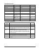
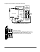
System Board Connectors
Connector Number Connector Number
IDE disk drive cable J9F1 Flexible disk drive J9F2
Keyboard J9A1 Mouse J9A1
Video J7A1 Parallel J7A1
Serial J8A1 SCSI port A J0J1
SCSI port B J0G2 Battery (Clock Module) U7D1
PCI slots P2-2, P2-1
P1-1, P1-2, P1-3
EISA/ISA slots M6, M5, M4,
M3, M2, M1
Fan J1J1, J4J3 Control panel J9H1
Power supply PS3 (J9B2)
PS4 ((J9C2
PS1-PS2 (J9O2)
Processor board slots CPU 1 - J7J1
CPU 2 - J6J1
ECC memory slots
MEM 1 - J9J1
MEM 2 - J8J1
I
2
C 1
I
2
C 2
J0J3
J0J2
Power supply on J9E1 Remote power supply J1
Hard Disk Activity J1J2, J4J2
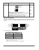
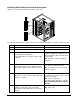
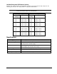
System Switches and Jumpers
Switch/
Jumper
Description Default
J9B1 Floppy Drive 1 Not used
J9C1 Floppy Drive 0 Not used
J9C3
Power Control - Disables or enables real-time clock power control.
This jumper enables power supply maintenance voltage control using
the real-time clock.
Disabled
J7D2
Boot Block (BIOS Recovery) - The flash memory contains a
protected area that cannot be corrupted. Code in this area is used to
boot the server from drive A if the BIOS gets corrupted during a BIOS
update procedure. Enable this switch to use boot block recovery, then
redo the BIOS update.
Disabled
J4H1 TDV Not used
J6A1
Video Sleep - Determines which I/O port the onboard Cirrus Logic
super VGA controller uses for its internal AT mode setup port.
REG 3C3
J7C1
Program Boot Block - lets a qualified service technician update the
boot block.
Disabled