
HP Netserver Service Handbook, Volume 2 - Mid


30
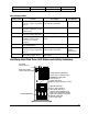
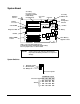
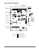
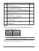
System Board Connectors, Switches, and Jumpers
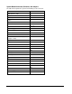
The table below explains the system board markings for all connectors.
Connector Number
IDE disk drive cable
J9
Keyboard
J1
Serial (2)
J2
Video
J3
PCI slots
J11—J14
EISA/ISA slots
J6—J7
Fans A, B
J34, J35
Power supply on A
J26
Power supply
PS1: J19 PS2: J19
PS3: J20 P4: J122 PS4: J17
Processor board slot
J18
Fast/Ultra SCSI Port A Jumper (No
jumper = Ultra)
J36
System ROM
U39
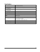
System Switches
SW1
Flexible disk drive
J15
Mouse
J1
Parallel
J3
Battery A
J30
Battery B
J31
Control panel
J28
Remote Assistant
J25
I
2
C 1
I
2
C 2
J23
J24
SCSI Port A Connector
J26
Color/Monochrome
J16
Power supply on B
J27
-3v Power Module
J21