
HP Netserver Service Handbook, Volume 2 - Mid

50
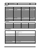
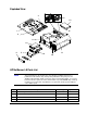
System Board Jumpers and Switches
The following table explains all connector points, sockets, and switches on the system board.
Num. Purpose Num. Purpose
J1 Keyboard J2 Mouse Connector
J3 Video Connector J4 External SCSI connector
J5 Serial A J6 Serial B
J7 Parallel J8-J12 Accessory Boards Slots
J13 Optional Battery J14 Internal SCSI Connector
J15 Power Connector J16 Flexible Disk Drive Connector
J17 Embedded AT (IDE) Controller Hard
Drive Connector
J18 Control Header (*)
J19 HD Activity Light J20-J23 Memory Sockets (SIMMs)
J24 CPU Fan Connector (**) J25 Control Panel Connection
J26 Speaker Connection
U18,
U19
SCSI Terminator U87 ZIF Microprocessor Socket
U80,
U81
Video DRAM Sockets SW1 System Board Switches
(*) make sure pins 1 and 2 are jumpered
(**) not used at this time
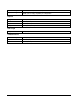
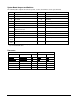
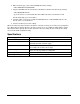
Processors
Switch Block SW1
Processor HP or Intel P/N Pin Type Switch 6 Switch 7
486/33DX D2169A (HP) DX OFF ON
OverDrive/33 D2172A (HP) 487 ON OFF
i486DX2/66 A80486DX2-66 DX OFF ON
SX OverDrive/66 ODP486SX-66 487 ON OFF
DX OverDrive/66 ODPR486DX-66 DX OFF ON
DX OverDrive/66 ODP486DX-66 487 ON OFF