
45xx Modular Disk Subsystem Manual for G-Series Releases
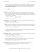
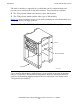
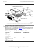
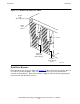
Table Of Contents
- What’s New in This Manual
- About This Manual
- 1 Introduction
- 2 Installing and Configuring the 6760 Adapter
- 3 Checking Hardware Operation
- 4 Installing and Removing CRUs
- Glossary
- Index

Introduction
45xx Modular Disk Subsystem Manual for G-Series Releases—142466
1-6
Module Sections
Module Sections
The 45xx disk module consists of two sections: the front section and the back section.
See Figure 1-2 on page 1-5.
The front section contains the disk drives and the midplane. This section is accessed
from the front of the modular storage system. Special cover plates are installed in empty
disk drive slots to keep air flow distributed evenly throughout the module.
The back section contains the back-end boards (BEBs), power supplies, and fans. This
section is accessed from the rear of the modular storage system.
Module LEDs
The front section of each 45xx disk module has two light-emitting diodes (LEDs) that
indicate hardware status for the entire module. Figure 1-3 on page 1-7 shows these
LEDs.
•
The green LED is lit when one or more BEBs are installed in the module and
powered on. This green LED can be flashed on and off using the Tandem Service
Management (TSM) FLASH command, which can help you find or identify a
particular module.
•
The amber-orange LED is not currently used, and it remains unlit.
Disk Drives
A 45xx disk module can contain up to eight disk drives. Each disk drive is a
customer-replaceable unit (CRUs). You can install any combination of 4560, 4570,
4580, or 4590 disk drives in the same module. However, for a mirrored disk volume,
both disk drives must be the same model (except when you are upgrading a disk drive to
a larger capacity: for more information about upgrading disks online, see the SCF
Reference Manual for the Storage Subsystem).
Disk Drive LEDs
Each disk drive has two indicator light-emitting diodes (LEDs), as shown in Figure 1-3
on page 1-7:
•
The green power-on LED is lit when the disk drive is powered on and ready for
access by the system. This power-on LED can be flashed on and off using the TSM
FLASH command, which can help you find a particular disk drive.
•
The amber-orange activity LED is lit when the system is polling or accessing the
disk drive.