
45xx Modular Disk Subsystem Manual for G-Series Releases
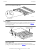
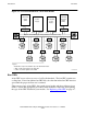
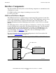
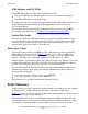
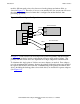
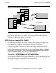
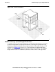
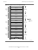
Table Of Contents
- What’s New in This Manual
- About This Manual
- 1 Introduction
- 2 Installing and Configuring the 6760 Adapter
- 3 Checking Hardware Operation
- 4 Installing and Removing CRUs
- Glossary
- Index

Introduction
45xx Modular Disk Subsystem Manual for G-Series Releases—142466
1-10
Power Supplies
ON/OFF Switch and AC Power Cord Retainer
Each power supply has an ON/OFF switch and an AC power cord retainer (see
Figure 1-5). The AC power cord retainer:
•
Holds the AC power cord in place on the power supply. After the AC power cord
has been plugged in to the power supply, the retainer slides outward to cover the
cord. With the retainer in the outward position, the power supply can be powered on
by pushing the ON/OFF switch to the ON position.
•
Prevents removal of the power supply from the module when the power supply is
powered on. Moving the retainer inward powers off the power supply.
AC Power Cord Routing
The other end of an AC power cord that is connected to a power supply is plugged
directly in to a 110 volt power source, or AC power strip in the power strip tray located
in the pedestal of the modular storage system. (AC Power strips are used for 220 volt/60
hertz and 250 volt/50 hertz power sources only. For product numbers, see Table 1-1
on
page 1-3.) Power strips are not available for 110-volt operation. The AC power strip, if
used, is plugged in to a power receptacle provided by the customer.
The tray that holds the AC power strips is located in the pedestal and is removable. A
minimum of two and a maximum of four AC power strips can be placed in the tray.
The 455DS module has one AC power cord. The fault-tolerant 455mod8 module has
two AC power cords that should be plugged in to separate AC power sources. Each AC
power source should be provided from a separate circuit protected by its own circuit
breaker. This setup provides additional fault tolerance.
Power Distribution
During normal operation, the two power supplies in a 45xx mod8 module share the load
of providing power to subsystem components, but either power supply alone can provide
all the power needed if the other power supply fails. Four buses on the midplane (two
13.8-volt buses and two 6.3-volt buses) carry power from the power supplies to
subsystem components. The fans are dual-powered by the 13.8-volt buses, one from
each power supply. The BEBs and disk drives are dual-powered by the 13.8-volt and
6.3-volt buses, one of each voltage from each power supply. Linear regulators on each
BEB and disk drive convert the power supply inputs to +5 volts for the BEB logic
circuits and the disk drives. The 455DS module is not dual-powered because it only has
one power supply. Figure 1-6
illustrates power distribution in a 45xx disk module.