
45xx Modular Disk Subsystem Manual for G-Series Releases
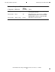
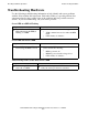
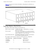
Table Of Contents
- What’s New in This Manual
- About This Manual
- 1 Introduction
- 2 Installing and Configuring the 6760 Adapter
- 3 Checking Hardware Operation
- 4 Installing and Removing CRUs
- Glossary
- Index
45xx Modular Disk Subsystem Manual for G-Series Releases—142466
3-1
3
Checking Hardware Operation
What’s in This Section
This section describes troubleshooting procedures you can use on the 45xx modular
disk subsystem.
This section includes the following topics:
•
What Component LEDs indicate on page 3-1
•
Troubleshooting Hardware on page 3-3
•
Troubleshooting With the TSM Package on page 3-4
•
Troubleshooting Fiber-Optic Cables on page 3-5
What Component LEDs indicate
Light-emitting diodes (LEDs) are indicators that provide information about the
operating status of the hardware. The LEDs help you to determine possible causes of
malfunctions. The following components of the 45xx modular disk subsystem have
indicator LEDs:
•
Module
•
Back-end board (BEB)
•
Power supply
•
Disk drive
For information about the LEDs on the 6760 ServerNet device adapter and its SACs, see
the 6760 ServerNet/DA Manual. Table 3-1
lists the LEDs for each of these components
and describes their function.
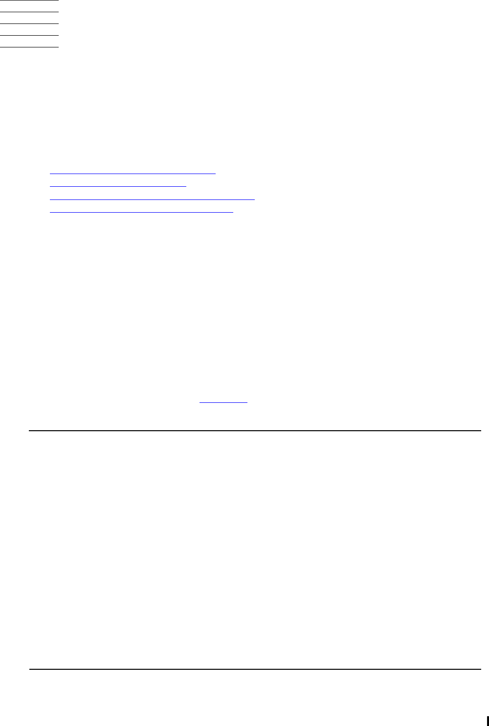
Table 3-1. Component LEDs (page 1 of 2)
Component LED Color
LED Is
Normally Notes
BEB Green Lit This LED indicates that the BEB is powered
on. You can use the TSM FLASH command
to flash this LED on and off.
BEB Amber-orange
(middle
position)
Lit This LED indicates the presence of a
fiber-optic signal and is normally lit when the
BEB is connected to a fiber-optic controller.
BEB Amber-orange
(end position)
Not lit This LED indicates error conditions.
Power
supply
Green Lit This LED indicates that the power supply is
providing power within specification limits.
Disk drive Green Lit This LED indicates that the disk drive is
powered on. You can use the TSM FLASH
command to flash this LED on and off.