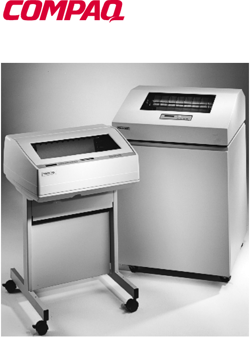
User’s Manual 5525B/31/32 Line Matrix Printer
READ THIS SOFTWARE LICENSE AGREEMENT BEFORE USING THIS PRINTER Software License Agreement Disclaimer of Warranties and Limitation of Remedies CAREFULLY READ THE FOLLOWING TERMS AND CONDITIONS BEFORE USING THIS PRINTER. USING THIS PRINTER INDICATES YOUR ACCEPTANCE OF THESE TERMS AND CONDITIONS. IF YOU DO NOT AGREE TO THESE TERMS AND CONDITIONS, PROMPTLY RETURN THE PRINTER AND ALL ACCOMPANYING HARDWARE AND WRITTEN MATERIALS TO THE PLACE YOU OBTAINED THEM, AND YOUR MONEY WILL BE REFUNDED. 1.
5525B/31/32 Line Matrix Printer User’s Manual P/N 422721-001
Compaq® makes no representations or warranties of any kind regarding this material, including, but not limited to, implied warranties of merchantability and fitness for a particular purpose. Compaq shall not be held responsible for errors contained herein or any omissions from this material or for any damages, whether direct, indirect, incidental or consequential, in connection with the furnishing, distribution, performance or use of this material.
Table of Contents 1 Introduction ............................................. 11 Printer Overview ..................................................................11 The Printer Family.........................................................11 Conventions in This Manual..........................................12 Warnings and Special Information ................................13 Related Documents.......................................................13 Graphics Enhancements...............................
Table of Contents Set the Top-of-Form ............................................................38 Procedure .....................................................................38 3 Operating the Printer............................... 41 Powering On the Printer ......................................................41 Operating Modes .................................................................41 The Control Panel................................................................42 Control Panel Keys ..
Table of Contents Menu ...........................................................................112 HOST INTERFACE ..........................................................113 Dataproducts Submenu ..............................................114 Serial Submenu...........................................................116 IEEE 1284 Parallel (Bidirectional) Submenu...............120 Ethernet Submenu ......................................................121 ETHERNET PARAMETERS .............................
Table of Contents Computer-aided Configuration with ezsetup or npconfig ..................................................................151 Configuration Through the Network with ARP ............152 Configuration Through the Network with RARP..........154 Configuration Through the Network with BOOTP .......155 Restoring Factory Defaults..........................................155 Host Configuration ......................................................156 Direct Printing Without Spooler .................
Table of Contents A Printer Specifications ........................... 207 Ribbon Specifications ........................................................207 Paper Specifications ..........................................................208 Printer Dimensions ............................................................209 Environmental Characteristics ...........................................210 Electrical Characteristics ...................................................211 Interfaces...................
Table of Contents 10
1 Introduction Printer Overview This chapter provides a general overview of your printer and the conventions used within this manual. The Printer Family The Compaq series of line matrix printers consist of 500, 1000, and 1500 lines per minute (lpm) models packaged in various configurations. All of the models offer software versatility and the latest refinements in line matrix printing technology.
Chapter 1 Printer Overview The printer combines the use of Flash, RAM, and nonvolatile RAM for program execution. The Flash is used for all program, font, and emulation storage. New fonts, emulations, or program updates can be downloaded to Flash memory via the parallel or serial interface. The RAM is used for buffers, print image storage, and execution variables. The non-volatile RAM stores configuration, statistics, and internal parameters.
Warnings and Special Information Warnings and Special Information Read and comply with all information highlighted under special headings: WARNING Conditions that can harm you as well as damage the printer. CAUTION Conditions that can damage the printer or related equipment. IMPORTANT Information that is vital to the operation of the printer. NOTE: Information affecting printer operation.
Chapter 1 Printer Overview Taking Care of Your Printer Your printer will produce high print quality jobs if it is well taken care of. Periodic cleaning, handling the printer properly, and using the correct printer supplies such as paper and ribbons ensures optimum performance. Chapter 6 explains how to clean the printer, and printer supplies are listed in Appendix A.
2 Setting Up the Printer Before You Begin Read this chapter carefully before installing and operating the printer. The printer is easy to install. However, for your safety, and to protect valuable equipment, perform all the procedures in this chapter in the order presented. Power Requirements The printer must be connected to a power outlet that supplies 88 to 135 Volts AC or 178 to 270 Volts AC at 47 to 63 Hz. The printer automatically senses and adjusts itself to conform to the correct voltage range.
Chapter 2 Select a Site Select a Site Select a printer site that meets all of the following requirements: • • Permits complete opening of the printer cover and doors. • Has a standard power outlet that supplies 88-135 Volts AC or 178270 Volts AC power, at 47 to 63 Hz. • • Is relatively dust-free. • For cabinet models, allows at least three feet of clearance behind the printer. (This permits air to circulate freely around the printer and provides access to the paper stacking area.
Printer Dimensions 57.5 in. (146.1 cm) 41.0 in. (104 cm) 27.0 in. (68.6 cm) 29.0 in. 83.0 in. (73.7 cm) (210.8cm) 27.0 in. 27.0 in. (68.6 cm) (68.6 cm) Figure 1. Printer Dimensions (Cabinet Model) m) 25 in. (63.5 cm.) 10.5 in. (26.67 cm.) 48.0 in. (122 cm.) 24.6 in. (62.48 cm.) 30 in. (76.2 cm.) Figure 2.
Chapter 2 Printer Component Locations Printer Component Locations Familiarize yourself with the names and locations of the printer components, shown in Figure 3, before continuing with the rest of the installation procedure. 2 4 3 5 6 7 8 9 1 10 11 13 12 Figure 3.
Legend: 1) 2) 3) 4) 5) 6) 7) 8) 9) 10) 11) 12) 13) Hub Latch Ribbon Spool Horizontal Adjustment Knob Tractor Lock Paper Scale Splined Shaft Paper Support Tractor Hammer Bank Cover and Ribbon Mask Vertical Position Knob Forms Thickness Lever Ribbon Guide Ribbon Loading Path Diagram Remove Packing Materials CAUTION To avoid shipping damage, reinstall the shipping restraints whenever you move or ship the printer.
Chapter 2 Remove Packing Materials 3 1 2 1. Raise the printer cover. 2. Remove the cardboard packing (1). 3. Open the tractor doors. Push the tractor locks down. Slide the tractors outward as far as they will go. The forms thickness lever (2) should be in the fully open (raised) position. 4. Remove the envelope (3) containing the sample configuration printout. Store the envelope in the pouch attached to the left interior side of the cabinet.
6 5 4 7 5. Slide the paper supports (4) outward as far as they will go. Lift the hammer bank protective foam (5) and remove it from between the ribbon mask and the platen. 6. Remove the foam strips (6) and the tape securing the foam strips. 7. Rotate the forms thickness lever (7) downward to position “A”.
Chapter 2 Remove Packing Materials 8 8. Rotate the platen protective foam (8) toward the front of the printer and out from under the support shaft. Adjust the Paper Supports 2 1 2 1. Slide the paper supports (1) inward until they are approximately four inches from the tractor doors (2).
Release the Paper Chains (Cabinet Model) Release the Paper Chains (Cabinet Model) 1 2 1 3 1. Open the cabinet rear door. 2. Cut the tie wraps (1) and release the paper chains (2) from the bags (3) at the top rear of the printer frame. Remove the tie wraps and bags. 3. Make sure each chain hangs freely, with no kinks or knots.
Chapter 2 Remove Packing Materials Remove Tags Cabinet Model 3 1 2 1 2 3 Figure 4. Removing Tags (Left: 1000/1500 lpm models; Right: 500 lpm models) 1. Remove the tie wrap (1) attached to the passive stacker paper fence (3). It is marked with a large, red tag (2). 2. Close the cabinet rear door.
Remove Tags Pedestal Model 3 1 2 Remove the tie wrap (1) attached to the output basket (3). It is marked with a large, red tag (2).
Chapter 2 Remove Packing Materials Attach the Output Basket (Pedestal Model) $ $ 1. Place the output basket in the holes in the back of the printer. 2. Screw the ground wire attached to the output basket to the printer.
Cabinet Model Connect the Interface and Power Cords Before you connect the interface and power cables, verify the voltage source at the printer site conforms to the requirements specified in “Power Requirements” on page 15. Cabinet Model 1 2 5 4 3 Legend: 1) 2) 3) 4) 5) Host Interface Connectors I/O Cover Cable-Routing Notches AC Power Cable AC Power Connection Figure 5.
Chapter 2 Connect the Interface and Power Cords 1. Make sure the printer power switch is set to O (Off). 2. Open the cabinet rear door, and remove the cover from the selected I/O connector. (See “Interface Connections” on page 30.) 3. Locate the cable routing notch in the lower left corner of the back of the cabinet (see Figure 5). 4. Hold the I/O cable below its connector and gently push the cable through the opening in the grommet seated in the notch. 5.
Pedestal Model 8. Guide the power cord up through the hole in the lower right back corner of the cabinet (see Figure 5). Thread the power cord inside the bracket where the gas spring is attached. 9. Plug the power cord into the printer AC power connector, then into the AC power outlet. Pedestal Model 4 1 2 5 3 Legend: 1) 2) 3) 4) 5) Parallel Connector Auxiliary I/O Serial Connector Power Switch AC Power Connector 1. Make sure the printer power switch is set to O (OFF). 2.
Chapter 2 Connect the Interface and Power Cords Interface Connections 1 5 2 3 2 3 1 4 4 Legend: 1) 2) 3) 4) 5) Parallel (not present on Network-based models) Auxiliary I/O Diagnostic Serial RS-232/RS-422 Dataproducts Standard Adapter Figure 6. Standard Interfaces (Left: Pedestal Model; Right: Cabinet Model) 1 2 3 Legend: 1) 2) 3) Network 10Base2 Network 10Base-T Dataproducts Long Line Figure 7. Optional Interfaces for the Auxiliary I/O 1.
Attach the Control Panel Overlays Install Basic Components The following procedures describe how to attach the printed overlays to the control panel and install the printer ribbon and paper. Attach the Control Panel Overlays 1. Choose the overlay labels in the appropriate language. 2. Cabinet Models: Open the printer cover, peel off the protective backing, and press the overlay into place. 3.
Chapter 2 Install Basic Components Load the Ribbon 1. Refer to the ribbon path diagram molded onto the shuttle cover (see “Printer Component Locations” on page 18). 2. Open the printer cover. 2 1 3. Raise the forms thickness lever (1) as far as it will go. 4. Open the tractor doors (2). 3 5. Squeeze the right hub latch (3) and place the full spool on the right hub. Be sure the ribbon feeds off the outside of the spool. Press the spool down until the hub latch snaps into place.
Load the Ribbon 4 6. Thread the ribbon around the ribbon guide (4) and along the ribbon path. Be sure to thread the ribbon between the hammer bank cover and the ribbon mask. 7. Place the empty spool on the left hub. Press the spool down until the hub latch snaps into place. Turn the empty spool by hand to make sure the ribbon tracks correctly in the ribbon path and ribbon guides.
Chapter 2 Install Basic Components Load the Paper When you start this procedure, verify that the printer cover is open, the forms thickness lever is raised, and the tractor doors are open. (See “Printer Component Locations” on page 18). 1 2 Legend: 1) 2) Edge Of Paper Box 1. For cabinet models, align the paper supply with the label on the floor. Make sure that the paper pulls freely from the box. 3 3 2. Feed the paper up through the paper slot (3).
Load the Paper 5 4 6 3. Pull the paper (4) above and behind the ribbon mask, which is a silver metal strip with a clear plastic edge protector. Load the paper on the left tractor sprockets and close the tractor door (5). CAUTION To avoid damage to the printer caused by printing on the platen, always position the left tractor unit directly to the left of the “1” mark on the paper scale. 4. If adjustment is necessary, unlock (6) the left tractor.
Chapter 2 Install Basic Components 8 9 10 6. Make sure the leading edge of the first sheet of paper is parallel to the tractor splined shaft (8). If the paper is misaligned, reload it onto the tractor sprockets until its edge is parallel to the splined shaft. 7. Slide the right tractor to remove paper slack or to adjust for various paper widths. Lock the tractor. 8. After both tractors are secured, you may use the horizontal adjustment knob (9) to make fine horizontal paper adjustments.
Load the Paper A B C 9. Lower the forms thickness lever. Set it to match the paper thickness. (The A-B-C scale corresponds approximately to 1-, 3-, and 6-part paper thickness.) NOTE: Do not set the forms thickness lever too tightly; excessive friction can cause paper jams, ribbon jams with potential for ribbon damage, smeared ink, or wavy print.
Chapter 2 Set the Top-of-Form Set the Top-of-Form When paper is loaded into the printer, it must be told where you want the top of your form to be. This procedure must be performed the first time paper is introduced into the printer, as well as every time new paper is loaded. Procedure 1. Be sure the forms thickness lever is lowered. If the printer is off, set the power switch to I (On). 2. Press ON LINE to place the printer in offline mode. The LCD will then display “OFFLINE / CONFIG. CONTROL.” 3.
Procedure 3 4 5 5. Locate the TOF indicator (3). It is the small tab located on both the right and left tractor door. 6. Turn the vertical position knob (5) to align the top of the first print line with the TOF indicator. For best print quality, it is recommended the top-of-form be set at least 1/2 inch below the perforation (4).
Chapter 2 Set the Top-of-Form A B C 7. Lower the forms thickness lever. Set it to match the paper thickness. (The A-B-C scale corresponds approximately to 1-, 3-, and 6-part paper thickness.) NOTE: Do not set the forms thickness lever too tightly; excessive friction can cause paper jams, ribbon jams with potential for ribbon damage, smeared ink, or wavy print. 8. Press SET TOF. The top-of-form position you have set moves down to the print position. 9.
3 Operating the Printer Powering On the Printer When you power on the printer, it executes a self-test. The default power-up state is online. When the self-test completes and the software has initialized successfully, the status indicator light turns on, indicating the printer is online. The default value of the type of emulation you have installed appears in the display.
Chapter 3 The Control Panel The current operating mode may be selected via control panel keys, or may result from routine operations such as powering on the printer. The Control Panel Figure 9 and Figure 10 show the keys, displays and indicators as they appear on the control panel. The following section provides descriptions of each of the control panel keys and their functions. Key combinations are indicated with the plus (+) sign.
Control Panel Keys Legend: 1) 2) 3) 4) 5) 6) 7) 8) 9) 10) Message Display Status Indicator CLEAR SHIFT SET TOF / L.P.I. ADJ. ENTER / PAGE L. ADJ. ON LINE FF LF VIEW Control Panel Keys ON LINE Toggles the printer between online and offline modes. If a fault condition exists, pressing this key will clear the fault message and return the printer from fault mode to offline mode.
Chapter 3 The Control Panel VIEW In offline or online mode, allows you to view and adjust the placement of data on the page, or to remove peel-off labels. With the printer online or offline, press and release to move paper forward for inspection. The last data printed advances to the tractor area. Press VIEW a second time to move the paper back to its previous print position. If the printer is online and printing, press VIEW to stop printing. The paper advances.
Control Panel Keys SHIFT The printer must be offline to perform the following functions: • • Press SHIFT+CLEAR to reset the PCL-II emulation. • Press SHIFT+Page L. Adj to access the form length menu in lines or inches. The page length is selected by lines/page or inches/ page, depending on which option is chosen in the PCL-II submenu. • Press SHIFT+= to micro step the paper upward in 1/72 inch increments. • Press SHIFT+> to micro step the paper downward in 1/72 inch increments. Press SHIFT+L.P.I.
Chapter 3 The Control Panel UP or DOWN ( = or > ) Moves up and down between levels in the configuration menus and makes vertical forms adjustment. After pressing VIEW, press = or > to adjust the paper up or down in 1/72 inch increments for fine vertical forms alignment. After pressing ON LINE, press = or > to move through levels in the configuration menus. UP + DOWN ( = + > ) Locks and unlocks the ENTER key. PREV or NEXT ( ; or < ) Moves between the options on the current level of configuration menu.
Reloading Paper Operational Procedures This section outlines certain basic procedures which need to be performed when necessary in order to keep your printer operating. Reloading Paper Follow this procedure when “LOAD PAPER” displays. (This message occurs when the last sheet of paper passes through the paper slot.) This procedure reloads paper without removing the last sheet of the old paper supply. This action retains the current top of form setting. 1. Raise the printer cover.
Chapter 3 Operational Procedures 4. Locate the paper slot and feed the paper up through it (see Figure 11). It may be easier to feed one corner of the new paper up through the slot first. When this corner can be grasped from the top, rotate the paper back to the normal position. NOTE: If you are using thick, multi-part forms and are unable to load the new paper over the existing paper, go to step 14. 5. Hold the paper to prevent it from slipping down and through the paper slot. 3 4 6 5 6.
Reloading Paper A B C 9. Lower the forms thickness lever. Set it to match the paper thickness. (The A-B-C scale corresponds approximately to 1-, 3-, and 6-part paper thickness.) NOTE: Do not set the forms thickness lever too tightly; excessive friction can cause paper jams, ribbon jams with potential for ribbon damage, smeared ink, or wavy print. 10. Press CLEAR to remove the “LOAD PAPER” fault message from the display. 11.
Chapter 3 Operational Procedures Perform steps 14 through 30 only if you are unable to load the new paper over the existing paper in step 4. 14. Open both tractor doors. 15. Remove the paper from the tractors. Allow the paper to fall into the paper supply area. 7 7 16. Feed the paper up through the paper slot (7). Hold the paper to prevent it from slipping down through the paper slot.
Reloading Paper 9 8 17. Pull the paper (8) above and behind the ribbon mask. (The ribbon mask location is shown on the ribbon path diagram.) 18. Load the paper on the left tractor and close the tractor door (9). CAUTION To avoid damage to the printer caused by printing on the platen, always position the left tractor unit directly to the left of the “1” mark on the paper scale. 19. Normally, you should not need to adjust the position of the left tractor.
Chapter 3 Operational Procedures 10 20. Move the paper supports (10) as necessary to support the paper between the tractors. 11 12 21. Unlock the right tractor (11). Load the paper onto the sprockets and close the tractor door (12). If necessary, slide the right tractor to remove paper slack or to adjust for various paper widths. Then, lock the tractor. 13 22. After both tractors are secured, you may use the horizontal adjustment knob (13) to make fine horizontal paper adjustments.
Reloading Paper 14 14 23. On pedestal models: Using the vertical position knob to move the paper up, guide the paper over the lower paper guide (14) and through the slot in the top cover. Close the platen and the printer cover. 24. Press FF several times to make sure the paper feeds properly beyond the tractors and over the lower paper guide (14). Feed sufficient paper to ensure the paper stacks correctly. 25. On cabinet models: Open the cabinet rear door.
Chapter 3 Operational Procedures 15 17 16 26. Locate the TOF indicator (15). It is the small tab located on both the right and left tractor door. 27. Turn the vertical position knob (16) to align the top of the first print line with the TOF indicator. For best print quality, it is recommended the top-of-form be set at least 1/2 inch below the perforation (17). A B C 28. Lower the forms thickness lever. Set it to match the paper thickness.
Unloading Paper 30. Press SET TOF. The top-of-form you have set moves down to the print position. If there are data in the buffer, the paper moves forward to the last print position on the next page. 31. Press ONLINE and close the printer cover. Unloading Paper 1. Press ON LINE to place the printer in offline mode, and open the printer cover. 2. For cabinet models, open the cabinet rear door. 3. Tear off the paper at the perforation. 4.
Chapter 3 Operational Procedures 2 1 7. To completely remove the paper from the printer: a. Raise the forms thickness lever (1) as far as it will go, and open both tractor doors (2). CAUTION Be careful when pulling any paper backward through the paper path, especially when using a label stock. If you are not careful, labels can detach and adhere to the printer within the paper path, where only an authorized service representative can remove them. b. Remove the paper from the tractors.
Replacing the Ribbon Replacing the Ribbon 1. Press ON LINE to place the printer in offline mode. 2. Open the printer cover. 2 1 3. Remove the old ribbon: a. Raise the forms thickness lever (1) as far as it will go. b. Press in on the hub latches (2) and lift the ribbon spools off the hubs. Lift the ribbon out of the ribbon path. 4. Discard the old ribbon. 5. If necessary, clean the interior of the printer. (See “Cleaning Requirements” on page 195.
Chapter 3 Operational Procedures 6. Install the new ribbon: a. With the ribbon to the outside, place the full spool on the right hub (3). Press down on the spool until the hub latch snaps in place. 3 4 b. Thread the ribbon around the ribbon guide (4) and along the ribbon path. (Refer to the ribbon path diagram on the shuttle cover.) Be sure to thread the ribbon between the hammer bank cover and the ribbon mask. CAUTION The ribbon must not be twisted.
Replacing the Ribbon A B C 7. Lower the forms thickness lever. Set it to match the paper thickness. (The A-B-C scale corresponds approximately to 1-, 3-, and 6-part paper thickness.) NOTE: Do not set the forms thickness lever too tightly; excessive friction can cause paper jams, ribbon jams with potential for ribbon damage, smeared ink, or wavy print. 8. Close the printer cover. 9. Press ON LINE to return the printer to online mode.
Chapter 3 Operational Procedures Canceling a Print Job The procedure to cancel a print job depends on the printer emulation and your application software. Contact your System Administrator for additional information. 1. If the printer is online, press ON LINE to place the printer in offline mode. 2. From the host system, stop the print job.
4 The Configuration Menus Configuration Overview In order to print data, the printer must respond correctly to signals and commands received from the host computer. Configuration is the process of matching the printer’s operating characteristics to those of the host computer and to specific tasks, such as printing labels, or printing on different sizes of paper.
Chapter 4 Configuration Overview Changing and Saving Parameter Settings You may change a printer parameter setting, such as line spacing or forms length, either by pressing keys on the control panel to configure the printer’s resident set of configuration menus, or by sending emulation control codes from a host attached to the printer (the host data stream). An example procedure for using the control panel to change parameter settings begins on page 64.
Navigating the Menus Navigating the Menus To manipulate configurations it is important to understand how to navigate through the menus. Review the following instructions before you begin making changes to the printer. You must be offline to move within the menus. ON LINE OR OR ENTER + Press to toggle between online and offline modes. Press to move up or down through the menu levels. Press to scroll through the available choices on a chosen level. Press to confirm selection.
Chapter 4 Configuration Overview Changing Parameters Example * = Factory Default OFFLINE CONFIG. CONTROL ... PRINTER CONTROL Unidirectional Disable* Enable PMD Fault Enable* Disable Slow Paper Slew Disable* Enable Power Saver Time 15 min.* (15-60 min.) A configuration consists of several parameters. The default factory configuration has a starting set of parameters.
Changing Parameters Example Step 1. 2. Press LCD Notes Make sure the printer is on. Raise the printer cover. ON LINE 3. + OFFLINE CONFIG. CONTROL ENTER SWITCH UNLOCKED Allows you to make configuration changes. OFFLINE CONFIG. CONTROL 4. UNTIL OFFLINE PRINTER CONTROL 5. PRINTER CONTROL Unidirectional 6. Unidirectional Disable* 7. OR 8. ENTER 9. Unidirectional Enable Cycle through the choices. Unidirectional Enable* The * indicates this choice is active.
Chapter 4 Step 13. Configuration Overview Press ENTER 14. + 15. ON LINE LCD Notes Slow Paper Slew Enable* The * indicates this choice is active. ENTER SWITCH LOCKED Locks the ENTER key. ONLINE LinePrinter+ Places the printer in online mode. 16. Close the printer cover. The printer is ready for operation. The parameters you have changed remain active as long as the printer is on. When you turn off the printer, the parameters are erased from memory unless you save them in a configuration.
Saving Your New Configuration Once you have saved a custom configuration using this option, it is not lost if you power off the printer. You can load a configuration for a specific print job (see “Load Config.” on page 71). You can also modify and resave it. You may want to print your configurations (see “Print Config.” on page 72) and store them in a safe place, such as inside the printer cabinet. If the Protect Configs.
Chapter 4 Step 8. NOTE: Configuration Overview Press ENTER The * indicates this choice is active. CONFIG. CONTROL Save Config. 10. UNTIL 11. CONFIG. CONTROL Print Config. Print Config. Current 12. OR ENTER 14. + 15. Save Config. 2* Notes It is recommended you print the configuration. To print the configuration go to Step 9. To skip this procedure and resume printer operation, go to Step 14. 9. 13. LCD ON LINE Print Config. 2 Press until the desired parameter displays. OFFLINE CONFIG.
Main Menu Main Menu 1 If installed OFFLINE CONFIG. CONTROL page 71 Load Config. Save Config. Print Config. Delete Config. Power-up Config. Protect Configs.
Chapter 4 Configuration Overview Brief descriptions follow for the first-level configuration menu options: 70 • CONFIG. CONTROL — These options allow you to save, print, load, delete, name, and protect entire sets of configuration parameters, as well as select the default power-up configuration. • ACTIVE EMULATION — This menu allows you to select the active emulation: PCL-II or LinePrinter+. The optional IGP/PGL or IGP/VGL emulations can be selected if they are installed.
Menu CONFIG. CONTROL The CONFIG. CONTROL menu allows you to control your printer’s configurations according to the specifications necessary for your print jobs. Menu * = Factory Default CONFIG. CONTROL (from page 69) Load Config. Factory* 1-8 Save Config. 1* (1-8) Print Config. Current* Factory Power-up All 1-8 Delete Config. 1* (1-8) Power-up Config. Factory* 1-8 Protect Configs. Disable* Enable Load Config. The printer can store numerous configurations in memory.
Chapter 4 CONFIG. CONTROL Save Config. This option allows you to save up to eight unique configurations to meet different print job requirements. This eliminates the need to change the parameter settings for each new job. The configurations are stored in memory, and will not be lost if you turn off the printer. If the Protect Configs. parameter is enabled, the new configuration will not be saved unless the existing configuration has been deleted first. The factory default configuration cannot be changed.
Menu ACTIVE EMULATION * = Factory Default Emulation 1Optional ACTIVE EMULATION (from page 69) PCL-II* LP PLUS IGP/PGL1 IGP/VGL1 The ACTIVE EMULATION function allows you to activate either the PCL-II or LinePrinter Plus emulation, as well as the optional IGP/PGL or IGP/VGL emulations, if they are installed. There are two methods for selecting the desired emulation. The first is by selecting the emulation directly from the printer menu.
Chapter 4 EMULATION EMULATION The EMULATION menu is the gateway to configure the emulations available with your printer. The control codes for each of these emulations are described in their respective Programmer’s Reference Manuals. * = Factory Default Emulation 1Optional EMULATION (from page 69) PCL-II* LP PLUS IGP/PGL1 IGP/VGL1 page 75 page 79 page 93 page 101 PCL-II Emulation Hewlett-Packard’s Printer Control Language that is compatible with Compaq systems.
PCL-II Emulation PCL-II Emulation * = Factory Default EMULATION (from page 74) PCL-II Primary Char Set Secondary Char Set Page Length Rep. ID ID Inches/Page* 0* - 109, xx 0* - 109, xx Lines/Page Symbol Set Symbol Set (see next page) (see next page) Pitch Pitch 10*, 12, 13.3 10*, 12, 13.3 15, 16.67, 20 15, 16.67, 20 Density Density Data Proc.* Data Proc.
Chapter 4 EMULATION Primary Char Set (from page 75) Secondary Char Set (from page 75) Symbol Set Symbol Set Roman-8(8U)* Turkish-8(8T) Arabic-8(8V) Cyrillic(8R) Japan Postnet Katakana Post ASCII(OU) Math Sym(0A/0M) LineDraw(0B/0L) IS0 Den/Nor(0D) Roman Ext.
PCL-II Emulation Page Length Representation • Inches/Page. All page length calculations are based on the inches displayed on the panel. • Lines/Page. All page length calculations are based on the number of lines per page displayed on the panel. For example, if the form in use is 82 lines at 6 lpi, the page is physically 13.67 inches. Since 13.67 inches is not selectable from the Length in Inches menu, change the representation to lines, then set the number of lines to 82.
Chapter 4 EMULATION PTX Linefeed • Disable. The default. Linefeed is performed as calculated from the bottom of the graphics or barcode, thereby disrupting the vertical text alignment. • Enable. The Linefeed moves to the next line as calculated from the Top of Form position, thereby retaining vertical text alignment. When printing graphics or bar codes, you may want to set the PTX Linefeed parameter to Enable to maintain text alignment.
LinePrinter Plus Emulation LinePrinter Plus Emulation * = Factory Default EMULATION (from page 74) LinePrinter+ Printer Protocol Print Char. Set P-Series (see page 83) Proprinter XL (see page 87) Epson FX (see page 90) CPI/LPI Select Font Attributes Select CPI 10.0 CPI* 12.0 CPI 13.3 CPI 15.0 CPI 17.1 CPI 20.0 CPI Select LPI 6.0 LPI* 8.0 LPI 10.3 LPI (see below) Page Format (see next page) Font Attributes (from above) Typeface Prop. Spacing Data Process.
Chapter 4 EMULATION * = Factory Default Page Format (from page 79) Margins Perforation Skip Left Margin 0* columns (0-369) Right Margin 0* columns (0-369) Bottom Margin 0* lines (0-451) Disable* 1/2 inch 2/3 inch 5/6 inch 1 inch Form Length Form Width Abs. Width IN Abs. Length IN 13.6* inches 11.0* inches (0.1-13.6) (0.1-24) Abs. Width MM Abs. Length MM 345.4* millimeters 279.4* millimeters (0.1-345.4) (0.1-609.6) Funct. of CPI Funct.
LinePrinter Plus Emulation • OCR-A / OCR-B. Optical character recognition fonts printing at 120 dpi horizontally and 144 dpi vertically. Both fonts print only at 10 cpi. • High Speed. A draft quality font printing at 120 dpi horizontally and 48 dpi vertically. The width of the font varies with the cpi. • NLQ Sans Serif. A high quality font printing at 180 dpi horizontally and 96 dpi vertically. This font prints without serifs. The width of the font varies with the cpi.
Chapter 4 EMULATION Slashed Zero This parameter allows you to print the numeral “0” with or without the slash. This option applies to all character sets except OCR-A and OCR-B. • • Disable. Zero is printed without a slash. Enable. Zero is printed with a slash. Page Format Margins • Left Margin. Set in columns. Column zero is defined as the far left edge of the page, and column numbering increments from left to right. • Right Margin. Set in columns.
P-Series Emulation P-Series Emulation * = Factory Default Printer Protocol (from page 79) P-Series Control Code 06 6.0 LPI 8.0 LPI* 10.3 LPI Select SFCC 1* (hex 00-7F) Control Code 08 Elongated* Backspace EVFU Select Enable* Disable IBM PC* Define CR Code CR = CR* CR = CR + LF Disable* Enable Alt.
Chapter 4 EMULATION Control Code 06 Control Code 06 defines the function of ASCII code hex 06 (ACK). You can select an alternate line spacing of 6, 8 or 10.3 LPI. Control Code 08 Control Code 08 defines the function of ASCII code hex 08 (BS). You can define the code to output an elongated character or a backspace. Define CR Code This option controls the action of the printer when it receives a Carriage Return code (hex 0D) from the host computer.
P-Series Emulation Overstrike • Enable. Common dots appear darker in characters printed over each other, as shown below. The print position moves one-half dot to the right. Overstrike printing occurs at a decreased speed. • Disable. If you are using a control code for overstrike, but it is disabled in the printer control panel, no bolding will occur. Define LF Code • LF = CR + LF. Forces an automatic carriage return with each line feed command.
Chapter 4 EMULATION EVFU Select Controls how the printer handles vertical formatting. • Enable. Enables the VFU and selects P-Series compatible Electronic Vertical Format Unit (EVFU). • Disable. Disables all VFU processing. Alt. Set 80-9F Determines whether the printer processes ASCII codes hex 80 through hex 9F as control codes or as printable characters. Character Set Specifies a character set. To use one of these sets, choose the desired set and press ENTER.
Proprinter XL Emulation Proprinter XL Emulation * = Factory Default Printer Protocol (from page 79) Proprinter XL Define CR Code CR = CR* CR = CR + LF Auto LF Enable* Disable Define LF Code LF = LF* LF = CR + LF FF Valid at TOF Enable* Disable Character Set Alt.
Chapter 4 EMULATION Auto LF This option defines the printer actions when print data is received past the forms width setting. • Enable. Performs an automatic carriage return and line feed when data is received past the forms width. • Disable. Discards any data past the forms width. Define LF Code • LF = LF. Does not perform an automatic carriage return when a line feed command is received. The next print position will be the current print position of the next line. • LF = CR + LF.
Proprinter XL Emulation Alternate Char Set This option determines if data in the range of hex 80 through hex 9F should be interpreted as a control code or as a printable character. • Set 1. Interprets data in the range of hex 80 through hex 9F as a control code. • Set 2. Prints data for the characters at hex locations 03, 04, 05, 06, 15 and 80 through 9F. 20 CPI Condensed Compressed print characters are narrower than the normal character set.
Chapter 4 EMULATION Epson FX Emulation * = Factory Default Printer Protocol (from page 79) Epson FX Define CR Code CR = CR* CR = CR + LF Alt.
Epson FX Emulation Define CR Code The Define CR Code option controls the action of the printer when it receives a Carriage Return code (hex 0D) from the host computer. If this feature is enabled, each time the printer receives a Carriage Return, it inserts an additional Line Feed code (hex 0A) into the data stream. Do not use this feature if the host computer sends Line Feeds to the printer. • CR = CR. Does not insert an extra Line Feed after each Carriage Return. • CR = CR + LF.
Chapter 4 EMULATION Character Set Specifies a character set. To use one of these sets, choose the desired character set and press ENTER. Note that when OCR-A or OCR-B is selected as the print language, the Font Attribute Typeface option under the LinePrinter Plus menu (page 80) is changed to OCR-A or OCR-B, respectively. 20 CPI Condensed Compressed print characters are narrower than the normal character set.
IGP/PGL Submenu IGP/PGL Submenu The IGP/PGL emulation is the software based Intelligent Graphics Processor (IGP). It is based upon, and is compatible with, the Printronix IGP-100/200/400 board using the Printronix Graphics Language (PGL). The IGP/PGL graphics processing features are detailed below. Features On-Line Form and Label Generation makes it easy to create forms or labels with a “preprinted” look for each application.
Chapter 4 EMULATION Rotated Alphanumerics permit new concepts in form design. Normal, expanded, and compressed character strings can be rotated 90 degrees clockwise or counterclockwise, or they can be printed upside down. Reversed Print permits highlighting and contrasting by printing white characters on a dark background. Automatic Increment/Decrement Capability allows batch form processing.
IGP/PGL Submenu * = Factory Default EMULATION (from page 69) IGP/PGL Define CR Code CR = CR* CR = CR + LF Select Font 0-32 UPC Descenders Enable* Disable Define LF Code LF = LF* LF = CR + LF Select LPI 6* 8, 9, 10 Compressed CPI Disable* Enable Autowrap Disable* Enable Auto Uppercase Disable* Enable Ignore Char Ignore Mode Disable* Enable Select Char 0* (0-255) Select SFCC 126* (1-255) Skip Cmd Prefix Enable* Disable IGP100 Compatbl.
Chapter 4 EMULATION Define CR Code (Carriage Return) This parameter forces the printer to insert an automatic Line Feed code into the data stream whenever a Carriage Return code occurs. This is to be used only if the host computer does not send Line Feeds to the printer. • CR = CR. Does not perform a line feed. The next print position will be print position 1 of the current line. • CR = CR + LF. Performs an automatic line feed. The next print position will be print position 1 of the next line.
IGP/PGL Submenu PI Slew Range You can specify how many lines the paper will feed. • 15. A paper slew of 1-15 will move 1-15 lines. A paper slew of 0 will move 1 line. • 16. A paper slew of 0-15 will move 1-16 lines. CR Edit This parameter determines if a carriage return will be followed by a line feed. • Disable. The printer ignores all carriage returns that are not followed by line feeds. • Enable. The printer processes all carriage returns, even for those that are not followed by line feeds.
Chapter 4 EMULATION Select LPI This is the number of lines to be printed per inch. For example, at 6 lpi there is 1/6 inch from the top of one print line to the top of the next print line. Auto Uppercase This parameter enables the printer to print text in all uppercase when using the ALPHA command. • • Disable. The printer will print text in upper and lowercase. Enable. The printer will print text in uppercase only.
IGP/PGL Submenu Extended Execute Copy • Disable. Dynamic data, overlay data, etc. are not allowed if the optional Form Count parameter (number of forms to print) is specified as part of the Execute command. (This setting is IGP-100 compatible.) • Enable. Dynamic data, overlay data, etc. are allowed within a form in which the Form Count parameter is specified in the Execute command. In this case, the exact same form (with identical dynamic data, etc.) is printed for whatever the Form Count is.
Chapter 4 EMULATION Select Character Instructs the IGP/PGL which decimal character (0-255) to ignore from the host. IGP100 Compatbl. This option instructs the IGP/PGL to behave similar to the IGP-100 with respect to certain commands. All new users with new applications should select the “Disable” option. Selecting this mode insures the printer behaves as described in this manual. • • Disable. The IGP/PGL does not emulate the IGP-100 mode. Enable. The IGP/PGL emulates the IGP-100 version.
IGP/VGL Emulation IGP/VGL Emulation Code V Graphics language (VGL) is an Intelligent Graphics Printing (IGP) software emulation designed for your line matrix printer. The IGP Code V emulation of the QMS Code V Version II programming language produces on-line forms, bar codes, and alphanumeric textgeneration. The graphics processing features are detailed below. Features On-Line Form and Label Generation makes it easy to create forms or labels with the “preprinted” look for each application.
Chapter 4 EMULATION Logos are easily created using alphanumeric commands and a variety of print and shading features, providing a “customized” appearance for forms, reports, and labels. The registered trademark, copyright, TUV ®, GS-Mark, UL®, and CSA® symbols are provided as standard designs on the Code V, and you can also define custom symbols. Reverse and Shaded Print permit highlighting and contrasting by printing white characters on a dark background or white characters on a gray, shaded background.
IGP/VGL Emulation * = Factory Default EMULATION (from page 69) CODE V SFCC & Pwrup LPI Control Character 6* 94* (17-255) 7, 8, 9, 10 Ignore Mode Disable*/Enable Free Format Disable*/Enable Mgnum Conversion Disable*/Enable ISO Char Set 0-32 Graphics Options (see next page) Error Handling Ignore/DB8 Setup Ignore Nulls Error Msgs Disable*/Enable Enable*/Disable Data Bit 8 Error Markers Enable*/Disable Enable*/Disable Offpage Errors Disable*/Enable Barcode Errors Enable*/Disable PI Control Printer
Chapter 4 EMULATION Graphics Options (from page 103) Slashes in Zeros Enable* Disable UPC Descenders Disable* Enable Ignore Dots Append Rotated Disable* Enable Disable* Enable Rot. Char Size Ignore Spaces Adjusted* Not Adjusted Disable* Enable Truncate Alpha True Vert 1/10 Enable* Disable Disable* Enable Midline PY Disable* Enable Convert to U/C Disable* Enable Absorb After ^PY Absorb All* Absorb Motion Disable Absorb After ^PN Disable* Enable IGP 110 Compatbl.
IGP/VGL Emulation Ignore Mode • • Disable. The default. Enable. Selects the ignore mode as the power-up default, and selects the graphics mode ^PY as the power-up default. All characters are ignored until a ^A command is received. Free Format • • Disable. The default. Enable. Selects free format mode as the power-up default, and selects the graphics mode ^PY as the power-up default. Free format causes the Code V to ignore carriage returns, line feeds and all characters below hex 20 sent from the host.
Chapter 4 EMULATION Ignore Dots • • Disable. The default. Enable. Causes the Code V to expect position values to be specified in only 1/10ths of an inch. If the dot position is also given, it is treated as text. Append Rotated • Disable. Logos and alphanumeric strings are treated as separate elements. • Enable. Appends logos to an alphanumeric string rotated in a clockwise, counterclockwise, or inverted orientation.
IGP/VGL Emulation UPC Descenders • Disable. UPC/EAN bar codes are printed without descenders if there is no human readable data. • Enable. UPC/EAN bar codes are printed with descenders, even if there is no human readable data. Rot. Char Size • Adjusted. Rotated (clockwise/counterclockwise), expanded characters have a different size than an unrotated character with the same size parameters. • Not Adjusted.
Chapter 4 EMULATION Absorb After ^PN • Disable. All line terminators that immediately follow the ^PN command are sent to the printer and processed. • Enable. All line terminators that immediately follow the ^PN command are ignored. IGP 110 Compatbl. This option instructs the Code V to behave similar to the IGP-110 with respect to certain commands. All new users with new applications should select the “Disable” option. Selecting this mode insures the printer will behave as described in this manual.
IGP/VGL Emulation Offpage Errors • Disable. Does not report errors for elements that start or end beyond the right edge of the page. • Enable. Reports errors for elements that start or end beyond the right edge of the page. Barcode Errors • Enable. An error message will print when invalid bar code data is encountered. • Disable. Code V will not print an error for illegal bar code data; the bar code will be skipped.
Chapter 4 EMULATION NOTE: Data bit 8 is interpreted as either data bit 8 or PI signal, but never both. When enabled as data bit 8, data bit 8 has priority over the PI signal, and all data above hex 7F is used to access character data and not to interpret PI line data. Conversely, when data bit 8 is disabled and the PI signal is used, data bit 8 of the data is reserved for use as the PI function, and you cannot access characters in the hex 80-FF range.
IGP/VGL Emulation Host PI • • Disable. The host does not send PI signals. Enable. The host sends PI signals. The Data Bit 8 configuration option must be disabled to transmit the PI line to the printer. Max PI 16 • • Enable. A paper slew of 0-15 will move 1-16 lines. Disable. A paper slew of 1-15 will move 1-15 lines. A paper slew of 0 will always move 1 line.
Chapter 4 MAINT / MISC MAINT / MISC Menu * = Factory Default MAINT/MISC (from page 69) Hex Dump Mode Disable* Enable Power-up State Online* Offline Display Language English* German French Italian Spanish Hex Dump Mode A hex code printout (or hex dump) translates all incoming data to hexadecimal equivalents. A hex dump lists each ASCII data character received from the host computer, together with its corresponding twodigit hexadecimal code.
Menu HOST INTERFACE 1 Available when an Ethernet Adapter is present. HOST INTERFACE (from page 69) Dataproducts Serial IEEE 1284 Ethernet1 (see page 114) (see page 116) (see page 120) (see page 121) The Host Interface Menu enables you to select and configure one of many types of interfaces between the printer and your host computer. The currently selected interface is indicated with an asterisk on the control panel message display.
Chapter 4 HOST INTERFACE Dataproducts Submenu * = Factory Default Dataproducts (from page 113) Data Bit 8 Enable* Disable TOF Action Reset* Do Nothing PI Ignored Enable* Disable Data Polarity Standard* Inverted Response Polarity Standard* Inverted Latch Data On Middle* Trailing Leading Prime Signal Disable* Enable Buffer Size in K 1* (1-16) Data Bit 8 • • Enable. Allows access to the extended ASCII character set. Disable.
Dataproducts Submenu Data Polarity The Data Polarity parameter must be set to match the data polarity of your host computer. • • Standard. Does not expect the host computer to invert the data. Inverted. Expects the data received on the data lines from the host computer to be inverted. Ones become zeros, and zeros become ones. Response Polarity The Response Polarity parameter must be set to match the response polarity of your host computer. • • Standard. Does not invert the response signal. Inverted.
Chapter 4 HOST INTERFACE Buffer Size in K Configures the amount of memory allocated for the Dataproducts parallel port buffer. You can specify between 1 and 16 Kbytes, in 1Kbyte increments.
Serial Submenu Interface Type This parameter allows you to select either the RS-232 or RS-422 serial port interface. Data Protocol You can select one of the following serial interface protocols to meet the host interface requirements. • XON / XOFF. The printer controls the flow of communication from the host by turning the transmission on and off.
Chapter 4 HOST INTERFACE Baud Rate Sets the baud rate of the serial interface in the printer. Baud rate is the speed at which serial data is transferred between the host computer and the printer. The choices for the RS-232 and RS-422 interfaces are 600, 1200, 2400, 4800, 9600, 19200, and 38400 Baud. NOTE: If you select a baud rate that is greater than 19200, you may need to use RS-422 to prevent data loss.
Serial Submenu Request to Send This configuration is part of hardware flow control and determines when the Request to Send (RTS) signal is generated. This signal indicates whether or not the printer is ready to receive data. • On-Line and BNF. Asserts the RTS signal when the printer is online and the internal serial buffer is not full. • Off-Line or BF. Asserts the RTS signal when the printer is offline or the internal serial buffer is full. • • False. Never asserts the RTS signal. True.
Chapter 4 HOST INTERFACE IEEE 1284 Parallel (Bidirectional) Submenu * = Factory Default IEEE 1284 (from page 113) Prime Signal Enable* Disable TOF Action Reset* Do Nothing Buffer Size in K 1* (1-16) The IEEE® 1284 interface supports bidirectional communication. Configuration of this interface is controlled from the host. Prime Signal • Enable. The parallel port will perform a warm start (reboot) if the host asserts the Prime Signal. • Disable.
Ethernet Submenu Ethernet Submenu * = Factory Default Ethernet (from page 113) Buffer Size in K 1* (1-16) The Ethernet interface allows you to locate the printer on a LAN rather than attach the host directly into the printer. The detailed configuration of this option is given in the PrintNet User’s Manual. Buffer Size in K This option configures the amount of memory allocated for the Ethernet buffer. You can specify between 1 and 16 Kbytes, in 1-Kbyte increments.
Chapter 4 ETHERNET PARAMETERS ETHERNET PARAMETERS Menu * = Factory Default ETHERNET PARAMS (from page 69) IP Address Gateway Address Subnet Mask MAC Address xxx.xxx.xxx.xxx xxx.xxx.xxx.xxx xxx.xxx.xxx.xxx hhhhhhhhhhhh The ETHERNET PARAMS menu enables you to configure your printer to communicate on a network. For information on assigning the IP Address, Gateway Address, Subnet Mask and MAC Address, refer to the PrintNet User’s Manual.
Menu PRINTER CONTROL * = Factory Default PRINTER CONTROL (from page 69) Unidirectional Disable* Enable PMD Fault Enable* Disable Slow Paper Slew Disable* Enable Power Saver Time 15 min.* (15-60 min.) Unidirectional The Unidirectional feature affects both print quality and printing speed. By setting this feature, you can configure the printer to print in both directions of the shuttle sweep (bidirectional), or to print in one direction only (unidirectional). • Disable.
Chapter 4 PRINTER CONTROL Slow Paper Slew • • Disable. The printer will slew and stack paper at maximum speed. Enable. Causes the paper to stack at a slower rate. This ensures that certain forms will stack neatly. Power Saver Time Power Saver is also referred to as ENERGY STAR® Office Equipment Program. The Power Saver feature places the printer in “sleep mode” when the printer has not been used for a specified number of minutes.
Menu DIAGNOSTICS * = Factory Default If Ethernet adapter is present. 1 DIAGNOSTICS (from page 69) Printer Tests Test Width Shift Recycle* Full Width* All E’s 80 columns E’s + TOF All H’s All Underlines All Black Shuttle Slow Shuttle Fast Shuttle Only Phase Printer 217* (500 lpm) 123* (1000 lpm) 62* (1500 lpm) 1 to 2000 Paperout Adj. Burnin Test Print Error Log Clear Error Log E-net Test Page1 Paper Out Dots 40 dots* (4-76) System Memory X Megabytes Print Statistics On: X.X hrs. Print: X.X hrs.
Chapter 4 126 DIAGNOSTICS • E’s + TOF. A pattern of all E’s followed by a form feed to the next page top-of-form, which identifies paper motion or feeding problems. • All H’s. A pattern of all uppercase H’s used to detect missing characters, misplaced dots, smeared characters, or improper phasing. • All Underlines. An underline pattern useful for identifying hammer bank misalignment. • All Black. A condition where all dot positions are printed, creating a solid black band. • Shuttle Slow.
Menu Test Width Set this parameter to run the self-tests at full width or 80 columns. Paper Out Dots This parameter is used to adjust the paper out distance from the perforation; you can specify where the last line on the page will print when there is a paper out condition. Setting this parameter correctly prevents printing on the platen. CAUTION Only authorized service representatives should set this parameter. System Memory Displays the amount of RAM installed.
Chapter 4 RIBBONMINDER RIBBONMINDER RibbonMinder™ is a user-definable software feature which notifies the user when a ribbon should be changed. It does this by monitoring ink consumption and alerts you when the print quality falls below a level you designate. This is especially important if you are printing bar codes to be scanned. ON LINE 100% As printing continues, the percentage of usable ink in the ribbon decreases.
Menu * = Factory Default RIBBON MINDER (from page 69) New Ribbon Press ENTER to reset ribbon life to 100%. A new ribbon must be installed after setting the ribbon life to 100%. Ribbon Action Disable* Display Fault Ribbon Size 60 yards* (1-255) Ribbon Adjust Fault Action 0%* (-99% to 99%) New Ribbon* Do Nothing New Ribbon Whenever you install a new ribbon, you must reset the ribbon life to 100%.
Chapter 4 RIBBONMINDER Ribbon Size The standard ribbon size is 60 yards for the pedestal model and 100 yards for the cabinet model. These are the factory default settings. You can use the Ribbon Size option to specify the ribbon length in one-yard increments, with a maximum of 255 yards. Ribbon Adjust Adjust the number of pages printed before the display reaches 0%.
5 Interfaces Overview This chapter describes the host interfaces provided with the printer. The printer interface is the point where the data line from the host computer plugs into the printer. The interface processes all communications signals and data to and from the host computer. This chapter describes the interfaces provided with the printer.
Chapter 5 Dataproducts Long Line Interface Dataproducts Long Line Interface Table 3. Dataproducts Long Line Interface Connector Pin Assignments (with a 50-pin AMP HDH-20 Data Cable Connector) Input Signals Output Signals Miscellaneous Signal Pin Signal Pin Signal Pin DATA LINE 1 Return 19 3 READY Return 22 6 CABLE VERIFY 45, 46 DATA LINE 2 Return 20 4 ONLINE Return 21 5 GROUND 39 DATA LINE 3 Return 1 2 DEMAND/DATA REQ.
Dataproducts Long Line Interface Signals Dataproducts Long Line Interface Signals Dataproducts-compatible interface signals between the host computer and the printer are defined as follows: Data Lines 1 through 8. Provides eight standard or inverted levels from the host that specify character data, plot data, or a control code. Data Line 8 allows access to the extended ASCII character set. You can enable or disable this line via the Data Bit 8 parameter on the Dataproducts submenu (see page 114).
Chapter 5 IEEE 1284 Parallel Interface IEEE 1284 Parallel Interface The 1284 supports three operating modes, which are determined by negotiation between the printer and the host. Compatibility Mode This mode provides compatibility with Centronics-like host I/O. Data is transferred from the host to the printer in 8-bit bytes over the data lines. Compatibility Mode can be combined with Nibble and Byte Modes to provide bidirectional communication. Nibble Mode Eight bits equals one byte.
Signals Signals Table 4 lists each of the signals associated with the corresponding pins on the 1284 interface. Descriptions of the signals follow. Table 4.
Chapter 5 IEEE 1284 Parallel Interface Table 4.
Signals Host Clock / nWrite. Driven by host. Data transferred from host to printer. When printer sends data, two types are available. If Nibble Mode, signal is set high. If Byte Mode, signal is set low. Data 1 through Data 8. These pins are host-driven in Compatibility Mode and bidirectional in Byte Mode. They are not used in Nibble Mode. Data 1 is the least significant bit; Data 8 is the most significant bit. Printer Clock / Peripheral Clock / Interrup. Driven by the printer.
Chapter 5 IEEE 1284 Parallel Interface Host Logic High—Driven by the host. When set to high, the host indicates all of its signals are in a valid state. When set to low, the host indicates its power is off or its signals are in an invalid state. nInit —Resets init interface from the host. Terminating Resistor Configurations The factory equips the printer with several resistors that are used for parallel interface configurations and are suitable for most applications.
Terminating Resistor Configurations The shipping kit for this printer includes 220 ohm pull-up and 330 ohm pull-down alternate terminating resistors. If you install the 220 ohm pullup resistor, you must also install the 330 ohm pull-down resistor. Table 5 lists the three terminating resistor configurations you can install: Table 5.
Chapter 5 RS-232 and RS-422 Serial Interfaces RS-232 and RS-422 Serial Interfaces NOTE: The RS-232 and RS-422 serial interface circuit characteristics are compatible with the Electronic Industry Association Specifications EIA®-232-E and EIA-422-B. The RS-232 and RS-422 serial interfaces enable the printer to operate with bit serial devices that are compatible with an RS-232 controller. The input serial data transfer rate (in baud) is selectable from the printer’s control panel.
RS-422 Received Data (RD). Serial data stream to the printer. Transmitted Data (TD). Serial data stream from the printer for transmitting status and control information to the host. Subject to protocol selection. Request To Send (RTS). Control signal from the printer. Subject to configuration. Clear To Send (CTS). Status signal to the printer indicating the host is ready to receive data/status signals from the printer. Data Set Ready (DSR).
Chapter 5 Host System Configuration Host System Configuration The Compaq series of line matrix printers do not support the Tandem Asynchronous Protocol (TAP), or Transparent Tandem Asynchronous Protocol (T-TAP). Dataproducts Long Lines Parallel Interface SYSGEN - Use the 5518 macro name. For a complete list of attributes for parallel printers, refer to the System Generation manual for Terminals and Printers (P/N 107875).
Serial Configuration Serial Configuration SYSGEN - Use the ASYNC_PRT macro name. CHAR8 SYSGEN modifier is highly recommended. SPOOLCOM - DEVTYPE should be blank. NOTE: DEVSUBTYPE SYSGEN modifier must be set to 32. ETX/ACK - Protocol is not recommended. CURRENT LOOP - Supported only when using a Current Loop to RS232 adapter, TCL2 (P/N 50069). Flow control is provide by XON/ XOFF only. On the printer set the DTR option to True. Note that any other setting can cause Framing and Parity errors.
Chapter 5 Internal Ethernet Adapter Configuration For a complete list of attributes for nonstandard serial printers, refer to the System Generation manual for Terminals and Printers (P/N 107875). Internal Ethernet Adapter Configuration There are two ways that the Internal Ethernet Adapter can be configured, either through the front panel or by using dynamic processes such as Bootp and Rarp. The IPAddress, Subnet Mask, and the Gateway Address can all be set from the panel.
Ethernet Configuration Using the Printer Front Panel Table 8. Ethernet Configuration (continued) Step Key 8. 9. OR 10. ENTER 11. 18. 19. 20. 21. 22. Asterisk (*) indicates this choice is active. www Scroll through to change numbers. www* An asterisk (*) appears next to your choice. This selection is active. Selecting xxx to change. Repeat steps 8 through 11 to change the value for xxx. www.xxx.yyy.zzz yyy Selecting yyy to change. Repeat steps 8 through 11 to change the value for yyy.
Chapter 5 Configuring the Internal Ethernet Adapter for TCP/IP Configuring the Internal Ethernet Adapter for TCP/IP The Compaq line matrix printer has an Internal Ethernet Adapter installed and will be referred to as such for the remainder of the chapter. This section is exclusively devoted to the configuration of the Internal Ethernet Adapter. If you are setting up the Internal Ethernet Adapter in a TCP/IP environment, this section will help you in all aspects of the setup process.
Compiling Host Software Compiling Host Software Some compilation may be needed before adding setups to your host unless you have SunOS 4.1.x, Solaris 2.x, or SCO UNIX. Precompiled binaries are provided for these. npconfig can be used to do the compilation, or you can try and compile each program independently. For the npconfig method perform the following steps: 1. Select Detailed Configuration Options... from the npconfig Main Menu. 2. Select Manage Host Software... from the Options Submenu. 3.
Chapter 5 Configuring the Internal Ethernet Adapter for TCP/IP Table 9. npconfig/ezsetup Main Menu Option Description Configure New Unit Add an Internal Ethernet Adapter Print Server to your network. This option provides for: IP name, IP address, hardware address, netmask, and for root and guest passwords (ezsetup also). Configure Host Setup Configure a print destination on the host, including communication mechanism and processing options (ezsetup also).
Compiling Host Software Table 10. npconfig Detailed Configuration Options Submenu Option Description Select Print Server Select the Print Server you want to configure. Configure Print Server Destination Configure the Internal Ethernet Adapter destination settings: name, I/O port, model, logpath, state, and service(s).
Chapter 5 Configuring the Internal Ethernet Adapter for TCP/IP Table 10. npconfig Detailed Configuration Options Submenu (continued) Option Description Configure Print Server’s Permanent Settings For Print Server settings, query status and store changes to/from EEPROM and factory defaults. Manage Host Software Install manual pages, compile source code, and install binaries and scripts provided on the host software media. Debug Print Server Use Internal Ethernet Adapter debug commands.
Computer-aided Configuration with ezsetup or npconfig When the Internal Ethernet Adapter is initially installed on a TCP/IP network, you are unable to communicate with it since its network parameters are not initialized.
Chapter 5 Configuring the Internal Ethernet Adapter for TCP/IP 4. Transfer the compressed tar file from the media onto the host: tar xvf /dev/devicename devicename is usually fd0 for a diskette. 5. Uncompress this file. Enter: uncompress npdist.tar.1.Z 6. Untar the file. Enter: tar xvf pndist.tar.1 A list of files displays and scrolls up the screen as tar executes and several file and sub-directories are created. 7.
Configuration Through the Network with ARP 5. telnet to the Internal Ethernet Adapter. This will bring up a login screen. telnet ipname 6. Log on to the Print Server as root. 7. At the password prompt, press . No password is required at this point as the Internal Ethernet Adapter is still unconfigured.
Chapter 5 Configuring the Internal Ethernet Adapter for TCP/IP Configuration Through the Network with RARP The RARP daemon provides a mechanism for dynamic IP address assignment. When a RARP-configured TCP/IP host boots, it broadcasts a RARP request for an IP address. Your network must have this daemon running on some host. If you do not know whether your network has one, ask your system administrator or configure the Internal Ethernet Adapter with one of the other methods in this section.
Configuration Through the Network with BOOTP Configuration Through the Network with BOOTP BOOTP is a protocol for configuring the Internal Ethernet Adapter as it boots.
Chapter 5 Configuring the Internal Ethernet Adapter for TCP/IP Host Configuration When setting up a print destination on a UNIX host, you have the option of using a computer-aided script such as ezsetup, npconfig, or performing the appropriate steps manually. If you use one of the installation scripts provided, select Configure Host Setup from the Main Menu of either program to configure a print setup on your host. It will help you through some questions and perform the necessary setup commands for you.
Direct Printing Without Spooler npwrite The data transfer program npwrite is provided with the host software shipped with your 5525B/31/32 Internal Ethernet Network printer. It sends data to the printer over a TCP connection. Data is read from a file or, if no file is specified, from standard input. The format of the data is not altered by this program; be certain it is in print-ready format.
Chapter 5 Configuring the Internal Ethernet Adapter for TCP/IP where spike is the Internal Ethernet Adapter’s IP name and d1prn is the destination. Printing Via the Spooler Once you know your communications are correct and you can successfully print directly to the printer, you can integrate the spooler. Interface scripts play important roles in BSD spooling environments and especially with System V print spoolers.
Custom Interface Scripts Custom Interface Scripts You have three choices of interface scripts: • • • npr.if provided in the host software A pre-defined script for your particular printer A script you have created yourself The npr.if method is explained throughout this section. However, if you have a pre-defined printer script or a script of your own, there are certain modifications you must make in order for it to work with the Internal Ethernet Adapter.
Chapter 5 Configuring the Internal Ethernet Adapter for TCP/IP #filter the job ) | rcmd spike lp -d d1prn where spike is the name of the Internal Ethernet Adapter and print jobs are being sent to its destination d1prn by remotely executing the Internal Ethernet Adapter’s lp print command. NOTE: Even if you have a very simple script, it’s important that you enclose your script with brackets then add in a communication program at the end.
BSD UNIX The control file usually contains valid information about originating user and host. The contents are only used to gather log information on the printed jobs. Since the control file may not arrive before the data file in the current LPD standards, fully detailed banners cannot be guaranteed. Setting up Ipd Remote To add an Internal Ethernet Adapter as a remote printer entry on your BSD UNIX host, you need to add an entry to the /etc/printcap file and create its associated file and directories.
Chapter 5 Configuring the Internal Ethernet Adapter for TCP/IP nprbsd.
BSD UNIX When defining these variables, remember each is case sensitive. Define them as illustrated in these descriptions. NPDIR_PATH (mandatory) Define the directory location of chr, banner, onlcr, and npscramble binaries. Usually /usr/ local/bin. These binaries must be copied over from the host software. COMM_PROG (mandatory) Specify a communication program to transfer the data to the Internal Ethernet Adapter (i.e. npwrite, rsh). If the program is npwrite, define the UNIT_PORT variable.
Chapter 5 Configuring the Internal Ethernet Adapter for TCP/IP System V UNIX Printing in a System V environment requires the use of an interface file. It also consists of: • • • the lp printer interface program the lpsched printing scheduler a set of programs acting as interfaces between the scheduler and printing device. The scheduler copies the files into a spooling directory and calls the interface program when the job is ready to go the Internal Ethernet Adapter.
System V UNIX Setting up an Interface Script The following steps are the instructions for setting up your host with npr.if. NOTE: The commands provided represent a print setup involving a printer named hp, an Internal Ethernet Adapter named spike, and a printer attached to the Print Server’s com2 port. 1. Copy the nprsysv.if file from the host software to the model directory. Copy the file as npr.if or name it something more meaningful. cp nprsysv.if /usr/spool/lp/model/npr.if 2. Edit the npr.
Chapter 5 Configuring the Internal Ethernet Adapter for TCP/IP For example: #END_MARK_1 NPDIR_PATH=./usr/local/bin COMM_PROG=rcmdsh UNIT_NAME=spike LP_DEST=d1prn PRINTER_TYPE=hp BANNERPAGE=1 #START_MARK_1 NOTE: Additional variables can also be identified within this variable section as indicated by BANNERPAGE=1. Some other options include ASCII to PostScript conversion, carriage return insertion, and scrambling. By setting a particular variable to 1, this option is then turned on and a 0 turns it off. 3.
npd Pseudo-device Interface Starting the npd daemon is all that is needed to utilize npd. Integrating any special applications can be done anytime thereafter. Use the following syntax to start npd: npd devicefile ipname portname where: devicefile ipname portname Name for a pseudo-tty pair’s slave device acquired by npd Internal Ethernet Adapter IP name or IP Address Internal Ethernet Adapter I/O port name (i.e.
Chapter 5 Configuring the Internal Ethernet Adapter for TCP/IP npd locks As npd acquires an exclusive lock on the Internal Ethernet Adapter port, it is possible to lock out other daemons that may reside on other UNIX hosts. Therefore, npd is designed to timeout and release the lock if the pseudo-tty pair is idle for a specified time (30 seconds). You can modify this value with the -t option. npd -t 60 /dev/spike.prn spike prn for the timeout to occur in 60 seconds.
npd Pseudo-device Interface where: Process ID of npd daemon Internal Ethernet Adapter IP address or IP name serviced by npd port Internal Ethernet Adapter I/O port used by npd (i.e. prn) masterfile Master device used by npd slavefile Slave device used by npd devicefile Name linked to the slavefile by npd pid ipname 153 spike prn/dev/ptyq1 /dev/ttyq1 /dev/spike.prn is the log entry for the npd daemon using process ID 153.
Chapter 5 Configuring the Internal Ethernet Adapter for TCP/IP 4. Create a new queue device to do the one-to-one mapping with the printer and specify the backend program for the qdaemon to send print jobs to. Enter: mkquedev -d lp0 -q queue2 -a ’backend = /usr/lib/lpd/piobe’ NOTE: Sometimes /usr/lib/lpd/piobe is the location of this backend program. 5. Create a virtual printer. This associates the queue, queue device, printer/plotter, name, data type, and printer/plotter type.
Other TCP/IP Methods Other TCP/IP Methods NCSA NCSA is a freeware package available on the Internet at zaphod.ncsa.uiuc.edu in the directory /PC/Telnet/msdos/ contributions. The file is tel23bin.zip. It contains an lpr client for DOS that is compatible with the Internal Ethernet Adapter. You can send jobs with the following syntax: lpr -Sipname -Pdestname Where ipname is the Internal Ethernet Adapter IP name or IP address and destname is the name of the Internal Ethernet Adapter destination.
Chapter 5 Configuring The Internal Ethernet Adapter For Novell Configuring The Internal Ethernet Adapter For Novell This chapter introduces the Internal Ethernet Adapter’s configuration possibilities along with the various methods of printing available within a Novell environment. The Internal Ethernet Adapter works with different NetWare versions, including version 4, and we provide setup steps for each.
Internal Ethernet Adapter 2. To obtain root access to the unit, type: supervisor A standard login screen is displayed prompting you for the login name and password. 3. Login to the unit as a root user. root NOTE: Root users require the use of a password as configured in the unit’s user list. 4. Enter the password. If this password is not yet set, press enter at the password prompt. Otherwise, enter the password that is already stored on the unit.
Chapter 5 Configuring The Internal Ethernet Adapter For Novell Host Configuration The Internal Ethernet Adapter can act as either a PSERVER or as an RPRINTER in a Novell environment. It supports encrypted passwords and it is capable of servicing up to 16 file servers and 32 queues as a PSERVER. One Internal Ethernet Adapter can handle eight RPRINTER setups. PSERVER Bootup When booting as a PSERVER, the Internal Ethernet Adapter gets a server list from the first file server it contacts.
PSERVER Setup (Pre-NetWare 4) PSERVER Setup (Pre-NetWare 4) This procedure configures the Novell file server to use an Internal Ethernet Adapter as a PSERVER in a non-NetWare 4 environment. Please see “NetWare 4 Options” on page 180 for more on a NetWare 4 setup. NOTE: The Internal Ethernet Adapter replaces a dedicated workstation running PSERVER.EXE or PSERVER.NLM on the file server, so these are no longer needed.
Chapter 5 Configuring The Internal Ethernet Adapter For Novell Table 11. PSERVER Setup (Pre-NetWare 4) (continued) Step Action Result of Action 11. Select PRINT SERVER CONFIGURATION. This menu displays. 12. Select PRINTER CONFIGURATION. A list of configured printers is displayed. 13. Select the first item listed as NOT INSTALLED and press . The PRINTER N CONFIGURATION window comes up where N equals the selected printer. 14.
RPRINTER Setup (Pre-NetWare 4) Table 11. PSERVER Setup (Pre-NetWare 4) (continued) Step Action Result of Action 24. Reboot the Print Server by unplugging and plugging it back in. Unit will boot up and see the new queue that it has to service. This may take a minute. 25. Check CURRENTLY ATTACHED SERVERS once you have gone into view the appropriate queue. You should see the Print Server’s name displayed (e.g. M_000BF5). 26. Press until you have exited PCONSOLE.
Chapter 5 CAUTION Configuring The Internal Ethernet Adapter For Novell If you are using a configuration file and you have changed the name of the Internal Ethernet Adapter, you must change the name of the directory containing this file. To set up the unit as an RPRINTER in a pre-NetWare 4 environment, follow the procedure outlined in Table 12. Table 12. RPRINTER Setup (Pre-NetWare 4) Step Action Result of Action 1. Log in to Novell as supervisor. Gives you supervisor rights. 2. Enter PCONSOLE.
RPRINTER Setup (Pre-NetWare 4) Table 12. RPRINTER Setup (Pre-NetWare 4) (continued) Step Action Result of Action 14. Press until you are at the PRINT SERVER CONFIGURATION menu again. Displays this menu. 15. Select QUEUES SERVICED BY PRINTER. A list of defined printers for this print server is shown. 16. Select the printer you previously defined and press . An empty queue list comes up. 17. Press . A list of available queues displays. 18.
Chapter 5 Configuring The Internal Ethernet Adapter For Novell Table 12. RPRINTER Setup (Pre-NetWare 4) (continued) Step Action Result of Action 25. Enter the line: set rprinter add pservername printernumber destname where pservername equals the existing PSERVER’s name, printernumber equals the defined number for this printer in that PSERVER, and destname equals an Internal Ethernet Adapter destination (e.g. d1prn d2prn, etc.). One entry is written in the file.
NetWare 4 Options Table 13. PSERVER Setup (NetWare 4) Step Action Result of Action 1. Log in to Novell as supervisor. Gives you supervisor rights. 2. Enter PCONSOLE. PCONSOLE’s Main Menu displays. 3. Press F4. Puts you into bindery emulation mode and displays Main Menu. 4. Select PRINT QUEUES. List of currently defined queues comes up. 5. Press to add a queue. Asks for new queue’s name. 6. Type in this new name and press . New queue is added to list. 7. Press .
Chapter 5 Configuring The Internal Ethernet Adapter For Novell Table 13. PSERVER Setup (NetWare 4) (continued) Step Action Result of Action 15. Press at this field and then select DEFINED ELSEWHERE. If DEFINED ELSEWHERE is not available, choose PARALLEL. Brings you back to the printer’s window. 16. Press on the Print Queues Assigned field. List of available queues is displayed. 17. Press to display all queues; select the one you defined earlier and press .
Print Methods Overview Configuring the Internal Ethernet Adapter for Windows This section discusses the Internal Ethernet Adapter’s support for Windows. The Internal Ethernet Adapter provides support for Windows NT, Windows for Workgroups (WfW), and Windows 95. Examples are provided for each of these environments. In a Windows environment, TCP/IP is the data transfer protocol used for printing.
Chapter 5 Configuring the Internal Ethernet Adapter for Windows Your choice depends entirely on what is available with your particular Windows software. The following is a list of what is supported in each: • Windows NT and NT/AS - LPR and NetBIOS (“net use” and Print Manager) • Windows for Workgroups - NetBIOS (“net use” and Print Manager) • Windows 95 - NetBIOS (Print Manager) NOTE: Regardless of which method you choose, TCP/IP will always be used in some manner.
TCP/IP Setup 5. Select Add New Software. 6. Select TCP/IP Protocol and Components. 7. Click on Continue. 8. Select TCP/IP Printing Support from the TCP/IP components list that displays. You may also want to select Connectivity Utilities. 9. Click on Continue. Windows NT NetBIOS Network Software Installation 1. Go to the Main program group. 2. Double click on Control Panel. 3. Double click on Network. 4. A dialogue box will appear showing your current network setting.
Chapter 5 Configuring the Internal Ethernet Adapter for Windows NOTE: At this point, you will be prompted with a dialogue box asking for the TCP/IP network settings (i.e. IP address and netmask) for this WfW station. Fill these in at this time. Windows 95 NetBIOS Network Software Installation Make sure that File and Printer Sharing for Microsoft Networks is installed in your Network setup. If not, you’ll need to perform the following steps. 1. Open Settings:Control Panel folder. 2.
Configuring TCP/IP The following sections will detail how you configure TCP/IP settings on the different Windows platforms. Windows NT IP Address and Netmask Configuration 1. Go to the Main program group. 2. Double click on Control Panel. 3. Double click on Network. 4. Select TCP/IP Protocol from Installed Network Software list. 5. Click on the Configure button. 6. A dialogue box will come up asking for network settings. Fill in the IP address and netmask for this workstation and then click OK.
Chapter 5 Configuring the Internal Ethernet Adapter for Windows Internal Ethernet Adapter IP Address and Netmask Configuration Since TCP/IP is being utilized, the Internal Ethernet Adapter’s configuration involves storing an IP address and a netmask. To configure the Internal Ethernet Adapter with its network settings, follow the steps below: 1. Find the Ethernet address for the Internal Ethernet Adapter on the bottom of the unit. It must be entered as part of this procedure. 2.
Host Configuration 11. Test the equipment and configuration after installation is complete. Enter at the shell prompt: ping ipaddress Once you have configured this unit, you will notice the STAT LED flashing. This means the Internal Ethernet Adapter is configured and recognizable on the network. At this point, you can now configure your host. Host Configuration Now that your workstation(s) and the Internal Ethernet Adapter have IP addresses and netmasks, you can now configure a print setup.
Chapter 5 Configuring the Internal Ethernet Adapter for Windows NetBIOS Using Print Manager Method NOTE: In order to use this method, you must first configure the Internal Ethernet Adapter with a Microsoft Networks Workgroup name.
Host Configuration NetBIOS Using Print Manager Method NOTE: In order to use this method, you must first configure the Internal Ethernet Adapter with a Microsoft Networks Workgroup name. This can be done by telneting to the Internal Ethernet Adapter, starting an npsh session with the unit, and issuing the following command. store pserver smb workgrp workgroupname where workgroupname is the name of the Microsoft Networks Workgroup that you want the Internal Ethernet Adapter to be included (e.g. Engineering).
Chapter 5 Configuring the Internal Ethernet Adapter for Windows Windows 95 NetBIOS Using Print Manager Method NOTE: This setup assumes that you have already created a local printer using the Add a New Printer icon in the Settings:Printer folder. You can use any port here such as LPT1 or LPT2 when creating this printer. NOTE: In order to use this method, you must first configure the Internal Ethernet Adapter with a Microsoft Networks Workgroup name.
Host Configuration 10. A list of destinations (e.g. d1prn) with NetBIOS service enabled will appear. These are read directly from the Internal Ethernet Adapter. Select one of them. 11. Click on OK to exit the Browse for Printer dialogue box. 12. Click on OK to exit the Properties dialogue box. This printer is now available for printing using NetBIOS over TCP/IP.
Chapter 5 194 Configuring the Internal Ethernet Adapter for Windows
6 Troubleshooting Cleaning Requirements Clean the printer every six months or after every 1000 hours of operation, whichever occurs first. If the printer is located in a dusty area or is used for heavy duty printing, clean it more often. WARNING Disconnect the power source before cleaning the printer. WARNUNG Vor dem Säubern des Druckers ist die Netzverbindung zu unterbrechen. ATTENTION Débranchez l’alimentation avant de nettoyer l’imprimante.
Chapter 6 Cleaning Requirements Interior Cleaning Over time, particles of paper and ink accumulate inside impact printers. This is normal. Paper dust and ink build-up must be periodically removed to avoid degraded print quality. Most paper dust accumulates around the ends of the platen and ribbon path.
Interior Cleaning To clean the interior of the printer perform the following steps. 1. Power off the printer and unplug the printer power cord. 2. Open the printer cover. Fully raise the forms thickness lever. Unload paper. 3. Unlatch both ribbon spools and carefully lift them off the hubs. Raise the ribbon out of the ribbon path. 4. Using a soft-bristled, non-metallic brush (such as a toothbrush), brush paper dust and ribbon lint off the tractors, shuttle cover assembly, base casting, and ribbon guides.
Chapter 6 Diagnosing Problems Diagnosing Problems This section is designed to help the user recover from any problems which may arise with normal printer operation. Printing a Hex Dump A hex code printout (or hex dump) is a translation of all host interface data to its hexadecimal equivalent, listing all ASCII character data received from the host computer with their corresponding two-digit hexadecimal codes. Hex dumps are used to troubleshoot printer data reception problems.
Printing a Hex Dump Figure 15.
Chapter 6 Diagnosing Problems Fault Messages If a fault condition occurs in the printer, the status indicator on the control panel flashes on and off and the message display indicates the specific fault. Fault messages are summarized in Table 15. Displayed faults fall into one of two categories: • • Operator correctable Field service required For the operator-correctable faults, follow the suggested solution in Table 15.
Fault Messages Table 15. LCD Message Troubleshooting Table Displayed Message 8.5V PWR FAIL* Can User Correct? No Explanation Internal power failure. Solution Contact your authorized service representative.1 15V CTL FAIL* No Controller voltage failure. Contact your authorized service representative.1 23.5V CTL FAIL* No Controller voltage failure. Contact your authorized service representative.1 48V PWR FAIL* No Internal power failure. Contact your authorized service representative.
Chapter 6 Diagnosing Problems Table 15. LCD Message Troubleshooting Table (continued) COIL HOT Yes One or more hammer coils are hot. CTL VOLT FAIL* No Controller voltage failure. Check printer environment. If too hot or dusty, relocate printer. May occur normally on graphically intense print jobs. Contact your authorized service representative.1 DRVR CIR BAD* EXHAUST FAN FLT (Cabinet model only) No Yes Hammer coil count test failed.
Fault Messages Table 15. LCD Message Troubleshooting Table (continued) HMR BANK FAN FLT Yes Sensors cannot detect current in fan circuit. Check that fan cable is connected. Check for obstruction of vents and fan airway; remove any obstructions. Check for items beneath the printer blocking cabinet vents. Power back on the printer. If this message recurs, contact your authorized service representative.
Chapter 6 Diagnosing Problems Table 15. LCD Message Troubleshooting Table (continued) PAP ILLGL ST* PAP INCMPL ENER* PAP INVLD CMD* PAP INVLD PARM* PAP NOT SCHED* PAP NT AT SPEED* PAP UNEXP INT* No No No No No No No Fatal firmware error on controller board. Contact your authorized service Fatal firmware error on controller board. Contact your authorized service Fatal firmware error on controller board. Contact your authorized service Fatal firmware error on controller board.
Fault Messages Table 15. LCD Message Troubleshooting Table (continued) POWER SAVER MODE N/A Status message: printer is in low-energy idle state, all fans and higher voltages are off, only +5Vdc logic circuits are active. No action required. PRINTER HOT Yes Controller board sensors report high temperatures on the board. Check printer environment. If hot or dusty, relocate printer. Contact your authorized service representative if this occurs frequently.1 PWR SUPP VOLT * No Power supply failed.
Chapter 6 Diagnosing Problems Table 15. LCD Message Troubleshooting Table (continued) SOFTWARE ERROR * STACK OVERFLOW* TCB CORRUPTED* UNDEF INTERRUPT* UNDFNED OPCODE* UP DRV. SHORT* 1 No No No No No No Application software tried to perform illegal printer function, or damaged logic circuits found on controller board. Contact your authorized service Fatal firmware error on controller board. Contact your authorized service Fatal firmware error on controller board.
A Printer Specifications Ribbon Specifications Extended Life Text Ribbon Kit (60 yards) P/N 55R034 Extended Life Text Ribbon Kit (100 yards) P/N 55R036 Bar Code Ribbon Kit (60 yards) P/N 55R035 Bar Code Ribbon Kit (100 yards) P/N 55R037 NOTE: Only cabinet models support 100-yard ribbons. Pedestal models must use 60-yard ribbons. Each kit contains six ribbons.
Appendix A Paper Specifications Paper Specifications Type: Edge-perforated, fan-fold, 3 to 17 inches (7.62 to 43.18 cm) wide, 2 to 16 inches (5.08 to 40.64 cm) long. Thickness: Single-part: 15 to 100 pound (6.80 to 45.36 kg) stock; Multi-part: 1- to 6part forms (maximum 12 lb [5.44 kg] ply of upper plies) Sheet Thickness: 0.025 inch (0.064 cm) maximum Drive: Adjustable tractors (6-pin engagement) Labels 208 On Backing: One-part continuous perforated fanfold back form.
Printer Dimensions Cabinet Model: Height: 42.5 inches (108 cm) Width: 27 inches (68.6 cm) Depth: 29 inches (73.7 cm) Weight: 225 lbs. (102.1 kg) unpackaged 285 lbs. (129.3 kg) packaged Pedestal Model: Height: 35 inches (88.9 cm) Width: 24.6 inches (62.5 cm) Depth: 20.7 inches (52.6 cm) Weight: 105 lbs. (47.6 kg) unpackaged 115 lbs. (52.
Appendix A Environmental Characteristics Environmental Characteristics Temperature: Operating: 50° to 104° F (10° to 40° C) up to 5000 feet (1524 meters) 50° to 90° F (10° to 32° C) up to 8000 feet (2438 meters) Storage: -40° to 158° F (- 40° to 70° C) Relative Humidity Operating: 15% to 80% (noncondensing) Storage: 15% to 90% (noncondensing) Energy Star The printers described in this User’s Manual comply with the requirements of the ENERGY STAR Office Equipment Program of the U.S.
Electrical Characteristics Input Voltage Line Voltage Design Range Line Frequency 500/1000 LPM 1500 LPM 88-135 V RMS 47-63 Hz 6A @ 100 V 8A @ 100 V 178-270 V RMS 47-63 Hz 3A @ 200 V 5A @ 200 V Power Consumption Operating Mode Standby1 Nominal2 Maximum3 Units Power Consumption 500 LPM 1000 LPM 1500 LPM Watts 30 (60) 30 (60) 45 (80) BTU/Hour 100 (205) 100 (205) 154 (273) Watts 180 220 310 BTU/Hour 615 750 1058 Watts 270 315 440 BTU/Hour 920 1075 1500 1 Numbers repre
Appendix A Interfaces Interfaces Type: Standard: IEEE 1284 Parallel, RS-232/RS-422 serial Optional: Dataproducts Long Lines, Ethernet 10Base-T, Ethernet 10Base2. Logic Levels: TTL/EIA-232E/EIA-422B Transfer Rates Up to 200 Kilobytes on parallel interface. Up to 38.4K baud on RS-232 and RS422 serial interface. Printing Rates The printing speed of text is measured in lines per minute (lpm), and is a function of the selected font and the vertical dot density.
B Downloading Firmware Loading Flash Memory Flash memory is contained in in-line memory modules (SIMMs) located on the CMX controller board. (Shown in the Maintenance Manual.
Appendix B Loading Flash Memory 6. Connect the parallel data cable to the default parallel port (LPT1) of an IBM or IBM-compatible personal computer using the PC-DOS, MS-DOS, Windows 3.x or Windows 95 operating system. NOTE: You can connect the cable to the LPT2 port if the LPT1 port is already in use. You can also download software through the printer serial port. The download commands are different if you use these ports, as described in the note after step 18. 7.
RS232-38.4K RS422-9600 RS422-19.2K RS422-38.4K (RS-232 serial, 38400 baud) (RS-422 serial, 9600 baud) (RS-422 serial, 19200 baud) (RS-422 serial, 38400 baud) 17. When the printer download port you want to use is displayed on the LCD, press ENTER. “WAITING DOWNLOAD / PORT = ” appears on the display. 18. At the DOS prompt on the computer type: FILENAME.EXE -pb where FILENAME.EXE is the compressed file you noted in step 12.
Appendix B Loading Flash Memory Table 16. Flash Memory Message Guide Message Explanation Required Action CLEARING PROGRAM FROM FLASH The program successfully loaded into printer RAM and the checksum matched. The old program is now being deleted from flash memory. None DIAGNOSTIC PASSED The printer passed its memory and hardware initialization tests. None ERROR: DC PROGRAM NOT VALID Printer cannot find the data controller program or the validation checksum is corrupt. Download the program again.
Table 16. Flash Memory Message Guide (continued) Message Explanation Required Action ERROR: FLASH NOT DETECTED The printer could not find any flash memory. Call your service representative. ERROR: NVRAM FAILURE The security PAL is not present or the non-volatile memory has failed. Call your service representative. ERROR: PROGRAM NEEDS MORE DRAM The printer requires more DRAM memory in order to run the downloaded program. Add DRAM. Call your service representative.
Appendix B Loading Flash Memory Table 16. Flash Memory Message Guide (continued) Message Explanation Required Action ERROR: WRONG CHECKSUM The printer received the complete program but the checksum did not match. The data were corrupted during download. Download the program again. If the message occurs again, call your service representative. LOADING PROGRAM FROM PORT XX% The new program is loading into printer RAM. XX indicates how much of the program has loaded.
C ASCII Character Set KEY B7 B6 B5 BITS B4 B3B2 B1 0 1 0 1 1 ESC 0 1 33 27 1B OCTAL equivalent DECIMAL equivalent HEX equivalent ASCII Character Name B7 BITS B6 0 B5 0 0 0 COLUMN B4 B3 B2 B1 ROW 0 00 0 0 0 NUL 00 0 1 1 SOH 00 1 0 2 STX 00 1 1 3 ETX 01 0 0 4 EOT 01 0 1 5 ENQ 01 1 0 6 ACK 01 1 1 7 BEL 10 0 0 8 BS 10 0 1 9 HT 10 1 0 10 LF 10 1 1 11 VT 11 0 0 12 FF 11 0 1 13 CR 11 1 0 14 SO 11 1 1 15 SI 0 0 1 1 1 20 0 0 DLE 16 10 0 21 1 DC1 17 1
Appendix C 220
D Communication and Trademark Information Communication Notices Federal Communications Commission (FCC) Statement: This equipment has been tested and found to comply with the limits for a Class A digital device, pursuant to Part 15 of the FCC Rules. These limits are designed to provide reasonable protection against harmful interference when the equipment is operated in a commercial environment.
Appendix D Communication Notices Canadian Department of Communications Compliance Statement: This Class A digital apparatus meets all requirements of the Canadian Interference-Causing Equipment Regulations. Avis de conformité aux normes du ministère des Communications du Canada: Cet appareil numérique de la classe A respecte toutes les exigences du Règlement sur le matériel brouilleur du Canada.
Geräte dürfen an Orten, für die sie nicht ausreichend entstört sind, nur mit besonderer Genehmigung des Bundesminesters für Post und Telekommunikation oder des Bundesamtes für Post und Telekommunikation betrieben werden. Die Genehmigung wird erteilt, wenn keine elektromagnetischen Störungen zu erwarten sind. (Auszug aus dem EMVG vom 9.Nov.92, Para.3, Abs.4) Hinweis: Dieses Genehmigungsverfahren ist von der Deutschen Bundespost noch nicht veröffentlict worden.
Appendix D Trademark Acknowledgments Epson is a registered trademark of Seiko Epson Corporation. Ethernet is a trademark of Xerox Corporation. FTP Software is a registered trademark of FTP Software, Inc. Hewlett-Packard, PCL, HP, and HP-UX are registered trademarks, and PCL is a trademark of Hewlett-Packard Company. IEEE is a registered service mark of the Institute of Electrical and Electronic Engineers, Inc. Novell and NetWare are registered trademarks of Novell, Inc.
Index Numerics Errors, 109 Baud Rate, 118 021 RECEIVE BUFFER OVERRUN BTU, 211 VERIFY CONFIGURATION message, 201 Buffer Clear signal 1284 Parallel interface, 134 Dataproducts Long Lines, 133 15V PWR FAIL * message, 201 BUFFER OVERFLOW message, 201 20 CPI Condensed, 89, 92 Buffer Size in K, 116, 119, 120, 121 23.5V PWR FAIL * message, 201 Byte mode, 134 48V PWR FAIL * message, 201 C 8.
Index RS-232 serial interface, 141 TCP/IP, 146 CLEARING PROGRAM FROM FLASH, Configuring the Internal Ethernet Adapter 216, 218 for Windows, 183 CLOSE PLATEN message, 201 basic setup, 184 Code chart central host, 183 U.S.
Index Cord connections, 27 Dataproducts Long Lines Parallel Interface CPI/LPI Select, 80 Host System Configuration CR Edit, 97 SYSGEN, 142 CTL VOLT FAIL * message, 202 D Dataproducts parallel interface signals, 133 Default and Custom Configurations, 62 Define CR Code, 84, 87, 91 Data Bit 8, 109, 114 Define LF Code, 85, 88, 91 Data Carrier Detect (DCD) signal Define LF Code (Line Feed), 96 RS-232 serial interface, 141 Data lines 1 through 8 signal Dataproducts Long Lines interface, Delete Conf
Index ERROR DRAM AT F ADDRESS XXXXXXXX, 216 ERROR EC PROGRAM NOT VALID, 216 Fault Action, 130 ERROR EC STOPPED AT STATE XXXX, Fault messages, 200 021 RECEIVE BUFFER OVERRUN 216 ERROR FLASH NOT DETECTED, 217 VERIFY CONFIGURATION, 201 Error Handling, 108 Error markers, 108 15V PWR FAIL *, 201 Error messages See Fault messages, 200 23.5V PWR FAIL *, 201 ERROR NO DRAM DETECTED, 216 48V PWR FAIL *, 201 ERROR NVRAM FAILURE, 217 8.
Index ONLINE 8344 FAILED, 203 FF key, 43 PAP BAD TABLE *, 203 FF Valid at TOF, 88 PAP BSY TOO LNG *, 203 FIRMWARE ERROR message, 202 PAP FIFO OVERFL *, 203 Flash memory, loading, 213 PAP FIFO UNDRFL *, 203 Flash messages PAP ILLGL ST *, 204 CLEARING PAP INCMPL ENER *, 204 PROGRAM FROM FLASH, 216, 218 PAP INVLD CMD *, 204 DIAGNOSTICS PASSED, 216 PAP INVLD PARM *, 204 ERROR DC PROGRAM NOT VALID, PAP NOT SCHED *, 204 216 PAP NT AT SPEED *, 204 ERROR PAP UNEXP INT *, 204 DRAM AT ADDR
Index Hex code printout, 198 217 ERROR WRONG CHECKSUM, 218 Hex Dump Mode, 112 LOADING PROGRAM FROM PORT HOST INTERFACE Menu, 113 Host System Configuration, 142 XX%, 218 RESETTING . . .
Index Midline ^PY (includes ^PN), 107 ribbon, 32 N site requirements, 16 INTAKE FAN FAULT message, 203 Interface specifications, 212 Navigating the Menus, 63 Interface Type, 117 NetWare 4 Options See Configuring the Interfaces, 131 Internal Ethernet Adapter, 180 IEEE 1284, 134 New Ribbon, 129 Optional Interfaces, 30 Nibble mode, 134 Standard interfaces, 30 npconfig L installation program setting up, 147 O L.P.I. ADJ.
Index Page Length Representation, 77 PLAT INV STATE * message, 204 PAP BAD TABLE * message, 203 Plot rates, 212 PAP BSY TOO LNG * message, 203 PMD (Paper Motion Detection) Fault, 123 PAP FIFO OVERFL * message, 203 Power PAP FIFO UNDRFL * message, 203 consumption, 211 PAP ILLGL ST * message, 204 requirements, 15, 211 PAP INCMPL ENER * message, 204 Power On IGP/PGL, 98 PAP INVLD CMD * message, 204 Power Paper Stacker PAP INVLD PARM * message, 204 Unloading Paper, 55 PAP NOT SCHED * message,
Index specifications, 207 Reloading Paper, 47 temperature requirements, 16 Replacing the Ribbon, 57 PRINTER CONTROL Menu, 123 Request to Send, 119 Printer Dimensions Request To Send (RTS) signal RS-232 serial interface, 141 Setting Up the Printer, 17 PRINTER HOT * message, 205 Requirements printer, power, 15 Printer Protocol, 80 Printer Select, 91 RESETTING . . .
Index SHUTL INV PARM * message, 205 RS-232 serial interface Clear To Send (CTS), 141 SHUTTLE JAM message, 205 Data Carrier Detect (DCD), 141 Signals Data Set Ready (DSR), 141 Dataproducts parallel interface, 133 Received Data (RD), 141 IEEE 1284 interface, 137 Request To Send (RTS), 141 Site requirements, printer, 16 Transmitted Data (TD), 141 Skip Command Prefix, 98 Slashes in Zeros, 105 RS-422 serial interface received data (RD), 141 Slow Paper Slew, 124 transmitted data (TD), 141 Software
Index TCP/IP LAN Configuration Host System Configuration, 142 Spoolcom, 142 Terminating resistor configuration, 138 Test Width, 127 TOF Action, 115, 120 Top-of-form, 38 Transmitted Data (TD) signal RS-232 serial interface, 141 RS-422 serial interface, 141 Truncate Alpha, 106 U U.S.
Index 236
5525B/31/32 Line Matrix Printer Compaq Computer Corporation P/N 422721-001 170115-001A