
5525B/31/32 Line Matrix Printer User's Manual
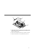
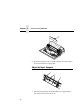
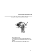
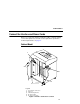
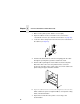
Table Of Contents
- 1 Introduction
- 2 Setting Up the Printer
- 3 Operating the Printer
- 4 The Configuration Menus
- Configuration Overview
- CONFIG. CONTROL
- ACTIVE EMULATION
- EMULATION
- PCL-II Emulation
- LinePrinter Plus Emulations
- Optional Emulations
- PCL-II Emulation
- LinePrinter Plus Emulation
- P-Series Emulation
- Proprinter XL Emulation
- Epson FX Emulation
- IGP/PGL Submenu
- Features
- Configuring the Emulation with the Control Panel
- Define CR Code (Carriage Return)
- Define LF Code (Line Feed)
- Autowrap
- Select SFCC
- PI Slew Range
- CR Edit
- Select Font
- Select LPI
- Auto Uppercase
- Skip Command Prefix
- Power On IGP/PGL
- Extended Execute Copy
- UPC Descenders
- Compressed CPI
- Ignore Character
- IGP100 Compatbl.
- Optimized Ratio
- IGP/VGL Emulation
- MAINT / MISC
- HOST INTERFACE
- ETHERNET PARAMETERS
- PRINTER CONTROL
- DIAGNOSTICS
- RIBBONMINDER
- 5 Interfaces
- Overview
- Dataproducts Long Line Interface
- IEEE 1284 Parallel Interface
- RS-232 and RS-422 Serial Interfaces
- Host System Configuration
- Internal Ethernet Adapter Configuration
- Configuring the Internal Ethernet Adapter for TCP/IP
- Host Software
- Compiling Host Software
- Computer-aided Configuration with ezsetup or npconfig
- Configuration Through the Network with ARP
- Configuration Through the Network with RARP
- Configuration Through the Network with BOOTP
- Restoring Factory Defaults
- Host Configuration
- Direct Printing Without Spooler
- Printing Via the Spooler
- Custom Interface Scripts
- BSD UNIX
- System V UNIX
- npd Pseudo-device Interface
- Other TCP/IP Methods
- Configuring The Internal Ethernet Adapter For Novell
- Configuring the Internal Ethernet Adapter for Windows
- 6 Troubleshooting
- A Printer Specifications
- B Downloading Firmware
- C ASCII Character Set
- D Communication and Trademark Information
Chapter 2 Connect the Interface and Power Cords
28
1. Make sure the printer power switch is set to O (Off).
2. Open the cabinet rear door, and remove the cover from the
selected I/O connector. (See “Interface Connections” on page 30.)
3. Locate the cable routing notch in the lower left corner of the back of
the cabinet (see Figure 5).
4. Hold the I/O cable below its connector and gently push the cable
through the opening in the grommet seated in the notch.
5. Pull the cable up through the notch until it reaches the I/O plate.
Attach the cable connector to the printer interface connector
previously selected in step 2 of this section. Secure the cable to the
printer using the upper and lower standoffs.
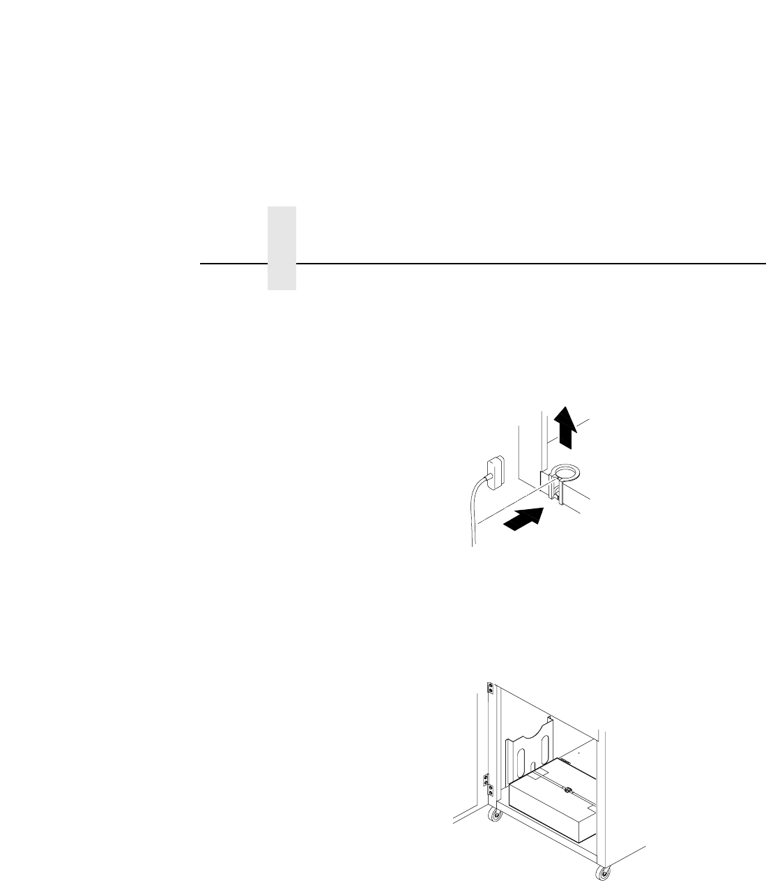
6. Open the cabinet front door and cut the strap that secures the box,
which contains the power cord, printer ribbon, control panel overlay
labels, and documentation.
7. Open the box and remove the power cord, overlays, and
documentation.