
6100 ADCCP Programming Manual

6100 ADCCP Concepts and Context
Introduction to 6100 ADCCP
069225 Tandem Computers Incorporated 1–9
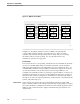
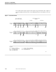
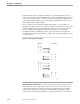
Figure 1-5. ADCCP Frame Format
Legend
003
Flag
8 bits
Address
Field
8 bits
Control
Field
8 bits
Frame Check
Sequence Field
16 bits
Flag
8 bits
∗
∗
F A C FCS F
Information Field
(variable)
In extended mode, the address field can be up to 4 bytes
long, or the control field can be up to 2 bytes long, or both.
∗
I
Flag Sequence
All frames begin and end with a flag sequence. This flag sequence consists of a
leading zero bit followed by six one bits and a trailing zero bit. All stations constantly
monitor the line for the flag sequence, which indicates the start of a message frame and
provides for synchronization timing. The same flag that closes one frame may begin
the next frame, reducing some of the line overhead for sequential (back-to-back)
messages. ADCCP can send two frames separated by one flag and can handle back-to-
back incoming frames.
Flags can also be transmitted continuously when the line is idle. You indicate whether
flags or ones should be used for this purpose by declaring the FLAGIDLE parameter at
system generation (SYSGEN) or in the configuration block.
Address Field
The address field immediately follows the starting flag. The address field specifies
which stations on a link are exchanging frames. For example, when a primary station
polls a secondary station on a multipoint link, the address specifies the secondary that
the poll is intended for. In its reply, the secondary uses the same address. In general,
a secondary station has one address, and a primary station has one address for each
secondary that it controls. A combined station has two addresses: one for the primary
substation it uses to address a remote combined station, and one for the secondary
substation it uses in responding to a remote combined station. Figure 1-6 shows these
principles of addressing.