
6100 ADCCP Programming Manual


Link States and Transitions
ADCCP/X21 Protocol Module
3–8 069225 Tandem Computers Incorporated
Link States and
Transitions
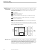
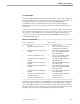
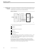
The X.21 interface is defined between host data-terminal equipment (DTE) and an X.21
modem (DCE) that is connected to an X.21 network. Figure 3-2 shows the six circuits
that make up the X.21 interface between the DTE and the DCE.
Figure 3-2. X.21 Circuits
Modem
(DCE)
X.21
LIU
(DTE)
To Host
X.21
Network
transmit (t)
control (c)
receive (r)
indication (i)
signal timing (s)
byte timing (b)
014
The DTE controls the following circuits:
Transmit (t)
Control (c)
The DCE controls the following circuits:
Receive (r)
Indication (i)
Signal element timing (s)
Byte timing (b)
User data and X.21 interface control information are transmitted on circuits t, c, r, and
i. Circuits s and b transmit timing signals. Circuit b is an optional X.21 circuit that
may not be provided on all modems. It is required, however, for networks that use
selective direct call procedures.
Link states at the X.21 interface are defined by sequences of signals transmitted
between the DTE on circuits t and c and the DCE on circuits r and i. Knowing the
values of these four circuits, however, is not always sufficient to determine the state of
the link unless you also know the preceding sequence of states.