
6530 Programmer's Guide

Block Mode Operation
3-34
6530 Programmer’s Guide
Limitations
Whether implemented with CGA, EGA, or VGA BIOS, the 6530’s
Enhanced Color Field control codes can only be invoked to use sixteen
colors, regardless of the number of colors available in the BIOS
specification. This means:
When implemented with CGA, the 6530 is capable of controlling all
available colors, including the designation of any of the first eight
colors as background colors.
When implemented with an EGA BIOS, a choice of any 16 of the
64 available colors must be made.
When implemented with VGA BIOS, a choice of any 16 of the 256
colors available must be made. The 6530 uses VGA mode 3 (color
text).
Enhanced Color Field control codes are constructed by first identifying
whether the setting is for foreground (hex 42) or background (hex 45),
then sending the register color value (in hex) added to a hex 20.
For example, to set the foreground color to light red (register 12) the data
field should contain a hex 42 (select foreground color) followed by a hex
2C (0C+20H=2CH). To set the background color to magenta (register
05), the data field should contain a hex 45 (select background color)
followed by a hex 25 (05+20H=25H).
Default colors are: foreground = red, background = black.
Read Screen With All Attributes (Esc Q)
The Esc Q sequence reads all data on the screen, including all attributes.
This function is similar to the Esc = sequence; only those fields with the
MDT set are sent. The format of the new sequence is:
Esc Q
p1 p2 p3 p4
1B 51
parameters
(hex values)
where:
p1
is the row specification of the starting buffer address
p2
is the column specification of the starting buffer address
p3
is the row specification of the ending buffer address
p4
is the column specification of the ending buffer address
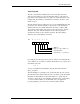
The attribute locations are transmitted with the following format:
RS
vid1 da1 da2
pair cnt data pairs