
6530 Programmer's Guide


Block Mode Operation
6530 Programmer’s Guide
3-85
p2
specifies the column on the display at which the redefined video
attributes begin. The format is the same as that of the “Set Buffer
Address (DC1)” on page 3-15.
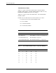
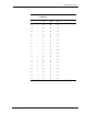
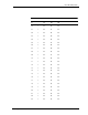
p3
is an ASCII character that indicates which of the two attribute
definition tables is used and specifies the attribute elements to assign
to the field, as follows:
For example, the sequence
FS H20 H2B H7E
uses row 62 of the Fixed Field Definitions table to define a field that
starts at row 1 and column 12 of the selected page of the display.
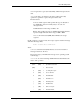
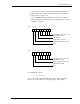
Bit 76543210
number that specifies the set of
video attributes to use
1 (mandatory)
specifies the 32-element
Variable Field Definitions table
parity
0
1
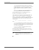
Bit 76543210
number that specifies the set of
video attributes to use
specifies the 64-element Fixed
Field Definitions table
parity
1