6763 Common Communication ServerNet Adapter Installation and Support Guide Abstract This guide describes how to install, replace, and relocate a 6763 Common Communication ServerNet adapter (CCSA) in an HP NonStop™ S-series server or in NonStop S-series I/O enclosures that are part of an HP Integrity NonStop NS-series server. This guide is written for anyone who installs or maintains a CCSA. Product Version N.A. Supported Release Version Updates (RVUs) This guide supports H06.
Document History Part Number Product Version Published 522309-002 N.A. December 2004 522309-003 N.A. July 2005 522309-004 N.A. April 2006 522309-005 N.A.
6763 Common Communication ServerNet Adapter Installation and Support Guide Glossary Index What’s New in This Guide v Guide Information v New and Changed Information About This Guide vii How This Guide is Organized Related Manuals vii Notation Conventions viii Examples Figures Tables v vii 1.
Contents 2. Installing a CCSA (continued) 2. Installing a CCSA (continued) Install a CCSA 2-5 Unpack and Inspect the CCSA 2-5 Install the CCSA 2-6 Verify the Installation of the CCSA 2-10 Install a CCSA (continued) Add and Start the CCSA Using SCF 2-12 3.
4. Relocating a CCSA (continued) Contents 4. Relocating a CCSA (continued) Remove and Relocate the CCSA 4-4 Review Standard Operating Practices 4-4 Remove the Adapter 4-4 Move the CCSA and Install It in Its New Slot Verify the Installation of the CCSA 4-4 Resume Operations 4-4 Complete the Configuration Form 4-4 Add and Start the CCSA Using SCF 4-5 Troubleshooting 4-5 4-4 A. CCSA Configuration Form B.
Figures (continued) Contents Figures (continued) Figure 1-5. Figure 1-6. Figure 1-7. Figure 1-8. Figure 1-9. Figure 1-10. Figure 2-1. Figure 2-2. Figure 2-3. Figure 2-4. Figure 2-5. Figure 3-1. Figure A-1. Figure B-1.
What’s New in This Guide Guide Information 6763 Common Communication ServerNet Adapter Installation and Support Guide Abstract This guide describes how to install, replace, and relocate a 6763 Common Communication ServerNet adapter (CCSA) in an HP NonStop™ S-series server or in NonStop S-series I/O enclosures that are part of an HP Integrity NonStop NS-series server. This guide is written for anyone who installs or maintains a CCSA. Product Version N.A.
What’s New in This Guide New and Changed Information 6763 Common Communication ServerNet Adapter Installation and Support Guide —522309-005 vi
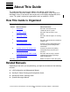
About This Guide This guide describes how to install, replace, and relocate a 6763 Common Communication ServerNet adapter (CCSA) in an HP NonStop S-series server or in NonStop S-series I/O enclosures that are part of an HP Integrity NonStop NS-series server. This guide is written for anyone who installs or maintains a CCSA. How This Guide is Organized . Table i. Guide Organization Section Name of Section What it Describes 1 Introduction Describes the CCSA and its relationship to the system.
About This Guide Notation Conventions Notation Conventions Hypertext Links Blue underline indicates a hypertext link within text. When you click on a passage of text that has a blue underline, you are taken to the location described. For example: This requirement is described under Backup DAM Volumes and Physical Disk Drives on page 3-2. General Syntax Notation The following list summarizes the notation conventions for syntax presentation in this manual. UPPERCASE LETTERS.
General Syntax Notation About This Guide | Vertical Line. A vertical line separates alternatives in a horizontal list that is enclosed in brackets or braces. For example: INSPECT { OFF | ON | SAVEABEND } … Ellipsis. An ellipsis immediately following a pair of brackets or braces indicates that you can repeat the enclosed sequence of syntax items any number of times. For example: M address-1 [ , new-value ]... [ - ] {0|1|2|3|4|5|6|7|8|9}...
About This Guide Change Bar Notation Change Bar Notation Change bars are used to indicate substantive differences between this edition of the manual and the preceding edition. Change bars are vertical rules placed in the right margin of changed portions of text, figures, tables, examples, and so on. Change bars highlight new or revised information. For example: The message types specified in the REPORT clause are different in the COBOL environment and the Common Run-Time Environment (CRE).
1 Introduction This section provides an introduction to the 6763 Common Communication ServerNet adapter (CCSA) for NonStop NS-series and NonStop S-series servers.
Overview of the CCSA Introduction Figure 1-1 shows the slots in a processor enclosure and an I/O enclosure. Figure 1-1. CCSA Slot Locations NonStop S-Series I/O Enclosures (Service Side) 50 55 51 52 53 NonStop S-Series Processor Enclosures (Service Side) 50 55 51 54 56 I/O enclosures can use slots 51 through 54 for CCSAs. 52 53 54 56 Processor enclosures can only use slots 53 and 54 for CCSAs. VST057.
Introduction CCSA Features CCSA Features • • • • • ServerNet attached PCI connectivity for NonStop systems for up to four PICs (see Plug in Cards (PICs) for SS7 ServerNet Adapters on page 1-7 for details on the number and combinations of PICs you can configure). Connections to both X and Y ServerNet fabrics in each configured slot ServerNet connectivity to 16 NonStop system hosts Diagnostics Automatic physical layer configuration for V.35, EIA-449, EIA-232, or X.21 cable types.
Introduction SLSA Subsystem Components ADAPTERs The ADAPTER SCF object is used in this guide to manage the CCSA itself. The SAC and PIF objects are subordinate to the ADAPTER object. Because of this, this guide uses examples of stopping, and starting operations on the ADAPTER and its subordinate objects. These actions automatically affect both the SACs and PIFs.
SLSA Subsystem Components Introduction Figure 1-2. Relationship to the SLSA Subsystem Processor Service Applications INS IOA Processes LIF LIF LIF LIF LAN Driver and Interrupt Handler Y Fabric X Fabric CCSA VST001.vsd Figure 1-2 also shows the X and Y fabrics on a NonStop system. Communication flow through these fabrics is affected whenever the PMF or IOMF CRUs are replaced.
Introduction Manufacturing Naming Conventions for SLSA SCF Objects Manufacturing Naming Conventions for SLSA SCF Objects HP manufacturing uses a naming convention for processes and devices that relates logical names to the group, module, and slot location of those devices. These naming conventions are presented here to familiarize you with them since they might appear in your pre-configured system. In addition, you may want to continue using these naming conventions in your own configurations.
Plug in Cards (PICs) for SS7 ServerNet Adapters Introduction Plug in Cards (PICs) for SS7 ServerNet Adapters Plug-in cards (PICs) fit onto the common base board (CBB) of the CCSA. You must purchase at least one SS7TE, SS7TE1, SS7TE2, or SS7TE3 to enable SS7 capabilities on the CCSA. For specific information about the supported OC INS software (product number T8718), PIC functions, and currently supported RVUs please contact your account representative.
Introduction • • • PIC Ports Has a higher-capacity on-board power supply than the 6763 CCSA Can support up to four SS7TE, SS7TE1, SS7TE2 and SS7TE3 PICs in any combination or location Must not be replaced with a CCSA unless it contains the combinations of PICs supported by the CCSA Figure 1-8 on page 1-15 shows a CCSA that has SS7TE, SS7TE2, and SS7TE3 PICs. Note.
SS7TE2 Ports and Cables Introduction B CCSA CCSA Figure 1-3. CCSA With 80-Pin Connectors and Splitter Cables VST002.vsd SS7TE2 Ports and Cables Each SS7TE2 contains two ports. Each port is a RJ-48C connector and can support a T1, E1, or J1 interface (one at a time). The line termination (LT) port is an “in” port, meaning that cables coming either from customer termination equipment or from another PIC connect into the LT port. The network termination (NT) port is below the LT port.
SS7TE2 Ports and Cables Introduction Daisy-Chaining SS7TE2 PICs As shown in Figure 1-9, SS7TE2 Faceplate, on page 1-16, the line termination (LT) port is always on the top of the SS7TE2 PIC. Each PIC supports four DS0 channels. Each T1 or J1 line provides 24 DS0 channels. An E1 line provides 31 DS0 channels. You need six SS7TE2 PICs to support all DS0 channels on a T1 or J1 line. To support more than four DS0 channels, you daisy-chain multiple PICs by using two-foot crossover connector cables. Note.
SS7TE3 Ports and Cables Introduction SS7TE3 Ports and Cables Each SS7TE3 contains one 10/100 Ethernet port (RJ-45 connector) and two T1/E1/J1 ports (RJ-48C connectors). T1/E1/J1 ports (RJ-48C connectors) are not used for SS7TE3 PICs. However, these ports are supported for SS7TE3 PICs. (To view PIC part numbers, from the home page of NTL, select Support and Service > Service Information > Part Numbers.) Figure 1-5, Figure 1-6, and Figure 1-7 show the cabling options for SS7TE3s. Note.
How to Determine Which PICs Are on the CCSA Introduction Figure 1-7. Cabling a Model 6763 CCSA With Two SS7TE3 PICs 6763 CCSA RJ45 PIC 0 PIC 1 Empty To Customer Termination Equipment Empty VST705.vsd How to Determine Which PICs Are on the CCSA • • • Use the OSM Service Connection or TSM Service Application to determine the PIC type. Look at the faceplate to determine the PIC type. Use SCF to determine the PIC type.
How to Determine Which PICs Are on the CCSA Introduction Using SCF to Determine the PIC Type You can also determine the PIC types on the CCSA without checking the hardware. The SCF INFO SAC DETAIL command displays a PCI Device ID field and a PCI Vendor ID field. The following table shows the values for these fields as related to the PIC type: PIC Type Device ID Vendor ID SS7TE or SS7TE1 0x860 0x10E3 SS7TE2 0x9052 0x107E SS7TE3 0x9070 0x107E Note.
External Indicators Introduction Note that the PCI Vendor ID is 0x10E3 and the PCI Device ID is 0x860 meaning that the PIC on the SAC of the CCSA named C2153 is an SS7TE or SS7TE1 PIC. (These fields display Unknown if the SAC is not STARTED.) The following example shows the output for INFO SAC DETAIL command for an adapter that includes an SS7TE2 PIC: Example 1-2. INFO SAC DETAIL Command Showing an SS7TE2 PIC -> INFO SAC $ZZLAN.C2153.0 , DETAIL SLSA Detailed Info SAC \SYS.$ZZLAN.E2153.0 *AutoFirmup.......
CCSA External Indicators Introduction Figure 1-8. CCSA External Indicators and PICs Power-On LED (green) Ejector Fault LED (amber) SS7TE PIC Empty Slot SS7TE2 PIC SS7TE3 PIC VST703.
SS7TE2 External Indicators Introduction SS7TE2 External Indicators The faceplate of the SS7TE2 PIC, with the external indicators, is shown in Figure 1-9 on page 1-16. Note. Note that Figure 1-7 shows the SS7TE2 outside the CCSA, making the PIC look bigger. For a more accurate idea of scale when installed in the CCSA, see Figure 1-8. Figure 1-9.
Introduction SS7TE3 External Indicators Figure 1-10. SS7TE3 Faceplate 10/100 Fast Ethernet Port Ethernet Full Duplex CPU Heartbeat Ethernet Speed Ethernet Link/Activity T1/E1/J1 Port 1 T1/E1/J1 Port 2 T1/E1/J1 Port 1 T1/E1/J1 Port 2 LEDs Ethernet Full Duplex: ON when the link is full duplex Ethernet Speed : ON when the link is 100 Mbps Ethernet Link/Activity LED: ON when the link is up.
Introduction SS7TE3 External Indicators 6763 Common Communication ServerNet Adapter Installation and Support Guide—522309-005 1-18
2 Installing a CCSA This section describes how to configure and install a 6763 Common Communication ServerNet adapter (CCSA) in a NonStop S-series system enclosure. This section includes the following topics: Prepare to Install a CCSA Page 2-2 Install a CCSA Page 2-5 Note. The instructions in this section assume that the software required to support the CSSA and its PICs is installed on the system.
Installing a CCSA Prepare to Install a CCSA Prepare to Install a CCSA Table 2-1. Preparation Checklist Step Description 1. Plan the SLSA Interface 2. Complete the Configuration Form 3. Gather the Proper Tools 4. Review Standard Operating Practices Plan the SLSA Interface You need to be familiar with the SLSA subsystem to plan your LIF, SAC, and PIF configuration. For information about planning the SLSA interface to control the CCSA, see the LAN Configuration and Management Manual.
Installing a CCSA Gather the Proper Tools 6. Complete the CCSA Port information block for each port on the adapter. a. Enter the SAC name. b. Indicate whether the PIC associated with the SAC is an SS7TE or SS7TE1, an SS7TE2, or an SS7TE3 by checking the appropriate box. c. Enter the numbers of the processors that will have access to the SAC in the SAC Access List field. The first processor listed is the preferred processor. d. Enter the PIF names associated with the SAC in the PIF Name fields. e.
Installing a CCSA Review Standard Operating Practices Figure 2-1. ESD-Protected Environment System Enclosure (Appearance Side) ESD wriststrap with clip ESD wriststrap clipped to door latch stud (or to any exposed, unpainted, metal surface on the enclosure frame.) ESD floor mats ESD antistatic table mat. Mat should be connected to a soft ground . (1 megohm min. to 10 megohm max.) Clip 15 inch straight ground cord to screw on grounded outlet cover. VST693.
Installing a CCSA Install a CCSA Install a CCSA Note. HP recommends that you install a CCSA first, then add the adapter using the Subsystem Control Facility (SCF). Table 2-2. Installation Checklist Step Description 1. Unpack and Inspect the CCSA. 2. Install a CCSA. 3. Verify the Installation of the CCSA. 4. Add and Start the CCSA Using SCF. Unpack and Inspect the CCSA Note. Whenever you handle a CCSA, follow standard operating practices to avoid damage to the equipment.
Installing a CCSA Install the CCSA Install the CCSA 1. Disconnect the grounding clip of your ESD wrist strap from the antistatic mat, then connect it to an unpainted metal surface on the CCSA. 2. Grasp the CCSA by its ejector in one hand, while supporting the bottom edge of the CCSA with the other hand. a. Carry the CCSA to the service side of the system enclosure. b. Set the CCSA down on an antistatic mat rightside up with the ejector at the top. Note. The CCSA weights 6.75 pounds (3 kilograms). 3.
Installing a CCSA Install the CCSA 4. Unlatch the ejector on the adapter and pull the ejector upward into its full-open position: VST500.
Installing a CCSA Install the CCSA 5. Using both hands, hold the CCSA so that its ejector is at the top. a. Carefully insert the adapter into its slot in the enclosure. b. Push the CCSA to the rear of its slot, but don't force it. Caution. To avoid damaging the connector pins, apply equal pressure to both the top and bottom of the CCSA when pushing it into its slot. If the pins are damaged, both the CCSA and the backplane (or enclosure) must be replaced. 6.
Installing a CCSA Install the CCSA 8. For the SS7TE or SS7TE1 PIC, starting at the bottom (to prevent having cables hanging in your way), connect the splitter cables to the 80-pin ports on the CCSA. Connect the other ends of the cables to your customer termination equipment. VST118.vsd 9. For the SS7TE2 PIC, connect the RJ-48C cable from your customer termination equipment to the LT (line termination) port on the top SS7TE2.
Installing a CCSA Verify the Installation of the CCSA Note. The SCF labels that you must use to configure a CCSA are different than the labels physically located on the CCSA. The SCF labels are 0 (zero) origin, with 0 corresponding to the bottom most SAC proceeding upward. The physical CCSA labels are 1 origin, with 1 corresponding to the bottom most SAC proceeding upward. Figure 2-3. Cabling a CCSA That Has Four SS7TE2 PICs 6763-2 CCSA To Customer Termination Equipment PIC 0 PIC 1 PIC 2 PIC 3 VST004.
Installing a CCSA Verify the Installation of the CCSA ° Check the CCSA and backplane connector for damaged pins. If the CCSA or backplane connector has damaged pins, both the CCSA and backplane (or enclosure) must be replaced. If the backplane must be replaced, contact your service provider. ° Use the OSM Service Connection or the TSM Service Application to check for alarms related to the CCSA. Figure 2-5.
Installing a CCSA Add and Start the CCSA Using SCF Add and Start the CCSA Using SCF With your completed CCSA configuration form as a guide, use the SCF interface to the SLSA subsystem to add and start the CCSA. Note. Refer to the LAN Configuration and Management Manual for detailed information about the SLSA subsystem SCF commands. Adding and Starting the CCSA 1.
Installing a CCSA Add and Start the CCSA Using SCF 2. Using the SCF ADD LIF command, add the LIFs and PIFs: ADD LIF $ZZLAN.lifname, PIF adapter-name.sac#.pifid LIF lifname is the name of the LIF. The suggested naming convention for LIFs is Lgroupid-slot-sac#-pifid where L represents LIF, groupid is the group number, slot is the slot number, sac# is the SAC number and pifid is a letter in the range A to D matching the PIF associated with that LIF. PIF adapter-name.sac#.
Installing a CCSA Add and Start the CCSA Using SCF 3. Start the CCSA ADAPTER object and its subordinate SAC and PIF objects by using one of these methods: • Use the SCF START ADAPTER command with the SUB ALL option. START ADAPTER $ZZLAN.adapter-name, SUB ALL The SUB ALL option starts the ADAPTER object and its subordinate objects. • Use the OSM Service Connection: 1. Log on to the OSM Service Connection. 2. In the Tree pane, select the CCSA. 3. Right-click the CCA.
Installing a CCSA Add and Start the CCSA Using SCF Example 2-2. SCF STATUS Commands ->STATUS ADAPTER $ZZLAN.C2153 SLSA Status ADAPTER Name $ZZLAN.C2153 State STARTED -> STATUS SAC $ZZLAN.C2153.* SLSA Status SAC Name $ZZLAN.C2153 Owner 0 0 State STARTED -> STATUS PIF $ZZLAN.C2153.* SLSA Status PIF Name $ZZLAN.C2153.0.A State STARTED -> STATUS LIF $ZZLAN.L21* SLSA Status LIF Name $ZZLAN.
Installing a CCSA Add and Start the CCSA Using SCF Troubleshooting If the SCF STATUS SAC command shows that the CCSA SAC object is still in the STARTING state after a few minutes or if the OSM Service Connection or TSM Service Application indicates that the resource needs attention: 1. Check for event messages in the Event Message Service (EMS) log. Use the OSM or TSM Event Viewer Application to view the EMS log: 1. From the File menu, select Log on. 2. Select the system. 3.
Installing a CCSA f. Add and Start the CCSA Using SCF Double-click on the resource. The resource is displayed in the Selected list box. g. Click Perform action to initiate the firmware update. For information about configuring the SLSA subsystem, refer to the LAN Configuration and Management Manual.
Installing a CCSA Add and Start the CCSA Using SCF 6763 Common Communication ServerNet Adapter Installation and Support Guide—522309-005 2- 18
3 Replacing a CCSA This section describes how to perform online replacement of a 6763 Common Communication ServerNet adapter (CCSA) in a NonStop S-series system. You might need to replace a CCSA if it has failed or partially failed. Note. A CCSA can be replaced without shutting down the system. Caution. If a previously installed CCSA and backplane connector have damaged pins, remove the CCSA and install a filler panel (U09021) in the empty slot. Attach red tags to the filler panel to identify the slot.
Replacing a CCSA Prepare to Replace a CCSA Prepare to Replace a CCSA ServerNet adapter slots should not be left empty for long periods of time. If you remove a ServerNet adapter without replacing it, a ServerNet adapter filler panel (U09021) must be installed in the empty slot to maintain proper air flow and to reduce electromagnetic interference (EMI). Service Class A CCSA is a Service Class-2 customer-replaceable unit (CRU).
Replacing a CCSA Print the CCSA Configuration Form Print the CCSA Configuration Form Print Figure 3-1 and use it to record information about the adapter. For a completed configuration form, see Figure A-1 on page A-3 Figure 3-1.
Replacing a CCSA Redirect or Stop Any Applications Using the CCSA Redirect or Stop Any Applications Using the CCSA Before continuing with this procedure, ensure that stopping your CCSA will not cause problems for applications using the adapter. Refer to your application guides to stop the applications before terminating their links. Note. The actions required to perform this step depend on the applications using the adapter.
Replacing a CCSA Abort the CCSA Abort the CCSA 1. Use the SCF ABORT LIF command for each LIF to stop access to the LIF associated with the CCSA to be replaced. ABORT LIF $ZZLAN.lif-name 2. Use the SCF STATUS LIF command to verify that the associated LIF is in the STOPPED state (see Example 3-2). STATUS LIF $ZZLAN.* Example 3-2. SCF STATUS LIF Command ->STATUS LIF $ZZLAN.* SLSA Status LIF Name $ZZLAN.L218 State STOPPED Access State UP 3.
Replacing a CCSA Label the Communications Cables Connected to the CCSA 4. Use the SCF STATUS ADAPTER command to verify that the CCSA ADAPTER object is in the STOPPED state (see Example 3-3). STATUS ADAPTER $adapter-name Example 3-3. SCF STATUS ADAPTER Command ->STATUS ADAPTER $ZZLAN.C2153 SLSA Status ADAPTER Name $ZZLAN.C2153 State STOPPED Label the Communications Cables Connected to the CCSA 1. Find the group, module, and slot in which the CCSA is installed (see Figure 1-1 on page 1-2). 2.
Replacing a CCSA Unpack and Inspect the CCSA Unpack and Inspect the CCSA Follow the procedure described in Unpack and Inspect the CCSA on page 2-5. Remove the Adapter 1. Disconnect the communication cable from the CCSA. 2.
Replacing a CCSA Install the CCSA 3. Unlatch the ejector on the CCSA by pressing the blue-green tab on the ejector and pulling the ejector outward to unseat the CCSA from its backplane. VST059.vsd 4. Grasp the CCSA by its ejector in one hand and slowly pull the CCSA out of the slot while supporting the bottom edge of the CCSA with the other hand. Note. The CCSA weighs 6.75 pounds (3 kilograms). Install the CCSA Follow the procedure described in Install the CCSA on page 2-6.
Replacing a CCSA Verify the Installation of the CCSA Verify the Installation of the CCSA Follow the procedure described in Verify the Installation of the CCSA on page 2-10. Resume Operations Table 3-3. Resuming Operations Checklist Step Description 1. Start the CCSA 2. Restart the Communications Lines 3. Verify that the Communications Lines are Restarted 4.
Replacing a CCSA Start the CCSA Using SCF to Verify that Objects Are in the STARTED State 1. Use the SCF STATUS ADAPTER command to verify the adapter is in the STARTED state (see Example 3-4). STATUS ADAPTER $ZZLAN.adapter-name.* Example 3-4. SCF STATUS ADAPTER command ->STATUS ADAPTER $ZZLAN.C2153 SLSA Status ADAPTER Name $ZZLAN.C2153.0 State STARTED 2. Use the SCF STATUS SAC command to verify that the ServerNet addressable controller (SAC) is in the STARTED state (see Example 3-5). STATUS SAC $ZZLAN.
Replacing a CCSA Restart the Communications Lines 4. Use the SCF START LIF command to start the logical interface (LIF). START LIF $ZZLAN.lif-name 5. Use the SCF STATUS LIF to verify that the LIF is in the STARTED state (see Example 3-7). STATUS LIF $ZZLAN.* Example 3-7. SCF STATUS LIF command ->STATUS LIF $ZZLAN.* SLSA Status LIF Name $ZZLAN.
Replacing a CCSA Resume Customer Applications 6763 Common Communication ServerNet Adapter Installation and Support Guide—522309-005 3- 12
4 Relocating a CCSA This section describes how to relocate a 6763 Common Communication ServerNet adapter (CCSA) that has been previously installed in a NonStop S-series system enclosure. Note. A CCSA can be replaced without shutting down the system. Caution. If a previously installed CCSA and backplane connector have damaged pins, remove the CCSA and install a filler panel (U09021) in the empty slot. Attach red tags to the filler panel to identify the slot.
Relocating a CCSA Prepare to Relocate a CCSA Prepare to Relocate a CCSA ServerNet adapter slots should not be left empty for long periods of time. If you remove a ServerNet adapter without replacing it, a ServerNet adapter filler panel (U09021) must be installed in the empty slot to maintain proper air flow and to reduce electromagnetic interference (EMI). Table 4-1. Relocation Checklist Step Description 1. Gather the Proper Tools 2. Print the CCSA Configuration Form 3.
Relocating a CCSA Print the CCSA Configuration Form Print the CCSA Configuration Form Follow the procedure described in Print the CCSA Configuration Form on page 3-3. Redirect or Stop Any Applications Using the CCSA Follow the procedure described in Redirect or Stop Any Applications Using the CCSA on page 3-4. Determine the Physical Location of the CCSA Follow the procedure described in Determine the Physical Location of the CCSA on page 3-4.
Relocating a CCSA Remove and Relocate the CCSA Remove and Relocate the CCSA Table 4-2. Remove and Relocate Checklist Step Description 1. Review Standard Operating Practices. 2. Remove the Adapter. 3. Move the CCSA and Install It in Its New Slot. 4. Verify the Installation of the CCSA. Note. Whenever you handle a CCSA, follow standard operating practices to avoid damage to the equipment.
Relocating a CCSA Add and Start the CCSA Using SCF Add and Start the CCSA Using SCF Using your completed CCSA configuration form as a guide, follow the procedure described in Add and Start the CCSA Using SCF on page 2-12.
Relocating a CCSA Troubleshooting 6763 Common Communication ServerNet Adapter Installation and Support Guide—522309-005 4 -6
A CCSA Configuration Form A blank 6763 Common Communication ServerNet adapter (CCSA) configuration form follows on the next page. You should make several copies of this form when you are planning a new system or additions to a system. You are authorized to photocopy these forms only for the purpose of installing and configuring your HP system. For a completed configuration form, see Figure A-1 on page A-3.
CCSA Configuration Form 6763 Common Communication ServerNet Adapter Configuration Form System Name Date Group Slot Module Adapter Name: SAC 3 SAC Name: Access List SS7TE SS7TE2 PIF Name: PIF Name: LIF Name: PIF Name: PIF Name: LIF Name: SAC 2 SAC Name: Access List PIF Name: PIF Name: LIF Name: LIF Name: SS7TE SS7TE3 LIF Name: LIF Name: LIF Name: SS7TE SS7TE2 SS7TE3 LIF Name: PIF Name: PIF Name: LIF Name: LIF Name: PIF Name: PIF Name: SAC 0 SAC Name: Access List SS7TE2 LIF Name: PIF
CCSA Configuration Form Figure A-1. Completed CCSA Configuration Form 6763 Common Communication ServerNet Adapter Configuration Form \Casel System Name 01 / 02 Date Group 21 Adapter Name: SAC 3 SAC Name: C2153.4 Access List 0, 1, 2, 3, 4, 5 PIF Name: PIF Name: Port Information Blocks PIF Name: PIF Name: SS7TE X SS7TE2 LIF Name: C2153.4.A C2153.4.B C2153.4.C C2153.4.D LIF Name: LIF Name: LIF Name: SAC 2 SAC Name: C2153.3 SS7TE X SS7TE2 Access List 0, 1, 2, 3, 4, 5 LIF Name: C2153.3.
CCSA Configuration Form 6763 Common Communication ServerNet Adapter Installation and Support Guide—522309-005 A- 4
B SS7TE2 and SS7TE3 Pinouts and Cable Requirements This appendix shows the pinouts for the SS7TE2 and SS7TE3 PIC cables and provides the cable requirements. The SS7TE2 uses CAT 5, 26AWG minimum cables. The daisy-chain crossover cables are two feet long and must have ferrite beads clipped on to both ends. In addition, a ferrite bead must be clipped onto the cable that connects to the customer termination equipment. The SS7TE3 uses CAT 5 26AWG minimum cables.
SS7TE2 and SS7TE3 Pinouts and Cable Requirements SS7TE2 and SS7TE3 Connector Pinouts 1. With a ferrite bead open, position it around a SS7TE2 cable at a distance of 7.6 to 10.2 cm (3 to 4 in) from the RJ-48C connector on the cable that is to be plugged into the SS7TE2. 2. Close the ferrite bead around the cable and clamp the bead in place with its latch. 3. Verify that the distance between the cable connector and installed ferrite bead is as stated in Step 1.
SS7TE2 and SS7TE3 Pinouts and Cable Requirements SS7TE2 and SS7TE3 Connector Pinouts Table B-2.
SS7TE2 and SS7TE3 Pinouts and Cable Requirements SS7TE2 and SS7TE3 Connector Pinouts The connector pinouts for the 10/100 Fast Ethernet RJ-45 connector are as follows: Table B-3.
Safety and Compliance This sections contains three types of required safety and compliance statements: • • • Regulatory compliance Waste Electrical and Electronic Equipment (WEEE) Safety Regulatory Compliance Statements The following regulatory compliance statements apply to the products documented by this manual. FCC Compliance This equipment has been tested and found to comply with the limits for a Class A digital device, pursuant to part 15 of the FCC Rules.
Safety and Compliance Regulatory Compliance Statements Korea MIC Compliance Taiwan (BSMI) Compliance Japan (VCCI) Compliance This is a Class A product based on the standard or the Voluntary Control Council for Interference by Information Technology Equipment (VCCI). If this equipment is used in a domestic environment, radio disturbance may occur, in which case the user may be required to take corrective actions.
Safety and Compliance Regulatory Compliance Statements European Union Notice Products with the CE Marking comply with both the EMC Directive (89/336/EEC) and the Low Voltage Directive (73/23/EEC) issued by the Commission of the European Community.
Safety and Compliance SAFETY CAUTION SAFETY CAUTION The following icon or caution statements may be placed on equipment to indicate the presence of potentially hazardous conditions: DUAL POWER CORDS CAUTION: “THIS UNIT HAS MORE THAN ONE POWER SUPPLY CORD. DISCONNECT ALL POWER SUPPLY CORDS TO COMPLETELY REMOVE POWER FROM THIS UNIT." "ATTENTION: CET APPAREIL COMPORTE PLUS D'UN CORDON D'ALIMENTATION. DÉBRANCHER TOUS LES CORDONS D'ALIMENTATION AFIN DE COUPER COMPLÈTEMENT L'ALIMENTATION DE CET ÉQUIPEMENT".
Safety and Compliance Waste Electrical and Electronic Equipment (WEEE) HIGH LEAKAGE CURRENT To reduce the risk of electric shock due to high leakage currents, a reliable grounded (earthed) connection should be checked before servicing the power distribution unit (PDU).
Safety and Compliance Important Safety Information Statements -6
Glossary AWG. American Wiring Gauge. A U.S. measurement standard of the diameter of non-ferrous wire, which includes copper and aluminum. CAT 5. Specifies the transmission capacity of a wire. Category 5 UTP wires have 100Mbps transmission capacity. CCSA. See Common Communications ServerNet adapter. Common Communications ServerNet adapter. The name for the 6763 adapter as it is configured in SLSA. customer-replaceable unit (CRU).
Glossary HP NonStop™ NS-series servers HP NonStop™ NS-series servers. The HP NonStop servers having product numbers beginning with the letters NS. These servers implement the ServerNet architecture and run the HP NonStop operating system. HP NonStop™ S-series servers. The HP NonStop servers having product numbers beginning with the letter S. These servers implement the ServerNet architecture and run the HP NonStop operating system.. HP NonStop™ servers.
Glossary port port. (1) A data channel that connects to other devices or computers. (2) A connector to which a cable can be attached. (3) The entrance or physical access point (such as a connector) to a computer, multiplexer, device, or network where signals are supplied, extracted, or observed. SAC. See ServerNet addressable controller (SAC). SCP. See Service Control Point (SCP). ServerNet addressable controller (SAC).
Glossary SS7TE SS7TE. A plug-in card (PIC) for the 6763 Common Communications ServerNet adapter that provides support for the EIA-449, V.35, X.21, EIA-232 interfaces. Replaced by the SS7TE1 PIC. SS7TE1. A plug-in card (PIC) for the 6763 Common Communications ServerNet adapter that provides support for the EIA-449, V.35, X.21, EIA-232 interfaces. Replaced the SS7TE PIC. SS7TE2.
Index Numbers 6763 See CCSA 6763-2 See CCSA 80-pin connector 1-8 A Aborting the CCSA 3-5 Access list 2-12 ADAPTER SCF object 1-3 Adding the CCSA 2-12 C Cabling labels for 3-6 requirements B-1 SS7TE2 PIC 2-9 SS7TE3 PIC 1-10, 2-9 CCSA aborting 3-5 adding and starting 2-12 CCSA product number 1-7 PIC combinations supported 1-7 CCSA-2 product number 1-7 PIC combinations supported 1-7 configuration form 3-3, A-1 configuring 2-12 external indicators 1-14 features 1-3 installing 2-1/2-17 introduction 1-1 LEDs 1-
Index E E L EIA-232 1-7, 1-8 EIA-449 1-8 ESD antistatic mat 2-5 illustration of ESD-protected environment 2-4 protection kit 2-3 wrist strap 2-5 Event Message Service (EMS) log 2-16 Events EMS 2-16 External indicators CCSA and PICs 1-14 Labeling cables 3-6 LEDs CCSA 1-14 PICs 1-14 SS7TE2 PIC 2-11 LIFs naming convention for 1-6 objects 1-4 PICs, corresponding 1-4 starting 3-11 Line termination port 1-9 logical interfaces (LIFs) See LIFs LT port 1-9 F Faceplates PICs 1-12 Features CCSA 1-3 Filler panel
Index P P R Physical interfaces (PIFs) See PIFs PIC See PICs PICs configuration form 2-3 determining type, using faceplate 1-12 determining type, using SCF 1-12 external indicators 1-14 faceplate for SS7TE2 1-16 faceplate for SS7TE3 1-17 faceplates 1-12 LEDS 1-14 on CCSA 1-7 on CCSA-2 1-8 operating state, checking 1-4 PIFs, corresponding 1-3 ports 1-8 SS7TE 1-7 SS7TE1 1-7 SS7TE2 1-7, 1-9 SS7TE3 1-7 types 1-7 PIFs 1-3 naming convention for 1-6 PICs, corresponding 1-3 Pinouts B-1 Plug in Cards (PICs) see
Index T SS7TE2 PIC cabling 2-9 connector pinouts B-2 daisy-chaining 1-10, B-2 description 1-9 external indicators 2-11 faceplate 1-16 LIFs 1-4 LIFs, corresponding 1-4 PIFs, corresponding 1-3 ports 1-8 SS7TE3 PIC 1-7 cabling 1-10, 2-9 connector pinouts B-2 faceplate 1-17 LIFs, corresponding 1-4 PIFs, corresponding 1-3 ports 1-8 Standard operating practices 2-3 Starting CCSA 3-9 LIFs 3-11 ST-2000 1-1 X X.