
6763 Common Communication ServerNet Adapter Installation and Support Guide

Introduction
6763 Common Communication ServerNet Adapter Installation and Support Guide—522309-005
1-10
SS7TE2 Ports and Cables
Daisy-Chaining SS7TE2 PICs
As shown in Figure 1-9, SS7TE2 Faceplate, on page 1-16, the line termination (LT)
port is always on the top of the SS7TE2 PIC. Each PIC supports four DS0 channels.
Each T1 or J1 line provides 24 DS0 channels. An E1 line provides 31 DS0 channels.
You need six SS7TE2 PICs to support all DS0 channels on a T1 or J1 line. To support
more than four DS0 channels, you daisy-chain multiple PICs by using two-foot
crossover connector cables.
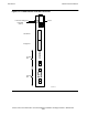
To increase DS0 channels beyond 16, which is the maximum available on a CCSA that
has four SS7TE2 PICs, daisy-chain from the bottom NT port on the CCSA to an LT
port on a SS7TE2 on another CCSA.
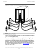
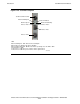
Figure 1-4 shows the cabling configuration for a CCSA equipped with four SS7TE2
PICs that are daisy-chained.
Refer to Appendix B, SS7TE2 and SS7TE3 Pinouts and Cable Requirements for
information about the pinouts of the connectors on the faceplate of the SS7TE2 and
SS7TE3 and for important safety considerations regarding SS7TE2 and SS7TE3
cables.
Note. Because the line termination (LT) and network termination (NT) ports are wired
identically, you must use a crossover cable to daisy-chain SS7TE2 PICs.
Note. The SCF labels that you must use to configure a CCSA are different than the labels
physically located on the CCSA. The SCF labels are 0 (zero) origin, with 0 corresponding to
the bottom most SAC proceeding upward. The physical CCSA labels are 1 origin, with 1
corresponding to the bottom most SAC proceeding upward.
Figure 1-4. CCSA Cabling Scheme for Four SS7TE2s
PIC 1
PIC 0
6763-2 CCSA
To Customer Termination
Equipment
VST004.vsd
PIC 3
PIC 2