
6763 Common Communication ServerNet Adapter Installation and Support Guide


Installing a CCSA
6763 Common Communication ServerNet Adapter Installation and Support Guide—522309-005
2-10
Verify the Installation of the CCSA
Verify the Installation of the CCSA
Verify the installation of the CCSA by examining the CCSA’s status LEDs. Figure 2-5
on page 2-11 shows the location of these LEDs.
•
Make sure that the power-on LED (green light) is lit.
•
If the power-on LED is not lit:
°
Reseat the CCSA. If the power-on LED is not lit after you reseat the CCSA,
replace the CCSA.
Note. The SCF labels that you must use to configure a CCSA are different than the labels
physically located on the CCSA. The SCF labels are 0 (zero) origin, with 0 corresponding to
the bottom most SAC proceeding upward. The physical CCSA labels are 1 origin, with 1
corresponding to the bottom most SAC proceeding upward.
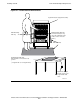
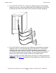
Figure 2-3. Cabling a CCSA That Has Four SS7TE2 PICs
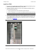
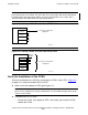
Figure 2-4. Cabling a CCSA That Has Two SS7TE3 PICs
Note. When the adapter is inserted, the fault LED (amber) remains lit until the service
processor has completed its start-up configuration. The fault LED also lights when SLSA
detects a POST failure.
PIC 1
PIC 0
6763-2 CCSA
To Customer Termination
Equipment
VST004.vsd
PIC 3
PIC 2
PIC 1
PIC 0
6763 CCSA
RJ45 or
RJ-48C
To Customer Termination
Equipment
Empty
Empty
VST704.vsd