
6763 Common Communication ServerNet Adapter Installation and Support Guide


SS7TE2 and SS7TE3 Pinouts and Cable
Requirements
6763 Common Communication ServerNet Adapter Installation and Support Guide—522309-005
B-2
SS7TE2 and SS7TE3 Connector Pinouts
1. With a ferrite bead open, position it around a SS7TE2 cable at a distance of 7.6 to
10.2 cm (3 to 4 in) from the RJ-48C connector on the cable that is to be plugged
into the SS7TE2.
2. Close the ferrite bead around the cable and clamp the bead in place with its latch.
3. Verify that the distance between the cable connector and installed ferrite bead is as
stated in Step 1. If the distance requirement is not met, remove the bead and
repeat this procedure.
SS7TE2 and SS7TE3 Connector Pinouts
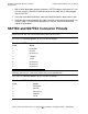
The T1/E1/J1 connector pinouts for SS7TE2 are as follows:
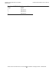
The T1/E1/J1 connector pinouts for SS7TE3 are as follows:
Note. Pinouts for the SS7TE and SS7TE1 PICs are not provided because the cables are too
complicated. HP does not recommend building cables for these PICs.
Table B-1. SS7TE2 Connector Pinouts
Pin # Signal
1 RCVRING
2 RCVTIP
3 No Connect
4TXRING
5TXTIP
6 No Connect
7 No Connect
8 No Connect
Note. Because the line termination (LT) and network termination (NT) ports are wired
identically, you must use a crossover cable to daisy-chain SS7TE2 PICs.
Table B-2. SS7TE3 T1/E1/J1 Connector Pinouts
Pin # Signal
1 RCVRING
2RCVTIP
3 No Connect
4TXRING
5TXTIP