ATM Adapter Installation and Support Guide Abstract This manual describes how to install and maintain the ATM ServerNet adapter (ATM3SA) on a NonStop™ S-series server. It is written for anyone who is responsible for installing and maintaining the ATM3SA adapter. Product Version NA Supported Release Version Updates (RVUs) This manual supports G06.22 and all subsequent G-series RVUs until otherwise indicated in a new edition.
Document History Part Number Product Version Published 140761 NA May 1998 420013-001 NA December 1998 420013-002 NA April 2004
ATM Adapter Installation and Support Guide Glossary Index What’s New in This Manual v Manual Information v New and Changed Information About This Manual vii Who Should Use This Manual What’s in This Manual vii Related Manuals vii Notation Conventions viii Examples Figures v vii 1. Overview of the ATM ServerNet Adapter (ATM3SA) ATM Subsystem Features 1-1 ATM3SA Features 1-2 Communications Lines Using the ATM3SA Adapter 1-2 2.
3. Replacing an ATM3SA Adapter (continued) Contents 3.
Examples (continued) Contents Examples (continued) Example 3-13. Example 3-14. Example 3-15. Example 3-16. SCF STATUS SUBNET Command 3-24 SCF STATUS DEVICE Command 3-24 SCF STATUS LINE Command 3-25 SCF STATUS PATH Command 3-25 Figures Figure 1-1. Figure 2-1. Figure 2-2. Figure 2-3. Figure 2-4. Figure 2-5. Figure 2-6. Figure 2-7. Figure 2-8. Figure 3-1. Figure 3-2. Figure 3-3. Figure 3-4. Figure 3-5. Figure 3-6. Figure 3-7. Figure 3-8. Figure A-1.
Contents ATM Adapter Installation and Support Guide —420013-002 iv
What’s New in This Manual Manual Information ATM Adapter Installation and Support Guide Abstract This manual describes how to install and maintain the ATM ServerNet adapter (ATM3SA) on a NonStop™ S-series server. It is written for anyone who is responsible for installing and maintaining the ATM3SA adapter. Product Version NA Supported Release Version Updates (RVUs) This manual supports G06.22 and all subsequent G-series RVUs until otherwise indicated in a new edition.
What’s New in This Manual New and Changed Information ATM Adapter Installation and Support Guide —420013-002 vi
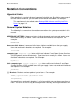
About This Manual This manual describes how to install and maintain the ATM ServerNet adapter (ATM3SA) on a NonStop S-series server. This manual includes step-by-step instructions for adding or moving an ATM3SA adapter. Who Should Use This Manual This manual is written for anyone who is responsible for installing and maintaining the ATM3SA adapter. What’s in This Manual Table i summarizes the contents of this manual. Table i. Section Title This section. . .
Notation Conventions About This Manual Notation Conventions Hypertext Links Blue underline is used to indicate a hypertext link within text. By clicking a passage of text with a blue underline, you are taken to the location described. For example: This requirement is described under Backup DAM Volumes and Physical Disk Drives on page 3-2. General Syntax Notation The following list summarizes the notation conventions for syntax presentation in this manual. UPPERCASE LETTERS.
General Syntax Notation About This Manual each side of the list, or horizontally, enclosed in a pair of brackets and separated by vertical lines. For example: FC [ num ] [ -num] [ text] K [ X | D ] address-1 { } Braces. A group of items enclosed in braces is a list from which you are required to choose one item. The items in the list may be arranged either vertically, with aligned braces on each side of the list, or horizontally, enclosed in a pair of braces and separated by vertical lines.
Notation for Messages About This Manual Line Spacing. If the syntax of a command is too long to fit on a single line, each continuation line is indented three spaces and is separated from the preceding line by a blank line. This spacing distinguishes items in a continuation line from items in a vertical list of selections. For example: ALTER [ / OUT file-spec / ] CONTROLLER [ , attribute-spec ]... !i and !o.
Notation for Messages About This Manual Nonitalic text. Nonitalic letters, numbers, and punctuation indicate text that is displayed or returned exactly as shown. For example: Backup Up. lowercase italic letters. Lowercase italic letters indicate variable items whose values are displayed or returned. For example: p-register process-name [ ] Brackets. Brackets enclose items that are sometimes, but not always, displayed.
Change Bar Notation About This Manual Change Bar Notation Change bars are indicate substantive differences between this edition of the manual and the preceding edition. Change bars are vertical rules placed in the right margin of changed portions of text, figures, tables, examples, and so on. Change bars highlight new or revised information. For example: The message types specified in the REPORT clause are different in the COBOL85 environment and the Common Run-Time Environment (CRE).
1 Overview of the ATM ServerNet Adapter (ATM3SA) The ATM ServerNet adapter (ATM3SA) is one of several supported ServerNet adapters available for use on a NonStop S-series server. The ATM3SA adapter provides a high-speed Asynchronous Transfer Mode (ATM) connection allowing NonStop S-series servers to be directly attached to an ATM network. The ATM3SA adapter operates at 155 Mbps and provides a full-duplex ATM OC-3 port for connection to the UNI (User-Network Interface).
Overview of the ATM ServerNet Adapter (ATM3SA) ATM3SA Features ATM3SA Features The ATM3SA adapter provides ATM connectivity on NonStop S-series servers, with these features: • • • • • • • • • Persistence: Each process has primary and backup ASM processes. High bandwidth: Maximum 155 megabits per second data rate between systems (over fiber-optic links). Scalability: Supports multiple processors to same adapter.
Overview of the ATM ServerNet Adapter (ATM3SA) Communications Lines Using the ATM3SA Adapter Figure 1-1 shows how HP subsystems and utilities access an ATM3SA adapter. Figure 1-1. How HP Subsystems and Utilities Access an ATM3SA Adapter Processor User Applications File System Interface Expand Socket Lib QIO Shared Memory Segment TCP/IP ATM Line ATM Drivers and Interrupt Handlers Y Fabric X Fabric ATM3SA VST005.
Overview of the ATM ServerNet Adapter (ATM3SA) Communications Lines Using the ATM3SA Adapter ATM Adapter Installation and Support Guide—420013-002 1 -4
2 Installing an ATM3SA Adapter An ATM3SA adapter can be installed without taking down the system. This procedure describes how to configure and install an ATM ServerNet adapter (ATM3SA) in a NonStop S-series server. For new systems, HP has installed, configured, and tested the adapter. See Section 3, Replacing an ATM3SA Adapter for detailed instructions about removing and replacing the adapter.
Installing an ATM3SA Adapter Plan the Local Area Network (LAN) Plan the Local Area Network (LAN) For information about planning your LAN and about network addresses, review the LAN Configuration and Management Manual, and refer, if necessary, to the following manuals: • • • NonStop S-Series Planning and Configuration Guide TCP/IP Configuration and Management Manual ATM Adapter Configuration and Management Manual Complete the Configuration Form When you add an adapter to a NonStop S-series system, you s
Installing an ATM3SA Adapter Complete the Configuration Form Figure 2-1. Completed ATM3SA Adapter Form System Name ATM ServerNet Adapter (ATM3SA) Configuration Form Group ATM \Cobow Date 9/30/03 01 Module 01 Slot 53 ATM Address: 172.16.192.20 Adapter Name: LINE Name: AM3 AM3 SAC Access List: 0,1 ServerNet ATM Adapter VST012.VSD Figure 2-2 shows the ATM3SA adapter slot locations on a NonStop S-series I/O enclosure and processor enclosure.
Installing an ATM3SA Adapter Complete the Configuration Form Figure 2-2. ATM3SA Adapter Slot Locations NonStop S-Series I/O Enclosures (Service Side) 50 55 51 52 53 NonStop S-Series Processor Enclosures (Service Side) 50 55 51 54 52 53 54 56 56 I/O enclosures can use slots 51 through 54. Processor enclosures can use slots 51 through 54. VST006.vsd Figure 2-3 shows an ATM3SA adapter installed in a system enclosure on a NonStop Sseries system.
Installing an ATM3SA Adapter Complete the Configuration Form Figure 2-3. ATM3SA Installed in a System Enclosure ATM 3 SERVERNET ADAPTER (ATM3SA) Power-On LED (green) Fault LED (amber) Ejector Transmit Receive VST002.
Installing an ATM3SA Adapter Gather the Proper Tools Gather the Proper Tools You will need the following tools to replace an adapter: Tool Used to. . . Electrostatic discharge (ESD) wriststrap with grounding clip Protect the adapter from damage caused by electrostatic discharge. Antistatic mat (recommended) Provide a static-free environment for removal and installation of an adapter. Flashlight Check the connectors for bent or broken pins.
Installing an ATM3SA Adapter Unpack and Install the ATM3SA Adapter Unpack and Install the ATM3SA Adapter The following paragraphs describe how to unpack and install the ATM3SA adapter. Note. Whenever you handle an ATM ServerNet adapter (ATM3SA), follow standard operating practices to avoid damage to the equipment. See Review Standard Operating Practices on page 2-6. Unpack the Adapter Perform the following steps: 1.
Installing an ATM3SA Adapter Unpack and Install the ATM3SA Adapter Figure 2-4. ESD Protected Environment System Enclosure (Appearance Side) ESD wriststrap clipped to door latch stud (or to any exposed, unpainted, metal surface on the enclosure frame.) ESD wriststrap with clip ESD floor mats ESD antistatic table mat. Mat should be connected to a soft ground (1 megohm min. to 10 megohm max.) Clip 15 inch straight ground cord to screw on grounded outlet cover. VST693.
Installing an ATM3SA Adapter Unpack and Install the ATM3SA Adapter Figure 2-5. Grounding Clip Processor Multifunction (PMF) or I/O Multifunction (IOMF) CRU Grounding Clip To Grounding Wriststrap VST008.vsd Install the ATM3SA Adapter 1. With the ejector on and the ATM3SA adapter in the full-open position (Figure 2-6), grasp the ATM3SA adapter by the ejector with one hand and support the bottom edge of the ATM3SA adapter with the other hand (Figure 2-7 on page 2-11).
Installing an ATM3SA Adapter Unpack and Install the ATM3SA Adapter Figure 2-6. Ejector in Full-Open Position VST500.vsd 2. Push the ATM3SA adapter to the rear of the slot, but don't force it. Caution. Apply equal pressure to both the top and bottom of the ATM3SA adapter when pushing it into the slot to avoid damaging the connector pins. If pins are damaged, both the ATM3SA adapter and the backplane (or enclosure) must be replaced. Figure 2-7 shows how to install an ATM3SA adapter.
Installing an ATM3SA Adapter Unpack and Install the ATM3SA Adapter Figure 2-7. Installing an ATM3SA Adapter VST009.vsd 3. Press the blue-green tab on the ATM3SA adapter ejector and latch the ejector to seat the ATM3SA against the backplane. 4. Disconnect the grounding clip of your ESD wriststrap from the enclosure. 5. Connect the fiber optic cables to the ATM3SA adapter.
Installing an ATM3SA Adapter Check the Installation of the ATM3SA Adapter Figure 2-8. ATM3SA Adapter Hardware Connection Status LEDs Ejector Transmit Receive ServerNet ATM Adapter Vendor ATM Switch TX RX VST010.VSD Check the Installation of the ATM3SA Adapter To check the installation of an ATM3SA adapter: 1. Make sure that the power-on LED (green light) is on. Note.
Installing an ATM3SA Adapter Use SCF to Add the ATM3SA Adapter 2. If the power-on LED does not come on, do one or both of the following: • • Reseat the ATM3SA adapter. Check the ATM3SA adapter and backplane connector for damaged pins. Note Possible Error Conditions • • If the power-on LED does not come on after you reseat the ATM3SA adapter, you must replace the ATM3SA adapter.
Installing an ATM3SA Adapter Use SCF to Add the ATM3SA Adapter 7. Use the SCF ADD PVC LINE command to add the PVC object. ->ADD PVC $AM2.#IP.PVC01, PVI 1, VCI 100 8. Use the SCF START PVC command to start the PVC object. ->START PVC $AM2.#IP.
Installing an ATM3SA Adapter Configure and Start the Communications Lines e. In the Avalable Actions list, select Firmware Update. f. • Click Perform action to initiate the firmware update. Using the TSM Service Application: 1. From the Display menu, choose Firmware Update. 2. From the Resource type pull-down menu, select the ATM3SA adapter. 3. From the Display pull-down menu, select Down-rev only.
Installing an ATM3SA Adapter Configure and Start the Communications Lines ATM Adapter Installation and Support Guide—420013-002 2- 16
3 Replacing an ATM3SA Adapter You might need to replace an ATM3SA adapter if it has failed or partially failed. This procedure describes how to replace an ATM ServerNet adapter (ATM3SA) in a NonStop S-series server that is online. You do not need to shut down the system before replacing an ATM3SA adapter. The information in this procedure is valid for all G06 RVUs. Caution.
Replacing an ATM3SA Adapter Gather the Proper Tools Table 3-2. Preparation Checklist Step Description Comments 1. Gather the Proper Tools 2. Print the ATM3SA Adapter Planning Worksheet 3. Identify Communications Lines Using the ATM3SA Adapter 4. Quiesce Any Customer Applications Using the ATM3SA Adapter 5. Stop the Communications Lines That Are Using the ATM3SA Adapter 6. Determine the Physical Location of the ATM3SA Adapter 7. Abort the ATM3SA Adapter 8.
Replacing an ATM3SA Adapter Print the ATM3SA Adapter Planning Worksheet Figure 3-1. ATM3SA Adapter Planning Worksheet ATM3SA Adapter Planning Worksheet Print this worksheet and use it to record information about an ATM ServerNet adapter (ATM3SA).
Replacing an ATM3SA Adapter Identify Communications Lines Using the ATM3SA Adapter Identify Communications Lines Using the ATM3SA Adapter Figure 1-1, How HP Subsystems and Utilities Access an ATM3SA Adapter, on page 1-3 shows how HP subsystems and utilities access an ATM3SA adapter. The following procedure helps you identify the HP subsystems and utilities that are configured to use an ATM3SA adapter. Specific instructions are provided for identifying Expand-over-IP and Expand-over-ATM lines. Note.
Replacing an ATM3SA Adapter • Identify Communications Lines Using the ATM3SA Adapter The Internet Protocol (IP) address is displayed in the IPADDRESS column Note. You can find for ATM subnets by looking in the TYPE column. ATM subnets are displayed as type ATM. In this example, which is partial output, the ATM line named $AM2 in associated with the subnet named #SN2 on the TCP/IP PROCESS NAMED $ZTC01 and has the IP address 172.16.192.20. 2.
Replacing an ATM3SA Adapter Identify Communications Lines Using the ATM3SA Adapter a. For Expand-over-ATM lines, scan the output of the command for the name of the ATM line. Make a note of the Expand-over-ATM lines that use the ATM line. b. For Expand-over-IP lines, scan the output of the command for the TCP/IP process and IP address used by the Expand-over-IP line, then compare this information to the TCP/IP processes and IP addresses that you found in Step 1.
Replacing an ATM3SA Adapter Quiesce Any Customer Applications Using the ATM3SA Adapter Example 3-6. SCF INFO LINE Command ->INFO LINE $IPYEA,DETAIL EXPAND Detailed Info LINE *Associatedev... $ZTC23 Framesize...... 132 *Timerinactivity 0:00:00.00 *AfterMaxRetries PASSIVE *Timerreconnect. 0:00:30.00 *DestIpAddr 172.17.203.37 *SrcIpAddr 172.17.208.20 $IPYEA *Maxconnects. 0 *Speed....... 74666 *Timerprobe.. 0:00:30.00 StartUp...... OFF L2Protocol... Net^IP *DestIpPort 2003 *SrcIpAddr 2003 Delay....
Replacing an ATM3SA Adapter Stop the Communications Lines That Are Using the ATM3SA Adapter Example 3-7. SCF STATUS LINE Command ->STATUS LINE $LINE1 EXPAND Status LINE Name $LINE1 State STOPPED PPID 2, 10 BPID 3, 7 CIU-Path A ConMgr-LDEV 91 Note that the line is in the STOPPED state. b. Use the SCF STATUS PATH command for an Expand multiline path: STATUS PATH $path-name Example 3-8 shows the output of these commands. Example 3-8.
Replacing an ATM3SA Adapter Determine the Physical Location of the ATM3SA Adapter 5. Stop the TCP/IP subnets associated with the Asynchronous Transfer Mode (ATM) line on the ATM ServerNet adapter (ATM3SA). Caution. Make sure that the TACL session from which you are issuing SCF commands is not running on the one of the subnets that you are about to stop. Use the SCF STOP SUBNET command: STOP SUBNET $tcpip-process-name.#subnet-name 6. Verify that the TCP/IP subnets are in the STOPPED state.
Replacing an ATM3SA Adapter Abort the ATM3SA Adapter Example 3-11. SCF INFO ADAPTER Command ->INFO ADAPTER $AM2 ATM Info ADAPTER \HANSOLO.$AM2 LOCATION (grp,mod,slot).. 1, 1, 53 ACCESSLIST................. 1, 3 AMP Filename (is use)...... \HANSOLO.$SYSTEM.SYS01.AMP *AMPFILENAME............... $SYSTEM.SYS*.AMP DownLd Filename (in use)... \HANSOLO.$SYSTEM.SYS01.C7838P00 *DLFILENAME................ $SYSTEM.SYS*.C7838P00 DownLd File Version........ T7838G02^15FEB98^06Feb98 Dump Filename (in use).....
Replacing an ATM3SA Adapter Verify That the ATM3SA ADAPTER Object Is in the STOPPED State 3. Select Abort. 4. Click Perform action. Verify That the ATM3SA ADAPTER Object Is in the STOPPED State To verify that the ATM adpater is in the stopped state you can use SCF, the OSM Service Connection, or the TSM Service Application. Using SCF 1. Issue this SCF STATUS ADAPTER command: STATUS ADAPTER $adapter-name 2. Confirm that the output of the command shows the state as STOPPED.
Replacing an ATM3SA Adapter Label the Communications Cables Connected to the ATM3SA Adapter Figure 3-2. ATM3SA Adapter Slot Locations NonStop S-Series I/O Enclosures (Service Side) 50 55 51 52 53 NonStop S-Series Processor Enclosures (Service Side) 50 55 51 54 52 53 54 56 56 I/O enclosures can use slots 51 through 54. Processor enclosures can use slots 51 through 54. VST006.
Replacing an ATM3SA Adapter Replace the ATM3SA Adapter 2. Tag each fiber optic cable connected to the ATM3SA adapter with a physical label, preferably at both ends. The label should include the following information: • • • • The logical device name assigned to the Asynchronous Transfer Mode (ATM) line. For example, $ATM2. Whether the cable should be connected to the Transmit or Receive port on the ATM3SA adapter. The Transmit port is the top port and the Receive port is the bottom port.
Replacing an ATM3SA Adapter Review Standard Operating Practices Review Standard Operating Practices Note. Whenever you handle an ATM3SA adapter, follow standard operating practices to avoid damage to the equipment. Standard operating practices include the following: • • • • Work in an electrostatic discharge (ESD) protected environment. Remove all metal accessories before working with electrical equipment. Restrain any dangling items that can get caught in equipment.
Replacing an ATM3SA Adapter Remove the ATM3SA Adapter Figure 3-3. ESD Protected Environment System Enclosure (Appearance Side) ESD wriststrap clipped to door latch stud (or to any exposed, unpainted, metal surface on the enclosure frame.) ESD wriststrap with clip ESD floor mats ESD antistatic table mat. Mat should be connected to a soft ground (1 megohm min. to 10 megohm max.) Clip 15 inch straight ground cord to screw on grounded outlet cover. VST693.
Replacing an ATM3SA Adapter Remove the ATM3SA Adapter enclosure, such as the processor multifunction (PMF) adapter or I/O multifunction (IOMF) adapter ventilation holes Figure 3-4 shows how to connect the grounding clip to the ventilation holes on the PMF adapter or IOMF adapter. Figure 3-4. Grounding Clip Processor Multifunction (PMF) or I/O Multifunction (IOMF) CRU Grounding Clip To Grounding Wriststrap VST008.vsd 3.
Replacing an ATM3SA Adapter Inspect the Replacement ATM3SA Adapter and Backplane Figure 3-5. Removing an ATM3SA Adapter VST007.vsd 5. Place the ATM3SA adapter in an ESD protective bag and return it to its original packing container. Inspect the Replacement ATM3SA Adapter and Backplane Note. Whenever you handle an ATM ServerNet adapter (ATM3SA), follow standard operating practices to avoid damage to the equipment. See Review Standard Operating Practices on page 3-14.
Replacing an ATM3SA Adapter Unpack and Install the Replacement ATM3SA Adapter close the hole in the connector-pin socket. If an ATM3SA adapter has a damaged connector-pin socket, do not install it. Caution. If you plug an ATM3SA adapter that has a damaged socket into a slot, that ATM3SA adapter's backplane pins and the connectors on other adapter boards that are plugged into that slot can be damaged. Moving a damaged board from slot to slot can damage other slots and other adapter boards.
Replacing an ATM3SA Adapter Unpack and Install the Replacement ATM3SA Adapter the ATM3SA adapter so that its ejector is at the top, as shown in Figure 3-6, and insert the ATM3SA adapter into the upper part of the carrier. Figure 3-6. Ejector in Full-Open Position VST500.vsd 2. Push the ATM3SA adapter to the rear of the slot, but don't force it. Caution. Apply equal pressure to both the top and bottom of the ATM3SA adapter when pushing it into the slot to avoid damaging the connector pins.
Replacing an ATM3SA Adapter Unpack and Install the Replacement ATM3SA Adapter Figure 3-7. Installing an ATM3SA Adapter VST009.vsd 3. Press the blue-green tab on the ATM3SA adapter ejector and latch the ejector to seat the ATM3SA against the backplane. 4. Disconnect the grounding clip of your ESD wriststrap from the enclosure. 5. Connect the fiber-optic cables to the ATM3SA adapter.
Replacing an ATM3SA Adapter Check the Installation of the Replacement ATM3SA Adapter Figure 3-8. ATM3SA Adapter Hardware Connection Status LEDs Ejector Transmit Receive ServerNet ATM Adapter Vendor ATM Switch TX RX VST010.VSD Check the Installation of the Replacement ATM3SA Adapter To check the installation of an ATM3SA adapter: 1. Make sure that the power-on LED (green light) is on. Note.
Replacing an ATM3SA Adapter Resume Operations 2. If the power-on LED does not come on, do one or both of the following: • • Reseat the ATM3SA adapter. Check the ATM3SA adapter and backplane connector for damaged pins. Note the Possible Error Conditions • • If the power-on LED does not come on after you reseat the ATM3SA adapter, you must replace the ATM3SA adapter. If the ATM3SA adapter or backplane connector have damaged pins, both the ATM3SA adapter and backplane (or enclosure) must be replaced.
Replacing an ATM3SA Adapter Start the Replacement ATM3SA Adapter Example 3-12. SCF STATUS ADAPTER Command ->STATUS ADAPTER $AM2 ATM Status ADAPTER Name $AM2 State STARTED Substate OPERATIONAL Trace OFF Time Loaded 10 Feb 1998 Note that the ADAPTER object is in the STARTED state. 2. If the ATM3SA ADAPTER object is in the STOPPED state, start it and its subordinate objects. Start the Replacement ATM3SA Adapter You need to perform this step only if the ATM3SA adapter is not in the STARTED state.
Replacing an ATM3SA Adapter Verify that the Communications Lines are Restarted 2. To start the WAN subsystem input/output processes (IOPs), use the SCF START DEVICE command: START DEVICE $ZZWAN.#device-name 3. To start the lines: To start a single line, use the SCF START LINE command: START LINE $line-name.
Replacing an ATM3SA Adapter Resume Customer Applications For a single line, use the SCF STATUS LINE command: STATUS LINE $line-name Example 3-15 shows the output of these commands. Example 3-15. SCF STATUS LINE Command ->STATUS LINE $LINE1 EXPAND Name SATHO0 Status LINE1 State STARTED PPID 2, 10 BPID 3, 7 CIU-Path A ConMgr-LDEV 91 Note that the line is in the STARTED state.
Replacing an ATM3SA Adapter Resume Customer Applications ATM Adapter Installation and Support Guide—420013-002 3- 26
A ATM3SA Adapter Configuration Form This appendix contains a blank ATM 3 ServerNet adapter (ATM3SA) configuration form. You will find a blank Processor Multifunction (PMF) CRU configuration form in the NonStop S-Series Planning and Configuration Guide. Make copies of these forms because you need several copies of each form when planning for a new system or for additions to a system. You are authorized to photocopy these forms only for the purpose of installing and configuring your NonStop S-series system.
ATM3SA Adapter Configuration Form Figure A-1. ATM3SA Adapter Configuration Form System Name Date ATM ServerNet Adapter (ATM3SA) Configuration Form Group ATM Module Slot ATM Address: Adapter Name: LINE Name: Access List:: ServerNet ATM Adapter VST011.
Safety and Compliance Regulatory Compliance Statements The following warning and regulatory compliance statements apply to the products documented by this manual. FCC Compliance This equipment has been tested and found to comply with the limits for a Class A digital device, pursuant to part 15 of the FCC Rules. These limits are designed to provide reasonable protection against harmful interference when the equipment is operated in a commercial environment.
Safety and Compliance Regulatory Compliance Statements Taiwan (BSMI) Compliance Japan (VCCI) Compliance This is a Class A product based on the standard or the Voluntary Control Council for Interference by Information Technology Equipment (VCCI). If this equipment is used in a domestic environment, radio disturbance may occur, in which case the user may be required to take corrective actions.
Safety and Compliance Regulatory Compliance Statements DECLARATION OF CONFORMITY Supplier Name: HP COMPUTER CORPORATION Supplier Address: HP Computer Corporation, NonStop Enterprise Division 10300 North Tantau Ave Cupertino, CA 95014 USA Represented in the EU By: Hewlett Packard Company P.O.
Safety and Compliance Consumer Safety Statements Consumer Safety Statements Customer Installation and Servicing of Equipment The following statements pertain to safety issues regarding customer installation and servicing of equipment described in this manual. • • Keep door closed for normal operation. Batteries must be disposed of in compliance with local ordinances. Caution.
Safety and Compliance Consignes de sécurité à l'intention du client Consignes de sécurité à l'intention du client Installation et entretien du système par le client Les consignes de sécurité qui suivent concernent l'installation et l'entretien par le client du système décrit dans le présent manuel. • • Garder la porte fermée pendant le fonctionnement normal du système. Jeter les piles usagées conformément au règlement local en vigueur. Attention.
Safety and Compliance Verbraucher-Sicherheitsangaben Verbraucher-Sicherheitsangaben Geräteinstallation und -wartung durch den Kunden Die folgenden Angaben betreffen Sicherheitsfragen in Hinsicht auf die Geräteinstallation und -wartung durch den Kunden, wie sie in diesem Handbuch beschrieben werden. • • Tür für normalen Betrieb geschlossen lassen. Batterien müssen in Übereinstimmung mit örtlichen Vorschriften beseitigt werden. Vorsicht.
Safety and Compliance Declaraciones sobre la seguridad del consumidor Declaraciones sobre la seguridad del consumidor Instalación y servicio al equipo por el consumidor Las siguientes declaraciones tienen que ver con aspectos de seguridad relacionados con la instalación y servicio al equipo por el consumidor, y que se describen en este manual. • • Mantenga la puerta cerrada durante la operación normal del equipo. Las baterías (pilas) deben desecharse cumpliendo con los reglamentos locales. Precaución.
Safety and Compliance Forbrugersikkerhedsmeddelelser Forbrugersikkerhedsmeddelelser Installation og service af udstyr der udføres af kunden De følgende meddelelser vedrører sikkerheden angående installation og service af udstyr, der udføres af kunden, som beskrives i denne brugerhåndbog. • • Hold lugen lukket under normal drift. Batterierne skal kasseres i overensstemmelse med lokale vedtægter.
Safety and Compliance Veiligheidsinstructies voor de consument Veiligheidsinstructies voor de consument Installatie en onderhoud van apparatuur door de klant De volgende veiligheidsinstructies betreffen de installatie en het onderhoud door de klant van de in deze handleiding beschreven apparatuur. • • Houd bij normaal bedrijf de deur gesloten. Batterijen moeten overeenkomstig de plaatselijke voorschriften worden weggegooid. Opgelet.
Safety and Compliance Käyttöturvaa koskevia huomautuksia Käyttöturvaa koskevia huomautuksia Asiakkaan suorittama laiteasennus ja huolto Seuraavat huomautukset koskevat turvallisuusnäkökohtia, jotka asiakkaan täytyy ottaa huomioon tässä käsikirjassa kuvattuja laiteasennuksia ja huoltotoimenpiteitä suoritettaessa. • • Kansi täytyy pitää suljettuna normaalin käytön aikana. Paristot täytyy hävittää paikallisten säädösten mukaisesti. Varoitus.
Safety and Compliance Veiligheidsinstructies voor de consument Veiligheidsinstructies voor de consument Installatie en onderhoud van apparatuur door de klant De volgende veiligheidsinstructies betreffen de installatie en het onderhoud door de klant van de in deze handleiding beschreven apparatuur. • • Houd bij normaal bedrijf de deur gesloten. Batterijen moeten overeenkomstig de plaatselijke voorschriften worden weggegooid. Opgelet.
Safety and Compliance Misure precauzionali per i clienti Misure precauzionali per i clienti Installazione e manutenzione del sistema da parte del cliente Le seguenti misure precauzionali riguardano l’installazione e la manutenzione da parte del cliente del sistema descritto nel presente manuale. • • Mantenere la porta chiusa durante il funzionamento normale del sistema. Lo smaltimento delle batterie usate deve essere effettuato secondo la normativa locale. Avvertenza.
Safety and Compliance Informações de segurança para os consumidores Informações de segurança para os consumidores Instalação e manutenção do equipamento pelo cliente As seguintes informações se referem a questões de segurança relacionadas à instalação e manutenção, pelo cliente, do equipamento descrito neste manual. • • Para garantir o funcionamento normal, mantenha a porta fechada. As pilhas usadas devem ser descartadas de acordo com as leis locais. Cuidado.
Safety and Compliance Informações de segurança para os consumidores Informações de segurança para os consumidores Instalação e manutenção do equipamento pelo cliente As seguintes informações referem-se a questões de segurança relacionadas à instalação e manutenção, pelo cliente, do equipamento descrito neste manual. • • Para garantir o funcionamento normal, mantenha a porta fechada. As pilhas usadas devem ser descartadas de acordo com as leis locais. Cuidado.
Safety and Compliance Meddelanden beträffande konsumentsäkerhet Meddelanden beträffande konsumentsäkerhet Kundutförd installation och service De följande meddelandena beskriver säkerhetsföreskrifter för kundutförd installation och service av utrustning som beskrivs i denna manual: • • Dörren skall vara stängd under normal drift. Batterier måste kasseras i enlighet med lokala förordningar.
Safety and Compliance Kundutförd installation och service S7400/ S7600/ Sxx000 ATM Adapter Installation and Support Guide—420013-002 Statements-16
Safety and Compliance Kundutförd installation och service S7400/ S7600/ Sxx000 ATM Adapter Installation and Support Guide—420013-002 Statements-17
Safety and Compliance Kundutförd installation och service S7400/ S7600/ Sxx000 ATM Adapter Installation and Support Guide—420013-002 Statements-18
Glossary adapter. See ServerNet adapter. asynchronous. A mode of serial-data transmission in which characters are sent at random; there is no timing relationship between the end of one character and the start of the next, that is, the transmission is not synchronized with a separate clock signal. The data contains extra bits: a start bit to signal the beginning of a byte and one or more stop bits to signal the end of the byte.
Glossary communications subsystem communications subsystem. The combination of data communications hardware and software processes that function together as an integrated unit to provide services and access to wide and local area networks. Compaq TSM package.
Glossary file name file name. A string of characters that uniquely identifies a file. In the PC environment, file names for disk files normally have at least two parts (the disk name and the file name); for example, B:MYFILE. In the Guardian environment, disk file names include a node name, volume name, subvolume name, and file identifier; for example, \NODE.$DISK.SUBVOL.MYFILE. In the Open System Services (OSS) environment, a file is identified by a pathname; for example, /usr/john/workfile. firmware.
Glossary management process management process. A process through which an application issues commands to a subsystem. A management process can be part of a subsystem, or it can be associated with more than one subsystem; in the latter case, the management process is logically part of each subsystem. Mbps. See megabits per second (Mbps). megabits per second (Mbps). A data rate equal to 1,048,576 bits per second. MFIOB. See multifunction I/O board (MFIOB). microcode.
Glossary primary processor physical access point (such as a connector) to a computer, multiplexer, device, or network where signals are supplied, extracted, or observed. primary processor. The processor that is designated at system generation time as “owning” the controller connected to the two separate processors of a NonStop Kernel operating system. The primary processor is the processor that has direct control over the controller. See also backup processor. processor.
Glossary Service Access Point (SAP) latency and ensuring reliability. The ServerNet SAN provides the communication path used for interprocessor messages and for communication between processors and I/O devices. Service Access Point (SAP). A SAP is used for the following: (1) When the application initiates an outgoing call to a remote ATM device, a destination_SAP specifies the ATM address of the remote device, plus further addressing that identifies the target software entity with the remote device.
Glossary synchronous synchronous. A mode of data communications transmission in which characters are accumulated in a buffer at the sending terminal and then sent as a block of data. Synchronous transmission normally uses external clocking provided by a synchronous modem. The clocking scheme assumes that once transmission starts, characters will arrive in a block at a predetermined speed. Contrast with asynchronous. Synchronous Optical Network (SONET).
Glossary $ZZATM ATM Adapter Installation and Support Guide—420013-002 Glossary-8
Index A E ATM3SA aborting 3-10 adding 2-13 checking the installation 2-12, 3-21 inspecting 3-17 installing 2-9, 3-18 overview 1-1 part numbers 2-1, 3-1 preparing to install 2-1 preparing to replace 3-1 removing 3-15 replacing 3-13 slot locations 2-4, 3-12 starting 2-13, 3-23 supported protocols 1-1 unpacking 2-7, 3-18 ESD protected environment antistatic mat 2-6, 3-2 grounding clip 2-6, 3-2 illustration of 2-7, 3-14 (ESD) wriststrap 2-6, 3-2 ESD protection kit 2-6, 3-14 Event Message Service (EMS) log 2-
Index S S WAN subsystem input/output processes (IOPs) 3-8 SCF commands (continued) ADD ADAPTER 2-13 ADD PVC LINE 2-14 ALTER LINE 2-13 INFO ADAPTER 3-9 INFO LINE 3-5 INFO SUBNET 3-4 LISTDEV 3-5 START ADAPTER 2-13, 3-23 START ATMSAP 2-13 START DEVICE 3-24 START LINE 2-13, 3-24 START PATH 3-24 START PVC 2-14 START SUBNET 3-23 STATUS ADAPTER 2-13, 3-11 STATUS DEVICE 3-8, 3-24 STATUS LINE 3-7, 3-25 STATUS PATH 3-8, 3-25 STATUS SUBNET 3-9, 3-24 STOP DEVICE 3-8 STOP SUBNET 3-9 Slot locations 2-4, 3-12 Starting