HP NonStop ATM Transaction Analyzer User and Installation Guide Part number: 544410-003 Third edition: 07/2009
Legal notices Hewlett-Packard makes no warranty of any kind with regard to this manual, including, but not limited to, the implied warranties of merchantability and fitness for a particular purpose. Hewlett-Packard shall not be held liable for errors contained herein or direct, indirect, special, incidental or consequential damages in connection with the furnishing, performance, or use of this material.
Contents Preface Before You Begin ..................................................................................................................................... 6 Who Should Read This Guide ................................................................................................................... 6 Goals of Documentation ........................................................................................................................... 6 Organization ..................................
-3 4-4 4-5 4-6 Drill-Down on Latest Transactions ................................................................................................... 66 Viewing Violations....................................................................................................................... 68 Viewing Recent/Past Data ............................................................................................................ 69 Creating Thresholds ............................................................
7-10-3 Importing/Restoring Data to SQL Server.............................................................................. 143 7-11 User Not Able to View Default ATM/TA Web Page ....................................................................... 144 7-12 User Not Able to Connect to ATM/TA Database ........................................................................... 145 7-13 ATM/TA Web Page Not Displaying Any Data ..............................................................................
Preface HP NonStop ATM Transaction Analyzer (ATM/TA) provides continuous and real-time monitoring of ATM transactions. This manual explains how to install and configure ATM/TA, and manage the product after installation. Before You Begin As the administrator who administers the ATM/TA, you should be familiar with the ATM environment, HP NonStop Servers, network protocols, Microsoft SQL Server, Microsoft IIS, client/server architecture and basic Microsoft Windows navigation.
Chapter Name Description Appendix G. Threshold Expressions Provides information on Boolean expressions to identify when a threshold is in violation. Appendix H. Transaction Filter Expressions Provides information on the Boolean expressions to filter the transactions that are used to evaluate thresholds. Appendix I. Substitution Parameters Lists the available substitution parameters along with description. Appendix J.
1 HP NonStop ATM Transaction Analyzer: Overview This chapter lists the main features of HP NonStop ATM Transaction Analyzer (ATM/TA) and highlights the advantages this software offers. 1-1 What is HP NonStop ATM Transaction Analyzer? HP NonStop ATM Transaction Analyzer (ATM/TA) is a best-of-breed solution designed to ensure continuous monitoring and management of ATM transaction environments by detecting problems before they occur.
• Continuous and real-time monitoring of ATM transactions • Real-Time transfer of ATM Transaction Data to the SQL Server • Guarantee delivery of transaction data to the SQL Server • Real-time response code analysis • Real-time calculation of transaction times • Complete breakdown by Logical Network, Nodes, FIID, Issuer and Acquirer, etc, for Transaction time and volume • Identify traffic on all resource nodes defined in the targeted logical network • Live Report Groups offer instant snapshots
1-3 Features & Benefits Real-Time Transaction Monitoring The advantages of financial institutions employing real-time transaction monitoring are endless. Examples include on-the-spot customer service, the ability to address technical issues instantly, and the capability to detect fraud as it occurs. ATM/TA processes transaction logs in real-time to provide statistics, such as Approved and Denied Transactions.
Pin-Point Impact of Outages ATM/TA provides the opportunity of tracking the effect of outages on your business in real-time as and when they occur. You can immediately see when and where a problem occurs on your ATM network, identify the rootcause and take steps to rectify the problem before it affects your customers. This helps you to deliver across-theboard extreme customer service.
1-4 ATM/TA Architecture ATM/TA provides details about ATM transactions processed and recorded in the ATM transaction log (TLF) file. It identifies traffic on all resource nodes defined in the targeted logical networks, with data collection triggered by disk-write I/O on the TLF.
1-4-1 ATM/TA Backend Components The ATM/TA installation on the HP NonStop Server installs the following components on the backend. • $ATAnn $ATAnn is the ATM/TA Record collector component installed on the HP NonStop Server. It collects and transfers data from the ATM transaction log file (TLF) to a temporary database called TLFDB. A single NonStop backend might have multiple $ATAnn processes, one for each LNET configured within the environment.
1-4-2 ATM/TA Front-End Components The ATM/TA consists of the following components installed on the front-end. • ATM/TA Database The ATM/TA Database is installed on a system which has SQL Server installed on it. It can reside on an independent system or coexist with other ATM/TA components. • ATM/TA Application Server The ATM/TA Application Server includes various ATM/TA services, for example: ATMLOGGER Service, ATMSTATGEN Service, ATMMON Service and Elink.
2 Installing HP NonStop ATM Transaction Analyzer This section covers the procedure to install ATM/TA on the Microsoft Windows and on the ATM HP NonStop environment on HP NonStop Server. 2-1 Configuration Requirements and Dependencies 2-1-1 HP NonStop Server • Any NonStop System – S Series or NS Integrity • Software Release from G06 to H06.
2-2 Contents of Installation Exe ATM/TA Database The ATMTA_DatabaseInstallation.exe contains components necessary to install ATM/TA Database on a Windows workstation. The self-extracting exe file includes the following: ATM Database For collecting the transaction details logged in the ATM transaction log file. HP NonStop ATM Transaction Analyzer User and Installation Guide Contains detailed installation and usage information for ATM/TA. ATM/TA Application Server The ATMTA_ApplicationServerInstallation.
2-3 Prerequisites Before installing ATM/TA, ensure that the following tasks have been accomplished: 1. The user installing ATM/TA must have Administrator rights/privileges on the system. 2. Before starting the installation, it is recommended that you exit from any other Windows programs that are running. 3.
14. For ATM/TA Reporter feature, if you have IIS version 5.0 then you should have Full control rights on 'ATMTA' directories and its sub-directories (\ATMTA) for user 'ASPNET' and if you have IIS version 6.0 or above then you should have full control rights on 'ATMTA' directories and its sub-directories (\ATMTA) for user 'Network Service'. 15. User IDs for installing ATM/TA on a NonStop Server need to have FUP CREATE and READ access rights to the BASE24 files (LCONF). 16.
2-4 Installing ATM/TA on Windows 2-4-1 Overview Installing ATM/TA involves installing the following components in the same sequence. • ATM/TA Database: This involves installing the ATM/TA database, remotely or locally. • ATM/TA Application Server: This involves installing the following applications: Elink, ATM/TA Logger, ATM/Maintain, Stat Generator, Stat Adjustment, Recovery, Command & Control and Monitoring. This also includes a maintenance service that deletes old records from the database.
Figure 2-2 Adding the Log on as a service Policy to a User • Domain: Create a user on Domain Server having “Log on as a service" right. Make sure that the password is not blank. SQL Server Authentication Mode Create a user with Database Creator rights on the SQL Server.
2-4-3 Installing ATM/TA Database Step A: Starting Up Double-click on the ATMTA_DatabaseInstallation.exe to start the installation process. Install Shield prepares the Setup program for use and the ATM Transaction Analyzer Database Setup Welcome screen is displayed. Click on the Next button to continue with ATM/TA Database Setup. Step B: License Agreement The License Agreement screen is displayed.
Step C: Destination Location Figure 2-6 ATM Transaction Analyzer Database Setup Choose Destination Location Screen The Choose Destination Location screen shows the path of the folder where ATM/TA Database files will be installed by default. Use the Browse button to specify a directory other than the default. To move on with the installation process, click on the Next button.
Step E: Option Type Figure 2-8 ATM Transaction Analyzer Database Select Option Type Screen The Select Option Type screen is displayed. Select the database option that best suits your needs. Choosing the Create only ATMTA Tables option will create only the ATMTA tables. It is assumed that the ATMTA database has been created manually. You need to have the ATMTA database db_owner and public rights.
Step G: Confirm Entries and Copy Files Figure 2-10 ATM Transaction Analyzer Database Check Setup Information Screen The Check Setup Information screen displays the current settings, which have been selected so far. In case you want to change any of the settings, you can do so by going back to the particular screen before you start copying the program files. NOTE: You should check the location of the directory where ATM/TA Database is to be installed.
Step I: Setup Complete Figure 2-12 ATM Transaction Analyzer Database Setup Completed Screen The ATM Transaction Analyzer Database Setup Completed screen denotes the completion of the Setup process. Click on the Finish button to complete the Setup process. This completes the ATM/TA Database Setup process.
2-4-4 Installing ATM/TA Application Server Step A: Starting Up Double-click on the ATMTA_applicationServerInstallation.exe to start the installation process. The ATM Transaction Analyzer Application Server message box is displayed, which prompts you to make sure that the ATM/TA Database is installed on the network. Figure 2-13 ATM Transaction Analyzer Application Server Message Box Click on the OK button to continue.
Step B: License Agreement Screen The License Agreement screen is displayed. Figure 2-15 ATM Transaction Analyzer Application Server Setup License Agreement Screen Review the software license agreement and click on the Yes button to continue with the installation. Figure 2-16 ATM Transaction Analyzer Application Server Setup Type Screen The Setup Type screen prompts you to select the type of setup required. Most users are recommended to use the Complete setup type.
Step D: Database Server Figure 2-17 ATM Transaction Analyzer Application Server Setup Database Server Screen The Database Server screen is displayed. Select the Database Server where the ATM Transaction Analyzer Database ATMTA exists using the Database Server field. You can also browse for the Database Server using the Browse button. The default port used by the SQL Server is 1433.
Step F: Transaction Data Retention Period Configuration Figure 2-19 ATM Transaction Analyzer Application Server transaction Data Retention Period Configuration Step G: Confirm Entries and Copy Files Figure 2-20 ATM Transaction Analyzer Application Server Setup Check Setup Information Screen The next screen, Check Setup Information, displays the current settings, which have been selected so far.
Step H: Elink Configuration – HP NonStop Configuration Figure 2-21 ATM Transaction Analyzer Application Server Setup Elink Configuration Screen The Elink Configuration screen is displayed. Enter the HP NonStop Node name and IP Address in the respective fields and click on the Next button to continue. Step I: Elink Configuration – ATM/TA Port Figure 2-22 ATM Transaction Analyzer Application Server Setup Elink Configuration Screen The Elink Configuration screen is displayed again.
Step J: Adding More NonStop Nodes Figure 2-23 ATM Transaction Analyzer Application Server Question Box Next, Setup confirms if more HP NonStop nodes are to be added. To add more nodes click on the Yes button. To continue without adding more nodes, click on the No button. Step K: Rebooting the System It is recommended to reboot the system to complete the installation. The ATM Transaction Analyzer Application Server Installation message box is displayed.
Step M: ATM/TA Configuration Client Figure 2-26 ATM/TA Configuration Client Screen The ATM/TA Configuration Client screen is displayed. It lists the component and configuration categories. This program allows you to edit the configuration settings of various ATM/TA components. Click on the Save button to save the settings. The ATM/TA Configuration Client message box is displayed. Figure 2-27 ATMTA Configuration Client Message box Click on the OK button.
Step N: Create TelnetScript file ATM/TA Application Server creates a TelnetScript sample file (NodeName_TelnetScript ) in the bin folder where ATM/TA files are stored by default. The file contains the information for each node. A sample file has been provided below for your reference.
2-4-5 Installing ATM/TA Web Server Step A: Starting Up Double-click on the ATMTA_WebServerInstallation.exe to start the installation process. Install Shield prepares the Setup program for use and the ATM Transaction Analyzer Web Server message box is displayed. Figure 2-28 ATM Transaction Analyzer Web Server Message Box Before installing ATM/TA Web Server make sure that the ATM/TA Database and ATM/TA Application Server are installed on the network.
Step D: License Agreement The License Agreement screen is displayed. Figure 2-31 ATM Transaction Analyzer Web Server Setup License Agreement Screen Review the software license agreement and click on the Yes button to continue with the installation. Figure 2-32 ATM Transaction Analyzer Web Server Setup Choose Destination Location Screen The Choose Destination Location screen shows the path of the folder where ATM/TA Web Server files will be installed by default.
Step F: Database Server Figure 2-33 ATM Transaction Analyzer Web Server Setup Database Server Screen The Database Server screen is displayed. Select the Database Server where the ATM Transaction Analyzer Database ATMTA exists using the Database Server field. You can also browse for the Database Server using the Browse button. The default port used by the SQL Server is 1433.
Step H: Confirm Entries and Copy Files Figure 2-35 ATM Transaction Analyzer Web Server Setup Check Setup Information Screen NOTE: You should check the location of the directory where ATM/TA Web Server is to be installed. In case the location has to be changed after installation, you will have to reinstall the software. Click on the Next button to continue. The program begins copying files to the directory specified.
Step K: Setup Completed Figure 2-38 ATM Transaction Analyzer Web Server Setup Completed Screen The ATM Transaction Analyzer Web Server Setup Completed screen denotes the completion of the Setup process. Click on the Finish button to complete the Setup process.
2-5 Upgrading ATM/TA to Version 2.0 This section explains the procedure to upgrade from a previous version of ATM/TA version2.0. 1. Stop the Elink Services and the ATM/TA Services using the Start->Programs->HP SST->ATM TA->Application Server->Stop ATM TA Agents option. 2. Take a backup of the ATM/TA database on the SQL Server. 3. To upgrade the ATM/TA Database, run the ATMTAUPGRADE.sql database upgrade script using the SQL Analyzer. 4.
5. The next step is to upgrade the ATM/TA Application Server. a. Run the ATM/TA Application server installation exe. The ATM Transaction Analyzer Application Server message box is displayed with the information that before continuing with the upgrade, it is recommended to take a backup of the INI files and close all ATM/TA Application server components running on the system. Figure 2-39 ATM Transaction Analyzer Application Server Message Box Click on the OK button to continue. b.
c. The Database Server screen is displayed. Select the Database Server where the ATM Transaction Analyzer Database ATMTA exists using the Database Server field. You can also browse for the Database Server using the Browse button. The default port used by the SQL Server is 1433. In case the SQL Server is listening on a port other than the default port, specify the information in the , format.
e. The Transaction Data Retention Period Configuration screen is displayed. Enter the transaction data retention period in days in the Transaction Data Retention Period Day(s) box. The default value is 7. The installation will take the default values for Alerts and Stat data retention periods. These values can be modified after the installation, if required. Figure 2-43 ATM Transaction Analyzer Application Server transaction Data Retention Period Configuration Click on the Next button to continue. f.
g. The ATM Transaction Analyzer Application Server Update Completed screen denotes the completion of the upgrade process. Click on the Finish button to complete the process. h. It is recommended to reboot the system for proper functioning. The ATM Transaction Analyzer Application Server Maintenance message box is displayed. Figure 2-46 ATM Transaction Analyzer Application Server Maintenance Message Box Click on the OK button to continue. NOTE: Clicking on the OK button does NOT reboot the system.
b. The ATM Transaction Analyzer Web Server Setup Welcome screen is displayed with the information that the wizard will update the installed ATM/TA Web Server version 1.5 to version 2.0. Click on the Next button to continue. Figure 2-48 ATM Transaction Analyzer Web Server Setup Welcome Screen c. The Database Server screen is displayed. Select the Database Server where the ATM Transaction Analyzer Database ATMTA exists using the Database Server field.
d. The ATM/TA Application Server Configuration screen is displayed. Enter the system Name or the IP address of the PC where ATM/TA Application Server is installed in the IP Address field. Click on the Next button to continue. Figure 2-50 ATM Transaction Analyzer Web Server Setup Application Server Configuration Screen e. The ATM Transaction Analyzer Web Server Update Completed screen denotes the completion of the upgrade process. Click on the Finish button to complete the process.
3 Getting Started This chapter details the steps for starting and checking status of various ATM/TA components. 3-1 Starting ATM/TA on NonStop Server Use the following command to start the ATM/TA on the HP NonStop Server. $prod.test 85> RUN STRTTLF Use the RUN STOPTLF command to stop the ATM/TA backend components. 3-2 Starting ATM/TA Application Server on Windows The next step is to start the Elink Services and the ATM/TA Services (to collect the data into the ATM/TA database).
3-4 Accessing ATM/TA Web Server ATM/TA provides platform and location independence by giving the ability to monitor ATM transactions through a web-browser like the Microsoft Internet Explorer. NOTE: In case if you are accessing ATM/TA web page using Microsoft Internet Explorer, you should turn off the popup blocker feature to allow the application to function properly. To access the ATM/TA web page click on Start->Programs->HP SST->ATM TA>Web Server->Transaction WebPage option.
Associated with each logon is a profile, which determines the information a user can view. The admin logon has special privileges, and can edit the profiles and passwords of other users. You need to enter the user name and the password in the User Name and Password fields respectively, to access the ATM Transaction Analyzer web page. NOTE: The default administrator User Name is admin and Password is atmadmin. You can change the password by editing the Admin profile.
3-5 Admin Privileges NOTE: This function can only be accessed by the ATM/TA Administrator or a user with Admin privileges. To access the Admin dialog box, click on the Admin option in the ATM/TA web page Tools menu. Figure 3-2 ATM/TA Tools Menu Admin Option • Add a new user • Modify properties and privileges of a user • Delete a user Getting Started This displays the Admin dialog box.
3-5-1 Adding a New User 1. Click on the Admin option in the ATM Transaction Analyzer web page Tools menu. 2. This displays the Admin dialog box. The Create a New User area allows you to create a new user. Enter the new user name in the User Name field. Figure 3-3 Admin Dialog Box 3. Enter the password for the specified user in the Password field. 4. Click on the Add User button. 5. This will add the new user in the Existing Users list.
3-5-2 Modifying a User Follow the steps given below to change the password and privileges for an existing user. 1. Click on the Admin option in the ATM Transaction Analyzer web page Tools menu. This displays the Admin dialog box. 2. Select the user whose password is to be modified from the Existing Users list. 3. If you want to specify a new password for the user, enter the new password in the Set Password to field. 4. Click on the Update button to set the new password.
5. Select the required privileges from the Set Privileges list. The following privileges can be assigned: 6. • Admin Privileges: Assign administrator privileges like adding, modifying and deleting users. • Create or Modify Views: Assign the rights to create/modify views. • Create or Modify Thresholds: Assign the rights to create/modify thresholds. • View Thresholds: Assign the rights to view thresholds. • View Alerts: Assign the rights to view Alerts.
4 Working with HP NonStop ATM Transaction Analyzer 4-1 ATM/TA Interface Figure 4-1 ATM/TA Web Interface ATM/TA web interface displays the transaction details at the following entity levels. The data displayed can be sorted by clicking on the column headers.
Node The Node entity in the ATM Transaction Analyzer page displays the ATM transaction information for the various configured HP NonStop nodes. Logical Network The Logical Network entity in the ATM Transaction Analyzer page displays the ATM transaction information for the various configured logical networks. Issuer The Issuer entity in the ATM Transaction Analyzer page displays the ATM transaction details at the Issuer FIID level.
4-2 Configuring Views The ATM/TA is equipped with a pre-defined Live view. You will be able to view the transaction information of all the entities right after you login to the ATM/TA web interface. You can also create your own views and panels depending on your business specific requirements.
3. Enter the name of the view in the dialog box click on the OK button. The view will be added in the Current Views box. Figure 4-4 My Views Dialog Box with a View Added 4. Click on the Save Changes button to save the changes. NOTE: Clicking on the Save Changes button creates an empty view. To add information to the view, you will have to add panels to the views. All the views created will be listed in the drop-down box next to the Configure Views link in the main ATM Transaction Analyzer page.
4-2-2 Creating Panels for a View Once you create views, you need to add panels to it. The panels define the entity types that would be displayed in the view. Perform the following steps to create panels for a view: 1. Click on the Configure Views link on the main ATM Transaction Analyzer web page to access the My Views dialog box. 2. Select the view to add panels using the Current Views list. 3. Click on the View Panels button. Figure 4-5 View Panels Button in My Views Dialog Box 4.
5. Clicking on the New Panel button displays the corresponding dialog box. Enter the name of the new panel in the Panel Name box. Select the desired entity to be displayed in the panel from the Entity Type list. Click on the OK button to close the New Panel dialog box. Figure 4-7 New Panel Dialog Box 6. The View Panels dialog box will be displayed with the new panel name added to the Panels in this view box. Repeat the step 3 to step 5 to add more panels to the view.
4-2-3 Renaming a View Perform the following steps to rename an existing view: 1. Click on the Configure Views link in the main ATM Transaction Analyzer web page to access the My Views dialog box. 2. Select the view to be renamed from the Current Views box and click on the Rename button. Figure 4-9 My Views Dialog Box 3. The Explorer User Prompt dialog box is displayed. Figure 4-10 Explorer User Prompt Dialog Box Enter the new name of the view and click on the OK button.
4-2-4 Deleting a View Perform the following steps to delete an existing view: 1. Click on the Configure Views link on the ATM Transaction Analyzer main page to access the My Views dialog box. 2. Select the view to be deleted from the Current Views box and click on the Delete button. Figure 4-11 My Views Dialog Box 3. A confirmation box is displayed. Click on the OK button to delete the selected view. Figure 4-12 Microsoft Internet Explorer Confirmation Box 4.
4-2-5 Changing View Order The configured views are listed in the drop-down list box to the left of the Configure Views link in the ATM Transaction Analyzer page. Figure 4-13 List of Views Created in the Drop-Down Box To change the order of views displayed in the drop-down box perform the following steps. 1. Click on the Configure Views link to access the My Views dialog box. 2. Use the Move Up and Move Down buttons to change the order of views. 3.
4-2-6 Renaming a Panel Perform the following steps to rename an existing panel: 1. Click on the Configure Views link to access the My Views dialog box. 2. Select the view whose panel is to be renamed from the Current Views box and click on the View Panels button to display the View Panels dialog box. Figure 4-15 View Panels Dialog Box 3. Select the panel to be renamed from the Panels in this view box and click on the Rename button. The Explorer User Prompt dialog box is displayed.
4-2-7 Deleting a Panel from the View Perform the following steps to delete an existing panel: 1. Click on the Configure Views link to access the My Views dialog box. 2. Select the view, from which panel(s) is to be deleted, from the Current Views box and click on the View Panels button to display the corresponding dialog box. 3. Select the panel to be deleted from the Panels in this view box and click on the Delete button. A confirmation box is displayed.
4-2-9 Changing Panel Options ATM/TA allows you to select the columns to be displayed for the selected entity in a panel. You can also customize some of the display setting for a view. To change the panels options perform the following steps. 1. Click on the Configure Views link to access the My Views dialog box. 2. Select the view whose display setting are to be changed from the Current Views box and click on the View Panels button to display the View Panels dialog box. 3.
• Entity Group This option enables you to select the Entity Group defined for the entity and displays the grouped entities in a view. • Available Columns This option enables you to select the columns to be displayed in the selected entity view. Select the columns from the list and click on the Add button to add the column to the Selected Columns list.
4-3 Drill-Down on Latest Transactions ATM/TA provides you with the ability to drill-down and view details of latest transactions for the particular entity. The drill-down feature displays the details of the last ten transactions for the selected entity. Perform the following steps to view the last ten transactions for an entity. 1. Click on the entity name in the Name column. This will display the View Latest Transactions hyperlink for the selected entity.
The Latest Transactions window displays the following details by default: Table 4-2 Latest Transactions Column Name Description ATM Device Time Date and time when the transaction occurred Tran. Code Transaction code of the transaction Resp. Code Response code of the transaction Revl. Code Reversal code of the transaction Req. Tran.
4-4 Viewing Violations ATM/TA provides the ability to log violations on thresholds, depending on the option(s) selected in the Alert Logging area in the Threshold Detail dialog box. You have an option to: • Log alerts to ATM/TA database: Viewed using the ATM/TA GUI • Log events to Windows NT Event log: Viewed using the Windows NT Event Viewer • Log events to NonStop Node This section provides details on how to view violations logged to the ATM/TA database.
4-5 Viewing Recent/Past Data ATM/TA provides you with the ability to switch to a specific date and time and view the transaction details. You can specify the data retention time in the database during installation. To view data for a particular date and time, perform the following steps. 1. Click on the Go to Date/Time link. This will display the Select the date/time to position the view box in the ATM Transaction Analyzer web page.
2. Select the month, date, year, hour and minute for which you want the data in the Select the date/time to position the view box. Click on the Go button to get the information. The data for the selected date and time will be displayed. Figure 4-23 Selected Date/Time Information Displayed You can scroll back and forth within an interval of 5 minutes to view specific information. To scroll back and forward, click on or icons, respectively.
4-6 Creating Thresholds ATM/TA provides you with the ability to create thresholds to ensure nonstop monitoring of ATM transactions. Creating a threshold defines the acceptable operational values for specific transactions. The Thresholds screen in ATM/TA enables you to create, modify and delete thresholds. 4-6-1 Creating New Thresholds Perform the following steps to create thresholds: 1. Click on the Tools link on the ATM Transaction Analyzer web page. 2.
4. The Threshold Details page is displayed. Figure 4-26 Threshold Details Screen Enter the threshold name in the Threshold Name field. 5. The Severity box allows you to set the severity levels as Information, which is the default severity level, Warning, Minor, Major and Critical. Specify the Severity level using the Severity box. 6. Specify the security of threshold in the Security box. The options available are: Private, Read Access to Everyone and Full Access to Everyone. 7.
10. The Alert Logging option enables you to log alerts to the Internal Database, the NT Event Log and/or to a NonStop Node. Select the appropriate check box for logging alerts. 11. Use the Normal Event Number field to specify the event number for the event that will be generated when the threshold condition returns to normal state after being in violation for a time interval. 12.
4-6-2 Modifying an Existing Threshold Perform the following steps to modify an existing Threshold: 1. Click on the Thresholds option in the Tools menu to access the Thresholds page. This page displays a list of existing thresholds depending on the option selected in the Thresholds to display drop-down list. 2. Click on the Modify link corresponding to the threshold that you want to modify. The Threshold Details page is displayed. 3. Make the required changes and click on the Apply button.
4-7 Acknowledging Alerts ATM/TA logs an alert message whenever a configured threshold condition is met. The software provides you with the ability to acknowledge alerts, enabling you to close alerts which have been resolved or the ones you prefer to ignore. This function can be performed using the Alerts option in the ATM/TA Tools menu. Perform the following steps to acknowledge alerts: 1. Click on the Alerts option in the Tools menu.
NOTE: Alerts displays 50 alerts/page. You can use the the previous alerts, use the hyperlink to list the next 50 alerts. To view link. 3. Select the check boxes corresponding to the alerts which you want to acknowledge. To select all the alerts click on the Check All button at the bottom of the page. You can use the Uncheck All button to deselect all the check boxes. 4. Click on the Acknowledge Checked Alerts button to acknowledge alerts. 5.
4-8 Create a Query ATM/TA provides you with the ability to query on the transactions based on specified criteria. Perform the following steps to start a query. 1. Click on the Query option in the Tools menu. Figure 4-30 ATM Transaction Analyzer Tools Menu with the Query Option 2. The Query page is displayed with various fields. Select the Start Time and Interval values in the corresponding fields. To specify the query interval as 24 hours, click on the Select All Day button. 3.
4. You can use the Edit Display Fields link to select the fields from the selected Query table, which will be used for specifying the filtering criteria. Clicking on the link displays the Query Display Fields page. By default five fields will be displayed in the selected list box after adding a new table. Figure 4-32 Query Display Fields Page 5. Select the field(s) to be displayed from the available fields box and move to the selected fields box using the > and >> buttons.
a. Select the Conditional Operator using the corresponding drop-down box. b. The next step is to select the Field on which the condition has to be applied. The fields available in the drop-down list depend on the Query Table selected for the query. c. Use the Operator box to select the operator. The options available are '=' (Equal to) and '!=' (Not Equal to). d. Specify the Value in the corresponding box.
4-9 Access Query Page from External Link ATMTA also provides add-on functionality for accessing the query page directly from an external link. Follow the steps given below to access the query page from an external link: 1. Create a filter using the Query page and assign a name and filter condition to the new filter. For example, creating a Test filter with the following condition: termtype like %1% NOTE: The filter condition should be defined only in the Custom Filter. 2.
4-10 Checking the Node Status Clicking on the NonStop Node Status option in the ATM Transaction Analyzer Tools menu displays the NonStop Node Status window. Figure 4-35 NonStop Node Status The NonStop Node Status screen displays the HP NonStop Node configuration added during the time of ATM/TA installation along with the Date/Time information of the last transaction on the node and its status. The following status are available: Online: The node is online. • Offline: The node is offline.
4-11 Import Entities ATM/TA provides the ability to import your business specific entities to its environment. This feature can be used in scenarios where the names of certain entities have been modified or new entities have been added. The feature can be accessed using the Import Entities option in the ATM Transaction Analyzer web page Tools menu. Figure 4-36 ATM Transaction Analyzer Tools Menu with the Import Entities Option Follow the steps listed to import Entities: 1.
2. 3. Specify the following information in the displayed page: • Entity Type: The Entity Type. The Options available are Issuer, Branch, Acquirer, Logical Network, Node, Region, Response Code, Transaction Type, Terminal ID, Authorizer and Terminal Type. • CSV File: The path for the CSV file with the entity information. The file size should be less than 4 MB (4096 KB). • Separator: The separator used in the CSV file. • Column Name Header: Check this box in case the CSV file has column headers.
5. Click on the Submit button to continu the commands from the GUI, use th e importing Entities for the selected Entity Type. The Import Entities page is displayed with the status of the import. Figure 4-39 Import Entities Dialog box This completes the procedure to Import Entities.
4-12 Manage Entities ATM/TA provides the ability to modify entity configurations for a particular entity type. To manage entities use the Manage Entities option in the ATM Transaction Analyzer web page Tools menu. Figure 4-40 ATM Transaction Analyzer Tools Menu with the Manage Entities Option The Manage Entities page is displayed. Select the entity type from the Entitytypes drop-down menu and click on the Extract button.
Clicking on the Extract button displays the Manage Entities page with the list of entities available for the selected Entity Type. Figure 4-42 Manage Entities Page NOTE: You can change the number of entities listed by modifying the “EntitiesMaxResultPages" parameter in the Web Config file. The parameter takes values in the range of 1 to 500. Default value is 15. NOTE: You can use the hyperlink to list the next 15 entities. To view the previous entities, use the link.
ATM/TA provides parameters to calculate statistics for entities. The list of entities depends upon the entity type selected. To edit the entity configurations, click on the Edit link. This enables the fields for editing. Figure 4-43 Manage Entities Page For an Entity, the following can be configured using the Manage Entities page. • Entity Description: Description for the Entity • Options: • Stat: Select the check box to calculate the statistics for the entity.
4-13 Manage Entity Types ATM/TA provides the ability to configure the settings of Entity Types. To manage entity types use the Manage Entity Types option in the ATM Transaction Analyzer web page Tools menu. Figure 4-44 ATM Transaction Analyzer Tools Menu with the Manage Entity Types Option This displays the Manage Entity Types page. The following functions can be performed using the page.
Click on the New link to create a new entity type. The New Entity Type screen is displayed. Figure 4-46 New Entity Type Screen Specify the following information: Name: Name of the entity type. • Display Name: Display Name of the entity type. • Statistics and Monitoring options: Select the following options to calculate the bit parameters. • • Statistics: Select the check box to calculate the statistics for the entity type.
Click on the Delete link to delete the selected entity type. Figure 4-47 Delete Entity Types Message Box Clicking on the Delete button displays a message box. Click on OK to confirm the deletion of the selected entity type. This will mark the selected entity type as deleted. All the statistics data, related entities and alerts for this entity type will be deleted during maintenance, as per the schedule specified in the Maintenance Job Start Time (Database Server) page during installation.
4-14 Import Owner FIIDs ATM/TA provides the ability to import your business specific Owner FIIDs to its environment. This feature can be used in scenarios where the names of certain Owner FIIDs have been modified or new Owner FIIDs have been added. To import FIID’s access the Import Owner FIIDs option in the ATM Transaction Analyzer web page Tools menu. Figure 4-48 ATM Transaction Analyzer Tools Menu with the Import Owner FIIDs Option Follow the steps listed to import Owner FIIDs: 1.
3. Click on the Extract button. To reset the fields in the dialog box, use the Reset button. 4. The information is extracted and displayed in the Import Entities page. The following fields are displayed: • FIID • FIID Name Select the values for the fields using the corresponding drop-down boxes. Select the Modify Existing check box in case you want to modify the existing values. Figure 4-50 Import Owner FIIDs Page 5. Click on the Submit button to continue importing Owner FIIDs.
4-15 Command and Control ATM/TA provides a group of BESTATUS commands in order to check the HP NonStop status. The following commands can be run from the command prompt as well as the ATM/TA user interface. • BESTATUS SYSTEM • BESTATUS COLL • BESTATUS COLL, DETAIL • BESTATUS SAF • BESTATUS RECOVERY • BESTATUS ALL To run the commands from the GUI, use the Command and Control option in the ATM Transaction Analyzer web page Tools menu.
Select the command from the Select Command drop-down menu and the Node on which the command is to be executed using the Select Node drop-down box. This enables the Execute Command button. Figure 4-53 Execute BE Command Window Click on the Execute Command button to run the command. The command output is displayed in the Command Result area.
If the command has already been executed and the same command is executed again, the Last Execution Time is displayed. To view the result of the command last executed, click on the Display Last Executed Result button. Figure 4-55 Execute BE Command Window To execute the command again, click on the Execute Command button.
4-16 Adding Custom Fields in the Transaction Table Follow the steps listed below to add custom fields in the transaction table. 1. Make the following changes in the ATM/TA backend. a. Specify the declaration and implementation specifications for the custom variable data in the “copyCustomData” function in the “USRTLFC” file. b. Copy the variable data in the “txVarData” variable defined in the “copyCustomData” function. c. Specify the total length of the variable data in the “CUSTOM-DATA-LEN” parameter.
4-17 Missed Transaction Recovery ATM/TA provides a method for recovering any missing transactions. This procedure involves configuration changes both on the HP NonStop Server and the Windows front-end environment. This topic provides information on how to configure recovery of missing transactions. Configuration Changes on the HP NonStop Server 1. Set the RECOVERY parameter to ON in the TLFCONF file. 2.
Configuration Changes on the Windows Front-end Environment To configure ATM/TA Windows environment for the recovery of missing transactions, you can follow any of the following two methods. Manually Configuring the .ini File Configure the following Operational parameters in the ATMRecovery.ini file. This file is located the bin folder where ATM/TA files are stored by default. • Nonstop Node: Name of the NonStop Node. For example: NODE1.
Delete Inactive File from Recovery ATM/TA provides a method for deleting any missed/inactive file from the recovery session file (RECSACTL). Following is the syntax to delete the inactive file. RUN RECVPTLF -Delete A sample output has been provided for your reference. RUN RECVTLF -Delete <\TAND1.$AUDIT.SSTATM.TL090702> Volume \TAND1.$AUDIT.SSTCMN Volume \TAND1.$AUDIT.SSTATM run $AUDIT.SSTCMN.sstdef add ADD DEFINE =tlfdb, CLASS MAP, FILE $AUDIT.SSTATM.
5 HP NonStop ATM Transaction Analyzer Reports This chapter provides information on the reporting feature of ATM/TA. 5-1 Reports Overview The ATM/TA provides reports that allow you to evaluate your ATM environment status and performance, hence keeping the ATM network running at a maximum efficiency. It discovers the causes of problems and failure to comply with your SLA.
The reporting feature of ATM/TA can be accessed using the Reports option in the ATM Transaction Analyzer page Tools menu. Figure 5-1 ATM Transaction Analyzer Tools Menu with the Reports Option This will display the Create Your Own Reports Group page if no groups have been configured. If you have already created Reports Group(s), the View Reports Group page will be displayed. Figure 5-2 Create Your Own Reports Group Page You can perform the following tasks. 1. Create/Modify/View/Delete Reports Group 2.
5-3 Reports Group ATM/TA provides the ability to create groups of frequently used reports to make the reporting process more efficient. 5-3-1 Creating a Reports Group Perform the following steps to create a Reports Group. 1. Click on the Reports option in the Tools menu in the ATM Transaction Analyzer web page. 2. This will display the Create Your Own Reports Group page if no groups have been configured. If you have already created Reports Group(s), the View Reports Group page will be displayed.
Perform the following steps to modify an existing Reports Group. 1. Click on the Reports option in the ATM Transaction Analyzer Tools menu. This displays the View Reports Group page. 2. Select the Modify option in the Reports Group menu to modify a Reports Group.
3. The Modify Reports Group page is displayed. Select the Reports Group you want to modify using the Reports Group field. Figure 5-5 Modify Reports Group Page 4. The Group Reports list box displays the reports selected for the group. Add or remove any report using the >, <, >> or << buttons. 5. The order of reports in the Group Reports can be rearranged using the Move Up or Move Down button. 6. Click on the Modify button to save the modifications in the Reports Group.
Perform the following steps to view a Reports Group. 1. Click on the Reports option in the Tools menu. This displays the View Reports Group page. Figure 5-6: View Reports Group Page 2. In the View Reports Group area, select the group to be viewed using the Reports Group drop-down box. 3. The Choose settings for Reports Group area enables you to specify the following parameters for generating the reports in the group. a.
h. Week From/Week To: Specify the week interval for which the reports are to be generated. This option is available if the Weekly option is selected in the Report Type field. i. 4. Month From/Month To: Specify the month for which the reports are to be generated. This option is available if the Monthly option is selected in the Report Type field. Click on the Submit button to view the Reports Group. The Reports Group name and the number of views available can be seen at the top right corner of the screen.
Perform the following steps to delete a Reports Group. 1. Click on the Reports option in the Tools menu. 2. In the displayed View Reports Group page click on the Delete option in the Reports Group menu. 3. The Delete Reports Group page is displayed. Select the Reports Group to be deleted using the Reports Group drop-down box. Figure 5-8 Delete Reports Group Page 4. Click on the Delete button. 5. A confirmation box is displayed. Click on the OK button to continue with the deletion process.
5-4 Individual Reports 5-4-1 Introduction The Individual Reports link can be used to access the individual reports, which are displayed in the View Individual Report page. Figure 5-10 View Individual Report Page To view a report, select the report from the Select Report box and specify the parameters using the Choose Settings for Report area.
The following parameters are required to generate a report Entity Type: The entity type for which the report is to be generated. For example, Issuer, Branch, Acquirer, Logical Network, Node, Region, Response Code, Transaction Type, Terminal ID, Authorizer and Terminal Type. The drop-down box will display the entity types for which stats are being collected. Select : The entities for the Entity Type selected in the previous field.
5-4-5 Transaction Activity Report The Transaction Activity report displays the number of transactions for the specified report parameters. The report has the facility to show the number of transactions in thousands or millions, depending on the data available. The values displayed on the edges of the bars show an approximate value. The exact values are available on a mouse-over action as tool tips.
The Response Time Analysis report displays the average response time for the specified report parameters.
5-4-7 Response Code Analysis Report The Response Code Analysis report displays the response code analysis for the specified report parameters. Figure 5-13 Response Code Analysis Report NOTE: Response Code Analysis report also provides the summarization of total Number Of Transactions available in the report.
The Transaction Summary report displays the transaction activity summary for the specified report parameters. Figure 5-14 Transaction Summary Report NOTE: Transaction Summary report also provides the summarization of all the columns available in the report.
5-4-9 Transaction Approvals/Denials/Reversals Percentage Report The Transaction Approval/Denial/Reversal Percentage displays the transaction approval, denial, and reversal percentage for the specified report parameters.
The Transaction Type analysis report displays the number of transaction for various transaction types, for example, Balance Inquiry, PIN Change for the specified report parameters. Figure 5-16 Transaction Type Analysis Report NOTE: Transaction Type Analysis report also provides a summarization of total Number Of Transactions occurred.
6 Uninstalling HP NonStop ATM Transaction Analyzer This chapter provides instructions on how to uninstall ATM/TA from the workstation. The uninstallation of ATM/TA on Windows involves uninstalling the following components in the specified sequence: • ATM/TA Web Server • ATM/TA Application Server • ATM/TA Database 6-1 Uninstalling ATM/TA Web Server Follow the steps given below to uninstall the ATM/TA Web Server components from the workstation.
Step D: Rebooting the System It is recommended to reboot the system for proper functioning. The ATM Transaction Analyzer Web Server Uninstallation message box is displayed. Figure 6-3 ATM Transaction Analyzer Web Server Uninstallation Message Box NOTE: Clicking on the OK button does NOT reboot the system. It is recommended to reboot the system after uninstalling the ATM/TA Web Server.
6-2 Uninstalling ATM/TA Application Server Follow the steps given below to uninstall ATM/TA Application Server. NOTE: Before beginning the uninstallation, ensure that none of the ATM/TA components are running. If the machine has Terminal Server installed, make sure that the User session is in the install mode during uninstallation. To change the mode, type “change user /install” at the command prompt or use Control Panel Add or Remove Programs to uninstall ATM/TA Application Server.
Step D: ATM/TA Services Status Information The ATM/TA Services Status Information screen is displayed. Uninstalling HP NonStop ATM Transaction Analyzer Figure 6-6 ATM Transaction Analyzer Application Server Setup Box The screen displays the status of all the ATM/TA services. For a successful uninstallation, the status of all the services should be STOPPED.
6-3 Uninstalling ATM/TA Database Follow the steps given below to uninstall the ATM/TA Database components from the workstation. NOTE: Before continuing please ensure that the ATM/TA Application Server is uninstalled. If the machine has Terminal Server installed, make sure that the User session is in the install mode during uninstallation. To change the mode, type “change user /install” at the command prompt or use Control Panel - Add or Remove Programs to uninstall ATM/TA Database.
7 Troubleshooting HP NonStop ATM Transaction Analyzer This chapter provides information on the common troubleshooting queries. ATM/TA provides you with simple, easy to use utilities and log files to troubleshoot common problems & queries. 7-1 General Troubleshooting Checklist 1. Check if ATM/TA is up & running and healthy. You can use the STATTLF tool to check the status of ATM/TA. 2. Check if ATM/TA has READ access to the TLF files. 3.
7-2 ATM/TA Tracing 7-2-1 On Windows Elink Tracing The Elink configuration file Elink.cfg file can be used to enable tracing. To enable tracing, change the value of the parameter SET ELINK TRACE to PROGRESS or ERROR. By Default the value of the parameter is set to ERROR. In this scenario, only the errors will be logged. Use the PROGRESS value for detailed tracing, in which case all the data coming from the backend will be traced. The information is logged in the elink.log file.
7-2-2 On HP NonStop Server You can enable tracing in the TLFCONF file for diagnostic purpose. The TLFLOG file is the default log file where the messages are logged. You can refer to the TLFLOG file to check if there are any error indications. For example, you can check the collector where the ATM/TA backend is logging the EMS events to identify any problems. FUP COPY the TLFLOG file in order to check for errors. Follow the steps listed below to enable tracing in the HP NonStop Server environment. 1.
7-3 ELDUMP Utility The ELDUMP utility can be used to check if the front-end IP where the ATM/TA Application services are running is registered with the $XXALK process. A sample output has been provided for your reference. DATRD1 ATMA10 102> RUN ELDUMP -elink $ATALK -detail Fault Tolerant Information... Primary Client: None Backup Client: None Services Information... Service: #ELADMIN, #RemoteClients: 0 Service: #ATMTA, #RemoteClients: 1 0: Foreign-Client(Elink:111.111.111.111, Client: 112.112.
7-4 BESTATUS Utility ATM/TA provides a group of BESTATUS commands in order to check the HP NonStop status. BESTATUS SYSTEM Command The BESTATUS SYSTEM command provides the status of the ATM/TA components on the HP NonStop Server. A sample output has been provided for your reference.
BESTATUS COLL Command The BESTATUS COLL command provides the status of the TLF collectors. A sample output has been provided for your reference. RUN BESTATUS COLL -begin of display----------------------------------------------------------------------BESTATUS - Display status of HP ATM Transaction Analyser Version : Build Date 19JUN2009 02:09:45 Copyright: Copyright 2009 Hewlett-Packard Development Company, L.P.
BESTATUS COLL, DETAIL Command BESTATUS COLL, DETAIL command provides the detailed status of the TLF collectors. A sample output has been provided for your reference. RUN BESTATUS COLL, DETAIL -begin of display--------------------------------------------------------------BESTATUS - Display status of HP ATM Transaction Analyser Version : Build Date 19JUN2009 02:09:45 Copyright: Copyright 2009 Hewlett-Packard Development Company, L.P. LCT: 2009-06-19 04:31:09 GMT: 2009-06-19 11:31:09 Coll.
04:00-04:59 00024400 00000000 00024400 16h00-16h59 00000000 00000000 00000000 05:00-05:59 00000000 00000000 00000000 17h00-17h59 00000000 00000000 00000000 06:00-06:59 00000000 00000000 00000000 18h00-18h59 00000000 00000000 00000000 07:00-07:59 00000000 00000000 00000000 19h00-19h59 00000000 00000000 00000000 08:00-08:59 00000000 00000000 00000000 20h00-20h59 00000000 00000000 00000000 09:00-09:59 00000000 00000000 00000000 21h00-21h59 00000000 00000000 00000000 10:00-10:59 00000000 00000000 00
07:00-07:59 00000000 00000000 00000000 19h00-19h59 00000000 00000000 00000000 08:00-08:59 00000000 00000000 00000000 20h00-20h59 00000000 00000000 00000000 09:00-09:59 00000000 00000000 00000000 21h00-21h59 00000000 00000000 00000000 10:00-10:59 00000000 00000000 00000000 22h00-22h59 00000000 00000000 00000000 11:00-11:59 00000000 00000000 00000000 23h00-23h59 00000000 00000000 00000000 Coll.
Coll. File Blocks Currently Last recrod read Process Name in file at block timestamp (GMT) ------- ----------- -------- --------- ---------------------- $H8A02 00001009 00001009 2009-06-19 04:31:13:780 TL090620 Collector number : 01 Process Name : $H8A02 Collector status : Active Logical Network : MK01 File Name monitored : \TAND1.$AUDIT.SSTATM.
BESTATUS SAF Command The BESTATUS SAF command provides the detailed information of the store and forward database. A sample output has been provided for your reference. RUN BESTATUS SAF -begin of display---------------------------------------------------------BESTATUS - Display status of HP ATM Transaction Analyser Version : Build Date 19JUN2009 02:09:45 Copyright: Copyright 2009 Hewlett-Packard Development Company, L.P. LCT: 2009-06-19 04:32:02 GMT: 2009-06-19 11:32:02 Current utilization : 10%.
BESTATUS RECOVERY Command The BESTATUS RECOVERY command provides the information on the offline recovery. A sample output has been provided for your reference. RUN BESTATUS RECOVERY -begin of display---------------------------------------------------------BESTATUS - Display status of HP ATM Transaction Analyser Version : Build Date 19JUN2009 02:09:45 Copyright: Copyright 2009 Hewlett-Packard Development Company, L.P.
BESTATUS ALL Command The BESTATUS ALL command provides the brief information about the TLF collectors, SAF and the offline recovery. A sample output has been provided for your reference RUN BESTATUS ALL -begin of display---------------------------------------------------------BESTATUS - Display status of HP ATM Transaction Analyser Version : Build Date 19JUN2009 02:09:45 Copyright: Copyright 2009 Hewlett-Packard Development Company, L.P.
$H8A02 TL090620 Active 000.20 00001003 00001001 2009-06-19 04:29:56 $H8A02 TL090621 Active 031.22 00004833 00003324 2009-06-19 03:21:32 Recovery Details : ================= Recovery Begin End Estimated Estimated Collected File Data Block Block Blocks to percentage Name exists in file in file Recover to recover -------------------------- -------- -------- -------- -------- -------- $AUDIT.SSTATM.TL090620 00000780 00000781 00000001 0.
7-5 CLEANUP Utility The cleanup utility can be used to clean up the temporary database (TLFDB, MastDB) and delete/purge the TLFLOG file. CAUTION: Do not use this utility until recommended by an HP support personnel. A sample output has been provided for your reference. $DATA01 J107ATM 41> RUN Volume $DATA01.J107CMN Volume $DATA01.J107ATM CLEANUP ADD DEFINE =tlfdb, CLASS MAP, FILE $datqa1.a107db.tlfdb ADD DEFINE =tlfmastdb, CLASS MAP, FILE $data01.a107db.
7-6 ZTOFFSET Utility The ZTOFFSET utility is used to display the closest offset in TLFDB file for a given transaction time stamp. This Utility is used where transactions are occurring on two nodes: Primary Node and Disaster Recovery (DR) Node. In this scenario, the transactions stored on Primary Node get replicated on Disaster Recovery Node. When the Primary Node is down due to any failure, the data gets simultaneously stored on the Disaster Recovery node.
7-7 Node Management Utility The Node Management utility is a command line utility to modify the node configuration in the Elink configuration file as well as in the ATM/TA Database. Table 7-1 Arguments for Node Management Utility for Database Information Database Authentication Mode Argument Description SQL Authentication -server= The server name. Default: Local -db= The Database name. Default: ATMTA -sqlauth Use SQL authentication.
2. To delete nodes a. While using SQL authentication nodemgt.exe -deletenode –node=”\NODE1” –server=(local) –db=ATMTA -sqlauth –username=sa –password=***** b. While using Windows authentication nodemgt.exe -deletenode –node=”\NODE1” –server=(local) –db=ATMTA” 3. To modify nodes: a. While using SQL authentication nodemgt.exe -modifynode –node=”\NODE1” –newIP=“111.111.111.111” – newPort=”6666” –server=(local) –db=ATMTA -sqlauth –username=sa – password=***** b. While using Windows authentication nodemgt.
7-9 Troubleshooting a Full Transaction Log When the transaction log becomes full, the SQL Server Database Engine issues an error. The response to such a situation will depend on the condition(s) that caused the log file to fill. For more details and options available for responding to a full transaction log, refer to Microsoft documentation. 7-10 ATM/TA Data Backup & Recovery It is suggested that ATM/TA Database backup is performed using the Full Recovery Model.
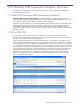
4. The Choose a destination screen is displayed. a. Select the Destination as Text File using the corresponding box. b. Select/specify the text file name using the File name box. c. Click on the Next button. Figure 7-2 DTS Import/Export Wizard – Choose a destination Screen 5. The Specify Table Copy or Query screen is displayed. Figure 7-3 DTS Import/Export Wizard – Specify Table Copy or Query Screen a.
b. Select the Use a query to specify the data to transfer option when you want to specify an SQL query result set data to be exported into the text file. Click on the Next button. The Type SQL Statement screen is displayed. You can either write an SQL query manually in the Query statement box, or use the Query Builder button to automatically build the query using a wizard. Click on the Parse button to check if the query is syntactically correct. To import an SQL script file, use the Browse button.
7. The Save, schedule, and replicate package screen is displayed. Use this screen to save the DTS package. You can also choose to replicate the data or schedule the package to be executed at a later time. Figure 7-6 DTS Import/Export Wizard – Save, schedule, and replicate package Screen Select the Run Immediately check box to start the process of exporting data to the specified .txt file immediately. In case you want to schedule the process, select the Schedule DTS package for later execution check box.
7-10-2 Using Windows BCP Command Line Utility The BCP command line utility is used for exporting the SQL data from an SQL Server to a text file or to other SQL Servers. Use the following command to export data from the ATM/TA database table to a .txt file. bcp queryout –c –U –S Where: is an SQL query. For example: Select * from .dbo.
7-11 User Not Able to View Default ATM/TA Web Page The problem may be occurring because of the following reasons: • Network Connection Outage For the clients to view ATM/TA web pages, the network connection with the Web Server should be up & running. Check if the network connection is working. • Web Server Problem You may need to (re)register the ASP.NET file extensions with the IIS Server. To do this, perform the following steps: a.
7-12 User Not Able to Connect to ATM/TA Database NOTE: If you get any database access related errors, the issues should be forwarded to the application/database administrators responsible for the ATM/TA product. The steps discussed here are for application/database administrator and not for the end user. If the users are not able to connect to the ATM/TA Database, check the SQL installation on the system. The problem may occur if SQL Server was installed in Windows Authentication Mode. Suggestions 1.
Figure 7-10 SQL Server Login Properties – New Login Dialog Box Click on the OK button. The new login will be displayed in the SQL Server Enterprise Manager. Figure 7-11 SQL Server Enterprise Manager 2. Check if the User ID/Password to Access the ATM/TA Database has been Changed. The ATM/TA application administrator has the information regarding the User-ID/Password being used by ATM/TA Application Server and the Web Server to access the ATM/TA database.
7-13 ATM/TA Web Page Not Displaying Any Data Figure 7-12 No Stats Available Message in ATM Web Page 7-14 User Unable to Install ATM Transaction Analyzer Services In case if the ATM/TA services do not get installed on your system after installing ATM Transaction Analyzer, you need to install them manually using command prompt.
7-15 User Unable to Create Views The user is getting the following validation error while creating new views. Figure 7-13 Server Error in ATM/TA Application Suggestions If tag in the web.config file (Drive:\Inetpub\wwwroot\ATMTA)is commented then please remove the comments, else you may receive errors while creating new views.
Appendix A Installation Information ATM/TA Database 1. User Name The user in whose name ATM/TA is registered. Example: John Smith 2. Company Name The company in whose name ATM/TA is registered. Example: ABC Inc. 3. Destination Location The directory on the workstation where ATM/TA Database is to be installed. 4. SQL Server Name The SQL Server where ATM/TA Database will be created or already exists. 5. SQL Server Port The port where the Microsoft SQL Server is listening. Default: 1433 6.
ATM/TA Application Server 1. User Name The user in whose name ATM/TA is registered. Example: John Smith 2. Company Name The company in whose name ATM/TA is registered. Example: ABC Inc. 3. Destination Location The directory on the workstation where ATM/TA Application Server is to be installed. 4. SQL Server Name The SQL Server where ATM/TA Database will be created or already exists. 5. SQL Server Port The port where the Microsoft SQL Server is listening. Default: 1433 6.
ATM/TA Web Server 1. User Name The user in whose name ATM/TA is registered. Example: John Smith 2. Company Name The company in whose name ATM/TA is registered. Example: ABC Inc. 3. Destination Location The directory on the workstation where ATM/TA Web Server is to be installed. 4. SQL Server Name The SQL Server where ATM/TA Database will be created or already exists. 5. System Name/IP Address The System Name/IP address where ATM/TA Application Server is installed. 6.
Appendix B TLFCONF File Parameters Parameter Description KEY License Key ADMINREC-PROCESS To Process admin transactions. YES|NO Default: NO COLL CollectorName ON|OFF to log events. Default: OFF PROD- BASENTUM Product base number for event logging. Default: 0 SSID SSID to use for event logging Default: TANDEM.
Description MAX-DATAFLOW-MSGS How Many Messages to avoid flood during long outage problem Default: 10 AUTO-RECV-TIME To enable recovery of data for specified duration of hours in online mode Default: 0 CUSTOM-DATA-LEN To specify the size in bytes of the customer specific extra tokens or data Default: 0 RECOVERY To enable/disable the recovery of missing transactions. ON|OFF Default: OFF SAF-CATCHUP-CONFIG To configure the catchup process.
Appendix C Database Mapping with TLF File This section provides a list of fields in the ATM database and the mapped fields in the TLF file. A sample USRTLFC file to populate transaction date/time and card number in user-defined fields from the TLF record is also described in this section. Table 3 Mapping of TLF File with Transaction Table Fields in ATM Database Fields in TLF File transID Description Unique number for a transaction. It can be treated as the primary key. recordType head.
Fields in ATM Database Fields in TLF File Description fromAccNum tlf_auth.from_acct.acct_num The account number of the ‘from’ account for the transaction. If the ‘from’ account is not needed or known, this field contains zeros. userFld1 tlf_auth.user_fld1 User-defined field. toAccNum tlf_auth.to_acct.acct_num The account number of the ‘to’ account for the transaction. If the ‘to’ account is not needed or known, this field contains zeros. multAccFlag tlf_auth.
Table 3 Mapping of TLF File with Transaction Table Fields in ATM Database Fields in TLF File Description fromHoldAmountImpact tlf_auth.refr.hld_amt_imp[0] An indicator used to define how the value in the AMT-ON-HLD field is impacted in the PBF account records. The first occurrence defines impacting on the ‘from’ account and the second occurrence defines impacting on the ‘to’ account. toAvailImpact tlf_auth.refr.
Fields in ATM Database Fields in TLF File Description origTransAmount tlf_auth.amt_1 The transaction amount requested. actualTransAmount tlf_auth.amt_2 For most reversal (0420) messages, this field contains the actual completion amount of the transaction. balAmount tlf_auth.amt_3 For most response (0210) messages, this field contains a balance amount. depBalCrAmount tlf_tlf_auth.dep_bal_cr The amount of credit given on a deposit entryTime The time the transaction entered the BASE24 system.
Table 4 Mapping of TLF File with Termbalancing Table Fields in ATM Database Fields in TLF File Description termRegionID head.regn_id The region ID associated with the terminal originating the transaction. adminTime term_setl.admin_tim The time the administrative transaction occurred. adminCode term_setl.admin_cde A code indicating a transaction type that involves increases and decreases of currency. This code also identifies whether the transaction was performed by a Device Handler or at a CRT.
Fields in ATM Database Fields in TLF File Description amountDep term_setl.amt_dep The unverified amount of the deposits accepted at the terminal since the last terminal balancing transaction numCmrclDep term_setl.num_cmrcl_dep The number of envelope deposits accepted in the Commercial (e.g., Securomatic) depository since the last terminal balancing transaction. amountCmrclDep term_setl.amt_cmrcl_dep The unverified amount of the deposits accepted in the commercial (e.g.
Table 5 Mapping of TLF File with TermCashAdj Table Fields in ATM Database Fields in TLF File transID Description Unique number for transaction. It can be treated as primary key. transactionTime head.dat_tim The date and time on which the record was logged. recordType head.rec_typ The type of TLF record logged. The value in this field is set by the process that creates the TLF record (i.e. Authorization, Device Handler or Settlement). authprocess head.
Table 6 Mapping of TLF File with Termsetelment Table Fields in TLF File transID Description Unique number for transaction. It can be treated as primary key. transactionTime head.dat_tim The date and time on which the record time was logged. recordType head.rec_typ The type of TLF record logged. The value in this field is set by the process that creates the TLF record (i.e. Authorization, Device Handler or Settlement). authprocess head.
Mapping of User-Defined Fields with TLF Fields ATM/TA provides user-defined fields which can be mapped to fields in the TLF record. Perform the following steps to map a user-defined field with TLF record. 1. Set the USER-TOKENS parameter in the TLFCONF file to YES. 2. Amend USRTLFC file on the ATMTA subvolume on the NonStop to populate the required TLF record in the user fields. 3. Stop the ATM/TA environment using the STOPTLF command. 4. Compile USRTLFC using the RUN ZTCMPTLF command. 5.
memcpy(fld1, tlfRec->u_tlf_auth_buf.tlf_auth_buf.auth.tran_dat.mm,2); fld1 += 2; *fld1 = '/'; fld1++; memcpy(fld1, tlfRec->u_tlf_auth_buf.tlf_auth_buf.auth.tran_dat.dd,2); fld1 += 2; *fld1 = ' '; fld1++; fld1 += 2; *fld1 = ':'; fld1++; memcpy(fld1, tlfRec->u_tlf_auth_buf.tlf_auth_buf.auth.tran_tim.mm,2); fld1 += 2; *fld1 = ':'; fld1++; memcpy(fld1, tlfRec->u_tlf_auth_buf.tlf_auth_buf.auth.tran_tim.
Appendix D Transaction Types This section lists the default Transaction Types along with their description.
Appendix E Reversal Codes Reversal Code Description 01 Time out 02 Command reject 03 Destination not available 08 Customer cancelled transaction 10 Hardware error 12 Original amount incorrect 13 ATM malfunction 14 Suspicious reversal override 15 Misdispense reversal override 16 Duplicate transaction 17 Reconciliation error 18 PLUS add cash withdrawal or advance 20 Suspect transaction 21 Message authentication code (MAC) failure 22 MAC key synchronization error 23 Message rep
Appendix F Response Codes This section lists the as along with their description.
Appendix G Threshold Expressions ATM/TA uses Boolean expressions to identify when a threshold is in violation. If the Boolean threshold expression evaluates to true, the threshold is considered to be in violation. Following are some examples of valid Boolean expressions: TotalTransactions > 100 This expression will cause the threshold to be violated for an entity when the total transactions exceed 100. TotalTransactions > 10 and PercentDenials > 5.
Field Name Field Type Description PercentEncryptErrors Integer Percent encryption errors PercentNetUnavailErrors Integer Percent net unavailable errors PercentUnableToAuthErrors Integer Percent unable to authenticate errors HighestResponseTime Integer Maximum response time RepeatedDenials Integer Consecutive denials Year Integer Year part of the current Stat time. Month Integer Month part of the current Stat time. Day Integer Day part of the current Stat time.
Appendix H Transaction Filter Expressions ATM/TA also supports using Boolean expressions to filter the transactions that are used to evaluate thresholds. If the Boolean expression evaluates to true, the transaction is added to the result set that will be used to evaluate the threshold, otherwise the transaction is ignored. Some examples of valid transaction filter Boolean expressions: cardIssuerFIID = “B021” This expression will enable only entities with Card issuer FIID equal to B021 to be displayed.
Field Name Field Type Description acquirerTermOwnerName String The name of the financial institution owning Terminal. acquirerTermCity String The City in which the Terminal located. acquirerTermState String The State in which the Terminal located. acquirerTermCountry String The Country in which the Terminal located. origTransSeqNum String origCrncyCode String Currency Code reversalReason String The reason for a reversal. PINOffset String The PIN offset value FrwdInstId.
Operator Reference Operator Description = Equal To < Less Than > Greater Than <= Less Than Or Equal To >= Greater Than Or Equal To != Not Equal To and Logical And or Logical Or Appendix H The following operators can be used within expressions: Appendix H 171
Appendix I Substitution Parameters ATM/TA provides the following substitution parameters that can be used for creating customized Alert text messages that will be generated for threshold violations. For example, to view Entity Name in the alert text on Alerts page, specify the alert text as Entity Name = %EntityName%. Parameter Description %EntityName% Display name of the entity %EntityType% Type of entity. %EntityCode% Entity ID specific to the entity name.
Description %Day% Day part of the current Stat time. %Hour% Hour part of the current Stat time. %Minute% Minute part of the current Stat time.
Appendix J Configuration Parameters ATMCommandControl Configuration Parameters Section: Data Source Configuration Parameter Description Data Source Name of the Database Server Initial Catalog Name of the database User ID Name of the database user Password Database password Windows Authentication Whether windows authentication mode is to be used or not Section: Operational Parameters Parameter Description MaxLogFileLen Log File Length size in Kb.
Description Log Error to Event Log Logs error messages to windows event viewer. The default value is false (0-false/1true). Default: 0 Maximum Number of Failure The Maximum Number Of Failure parameter shutdown the service after configured number of failures (in this case, NT service manager will not start the service).
Parameter Description Customer Data File Name Defines the path of the customer data configuration file. Default: CustomerMapFile.ini No Transaction Stat Enabled Enable statistics calculation when no Transactions logged in database. Default: 0 Max Num Request to Consider Stat Calculation Number of subsequent requests with no transactions to be considered to enable statistics calculation.
Description Notification Port The port on which ATMMON is listening. Log Debug info Enabled Enable logging of high level debugging information. Default: 1 Log All Errors Enabled Enable logging of all types of errors. If the value is set to 1, errors will be logged to ATMMON.log and also logged to Windows NT log. Default: 0 NOTE: This parameter is not applicable in the current release. Populate Violation Table Enabled Feed Violation table.
Parameter Description LogFile Name Name of the log file. Default: ATMStatGen.log dtFormatString Date format string for display purpose. Default: ddd MMM d yyyy HH:mm ignoredTransCodes Message Type to be ignored. reversalTransCodes The Reversal Message Type. Default: 0420,0412,0430 adjAppRespCodes Adjusted approval response codes. Default: 051,052,055,056,058,059,061,063,064 ApprovalResponseCodes Response codes for considering a transaction as approval.
Description LatencyWaitSecs Halts the statgen calculation for the specified time interval to get maximum possible data for the time gap of two collectors or nodes. Default: 30 MaxLatencyWaitEnableMins Halts the latency interval if the time gap between two collectors or nodes is more than the specified time in this parameter. Default: 30 WeeklyStatCalculationDay Specifies the weekday for calculating the weekly statistics.
Parameter Description execHour The hour (0-24) at which the maintain service should execute. Default: 0 execMin The min (0-59) at which the maintain service should execute. Default: 0 batchExecuteWaitTimeMs The amount of time to wait before batch file execution.
Description Processed File Path Places the successfully recovered files at the specified location. For example, ProcessedFilePath=C:\HP SST\RECOVERY\MOVED\ Error File Path Places all the files that are not recovered successfully at the specified location. For example, ErrorFilePath=C:\HP SST\RECOVERY\ERROR\ Action When Processed Specifies the action performed on the recovery files. The following actions are performed on the files: • 1: Move the files to the specified location (PROCESSED / ERROR).
Parameter Description StatsCalculationRetryMins Time interval in minutes after which the service will retry for missed stat calculation. Default: >=1 StatsCalculationStartTime(HH MM) Start time of stat calculation interval. Default: “0000” StatsCalculationEndTime(HH MM) Stop time of stat calculation interval. Default: “2359” MaxNumFailures The number of failures allowed. Zero (0) means infinite. Default: 0 FailureRestartTimeSecs Retries the failed operation after the configured time.
Description responsetimedisplayformat The number of digits to be displayed after the decimal in the Response time fields. For example a value of 5 will display the response time as 0.27777. If the value is 3, the response time will be displayed as 0.277. Default: 2 MonitorAddress IP address of the machine where Application Server is installed. MonitorPort The Port on which Web Service Communicates with the ATMMON Service.
Parameter Description EntityTypeSeperator The delimiter used to separate combined entity types. Default: “:” StatInterval The stat interval in minutes. Default: 5 QueryTimeoutSecs Maximum allowed time for the query execution on SQL Server. Default: 900 MaxNumOldLogFiles Maximum number of old log files. Default: “4” FailureRestartTimeSecs Retries the failed operation after the configured time. Default: 60 LogErrorsToEventLog Logs error messages to windows event viewer.
Description SET SERVICE NODE Specifies the HP NonStop node name. SET SERVICE HOST Specifies the IP address or domain name of the host. SET SERVICE IPADDR Specifies the IP address of the host. SET SERVICE PORT Specifies the port used for remote elink. SET SERVICE PROVIDER Specifies the types of service provided by the backend. The value is ATM. ADD SERVICE Add the above configuration parameters to the elink.
Appendix K ATM/TA EMS Event Details The following table lists the ATM/TA EMS events, considering PROD-BASENUM = 3000 in the TLFCONF file.
EMS Event ID* Text Message 32 3032 Failed to during #END registration, Error Detail= 37 3037 Failed during READX from , Last-File System Error= 40 3040 Failed to open . 41 3041 Failed during READX from '',Error Detail= 42 3042 Failed to open .
Internal Message ID EMS Event ID* Text Message 70 3070 safStatInterval SIGNALTIMEOUT ERROR 71 3071 TLFFILE '' closed. Records Read: , Records Processed: 72 3072 TLFFILE '' closed.
EMS Event ID* Text Message 109 3109 Nothing to recover offline .
Appendix L Elink EMS Event Details EMS Event ID Text Message 339 Successful on address(:) 340 Keep Alive option turned ON 344 ElinkUpOn::Remote Elink Connection Established 344 ClientRegFrom:: Client Connection Established 345 ElinkDownOn:: Client Connection Lost 345 ClientRegFrom::Remote Elink Connection Lost Appendix L 190
Appendix M Error Messages Service Errors Description ATMLOGGER Could not start service For some reason the Windows service manager could not start the service. Could not query service For some reason the Windows service manager could not query about the service. Could not open service For some reason the Windows service manager could not open handle about the service. Could not connect to the SCM service Could not connect to the Windows Service Control Manager.
Service Errors Description ATMSTATGEN Required parameter ConnectionInfo not set The parameters specified for database connection are not sufficient. Could not open database connection Could not connect to the database with the given DB connection info. No entity types defined in the database No entity types have been defined in the database. Could not convert code list. Resetting to default Exception occurred during reading codes (e.g.ReversalTransCodes,AdjAppRespCodes) specified in ini file.
Service Errors Description Could not uninstall service Unable to uninstall the service. ATMMAINTAI N Could not register service handler The application could not register itself as a service with the service handler. Init() : Couldn't load config file The application cannot load the configuration ini file POSMON is already running. Cannot start another instance Cannot start another instance of POSMON service as it is already running. Failures exceed allowable limit. Shutting down.
Service Errors Description Could not open logfilename The application fails to open the specified log file. DB Errors The errors that shoot from the database will be logged with the specific description.
Appendix N Implementing Dynamic Metric ATM/TA supports the feature of implementing dynamic metric to add user defined columns in the stats table. Follow the steps given below to add dynamic metric in ATM/TA: 1. Create a SQL function that defines the logic to evaluate the corresponding metric. 2.
Glossary Acquirer The acquirer is the organization which, under arrangement with and on behalf of an issuer, discharges the obligations owed by that issuer to the relevant cardholder when the cardholder undertakes a transaction via an access point owned/controlled by the acquirer. As a result, the acquirer engages in interchange activities with that issuer. Approvals Any transaction that is approved by the card holder’s bank (issuer).
Index $ATALG, 13 $ATALK, 13 $ATAnn, 13 $ATARD, 13 $ATMAN, 13 Elink, 14 ELKCONF, 13 Export to Excel, 109 F Features & Benefits, 10 Field Reference, 169 A H Acquirer, 54 Admin Privileges, 49 Alerts, 75 AT, 13 ATM/TA, 8 ATM/TA Application Server, 14 ATM/TA Backend Components, 13 ATM/TA Database, 14 ATM/TA Front-End Components, 14 ATM/TA Web Server, 14 ATMLoggerService, 122 ATMMaintain Service, 122 ATMMonitoring Service, 122 ATMStatgen Service, 122 ATMStatisticsAdjustment Service, 122 Authorizer, 54 HOSTT
Document Feedback Form We would appreciate your comments on the HP NonStop ATM Transaction Analyzer User and Installation Guide. After you have read the Guide and used the software, please take a few moments to complete this form and return it to appropriate HP product support service. Guide 1. The organization of the Guide makes it easy to locate topics quickly. Strongly Disagree 1 2. Strongly Agree 2 3 4 The appearance of the pages makes it easy to locate information quickly. Strongly Disagree 1 3.
The level of writing in this book is: Too Basic Just Right Too Technical (Please be specific.) 10. Do you have any other suggestions for improvement? Document Feedback Form 199 Document Feedback Form 9.