
Availability Guide for Problem Management

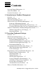
Contents
Availability Guide for Problem Management–125509
x
Figures
Figures
Figure 3-1. OMF General Status Screen 3-5
Figure 3-2. Sample Problem-Reporting Log 3-10
Figure 3-3. Sample Outage Log 3-12
Figure 3-4. Sample Problem-Solving Worksheet 3-15
Figure 4-1. System Message Analysis Chart Showing EMS Analyzer Data 4-6
Figure 4-2. Message Analysis Chart Showing EMS Analyzer Data 4-15
Figure 4-3. Sample System and Application Event Message Architecture 4-17
Figure 5-1. Pathway Object Diagram 5-3
Figure 5-2. Sample DSAP Summary Report 5-9
Figure 5-3. DETAIL for SQL/MP Tables, Indexes, and ENSCRIBE Files 5-11
Figure 5-4. DETAIL Format for NonStop SQL/MP Views 5-12
Figure 5-5. Object Monitoring With OMF 5-15
Figure 7-1. Continuous Operation of a NonStop System 7-2
Figure 8-1. The Disaster Planning Process 8-5
Figure 9-1. Flow of Event Messages 9-7
Figure 9-2. EMS Analyzer Architecture 9-11
Figure 9-3. Flow Map Architecture 9-13
Figure 9-4. Measure Architecture 9-15
Figure 9-5. NetBatch Architecture 9-16
Figure 9-6. NSX Architecture 9-19
Figure 9-7. The Role of the TMF Subsystem in Transaction Processing 9-22
Figure 9-8. VHS Architecture 9-26
Figure 9-9. OMF Architecture 9-27
Figure 9-10. ONS Subagent Components 9-30
Figure 9-11. Subsystem Control Facility (SCF) Architecture 9-33
Figure 9-12. TFDS Architecture 9-35