
AWAN 3883/4/5 Access Server Installation and Support Guide
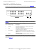
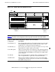
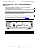
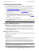
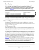
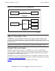
Table Of Contents
- What’s New in This Manual
- About This Manual
- 1 Introduction to the AWAN Access Server
- 2 Installing the AWAN Access Server
- 3 Maintaining the AWAN Access Server
- A Hardware Specifications
- B Modems
- C Adapter Hood Pinouts
- DB-9 PC Adapter Hood Pinouts (RS-232)
- DB-25 Terminal Adapter Hood Pinouts (RS-232)
- DB-25 Printer Adapter Hood Pinouts (RS-232)
- DB-25 Modem/Host Adapter Hood Pinouts (RS-232)
- DB-25 Host Adapter Hood Pinouts (Current Loop)
- DB-25 Terminal Adapter Hood Pinouts (Current Loop)
- DB-9 Host Adapter Hood Pinouts (Current Loop)
- Index
Introduction to the AWAN Access Server
AWAN 3883/4/5 Access Server Installation and Support Guide—424241-001
1-9
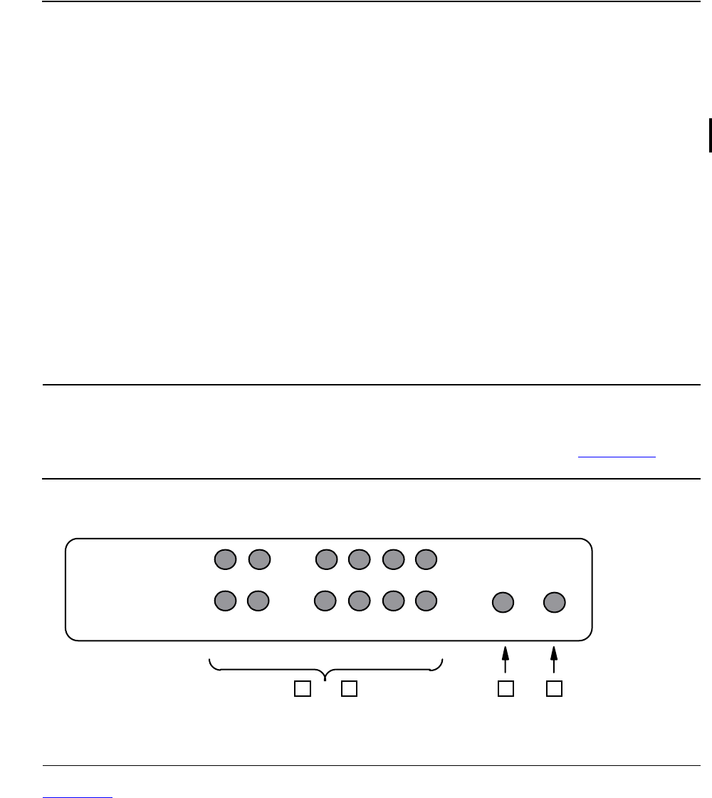
Model 3884 and 3884R Panel Indicators
Model 3884 and 3884R Panel Indicators
A partial view of the front panel of models 3884 and 3884R is shown in Figure 1-9.
Table 1-5
describes the LED indicators on the front panel of models 3884 and 3884R.
5 Factory
Configuration Button
This is a recessed push-switch that is used to reset the
AWAN access server to the factory default configuration at
power up time. Note:The Factory Configuration button might be
mislabeled “Reset”. The label should read “Factory Config”.
6 Console Port This is an RJ-45 receptacle used to connect a terminal or PC
used for boot utilities only.
7 Power Receptacle This is a grounded, three-wire receptacle for AC with an
integral fuse holder. It accepts the AC power cord supplied
with the AWAN access server.
8 Fuse Holder This is a fuse holder that uses an F1.6A 250 volt (5x20 mm)
fast-blow fuse. A compartment for a spare fuse is located in
the holder.
9 On/Off Switch This is a rocker switch for turning AC power on and off.
Press the topside side [|] of the switch to turn power on and
the bottom side [O] of the switch to turn power off.
Figure 1-9. Model 3884/3884R Front Panel
Table 1-4. Rear Panel Components (Models 3883-8, 3883-8R, 3883-16, and
3883-16R)
Item Component Description
015CDT .CDD
ACTIVITY
FAULT
PM2 PM1 LM4 LM3 LM2 LM1 PS
31 2
READY
4