
Data Transformation Engine Integration Flow Designer Reference Guide

Chapter 3 - Getting to Know the User Interface
Integration Flow Designer Reference Guide
30
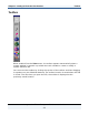
To use each tool, you must click the button and then click in the system window.
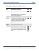
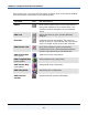
Each tool button is described in the following table.
Tool Name Tool Use This Tool To...
Select
Draw a box around one or more components in
the system definition file to select them. You
can then perform operations on the selected
group.
Add Text
Add a text block to your system definition
diagram.
Override
Override sources and targets. The source or
target of the first card selected will override the
source or target of the second card selected.
Add Pseudo Link
Draw links between system components.
Pseudo links serve a documentation purpose
and are represented by a red dotted line.
Add Source Map
(blue globe)
Add source map components.
Add Compiled Map
(green globe)
Add compiled map components.
Add Pseudo Map
(pink globe)
Add pseudo map components.
Add Subsystem
Add subsystem components.
Add External
System
Add an external system placeholder.