
Data Transformation Engine Integration Flow Designer Reference Guide


Chapter 3 - Getting to Know the User Interface Printing a System Definition Diagram
Integration Flow Designer Reference Guide
51
Printing a System Definition Diagram
In the IFD you can print a snapshot of the active system window.
To print system details
1 From the Navigator, select the system you want to print.
2 In the system window, arrange the system components to display how you
would like them to print. For example, double-click map source files to expand
or hide map components.
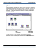
3 For best results, select File > Print Preview to view what will print, and then
click Print. Otherwise, select File > Print.
The Print dialog box appears.
4 Select a printer and click OK.
Using the Grid
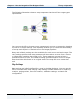
Components in a system diagram are positioned on a grid that can be viewed by
selecting Grid from the View menu or by clicking the grid icon on the tool bar.
To view the grid
1 From the tool bar, click to view or hide the grid.
You can also cause subsequent actions that add or move components to
position the components on the nearest grid point by enabling the snap to grid
mode. Enable or disable snap-to-grid mode by clicking
on the tool bar.
When snap-to-grid mode is enabled, existing components are not repositioned.
To cause new components to be aligned to a grid point
1 From the tool bar, click to enable/disable snap-to-grid mode.
When each new component is added, it will be positioned to its nearest
respective grid point until snap-to-grid mode is disabled.
To position existing components to the nearest grid point, select Align to Grid
from the Tools menu.