
Data Transformation Engine Intelligent Business Integration Reference Guide


Chapter 1 - Introduction Design Environment – Design Studio
Intelligent Business Integration Reference Guide
18
♦ Build and port entire systems with simple mouse-clicks
Note Refer to the Integration Flow Designer Reference Guide for more information.
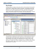
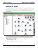
Graphical Design of Data Flow
Visual data flows are created to aid in the design of integration solutions. A
graphical palette enables you to produce system definition diagrams and navigate
easily among the Mercator Design Studio tools. Point-and-click techniques are
used to select which map and subsystem components to place in a specific
integration flow diagram.
Using the IFD, you can also define specific map settings that take effect at
runtime. Simply select the desired maps and the data flow between them is
automatically determined from the inputs and outputs. The Override tool in the
IFD toolbox can be used to modify the inputs and outputs to achieve the desired
data flows. These modifications do not affect the source map, which allows the
same map to be reused in multiple data flows.
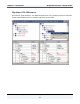
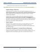
Logical Analysis
The IFD includes an Analyzer that checks your system definitions for logical
consistency to ensure they can be executed. The Analyzer detects any
inconsistencies you may have introduced in the definition while experimenting
with system models.
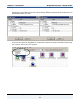
Configuration Management & Automated System Deployment
Once a system is designed, the IFD offers another benefit—saving time in
preparing a system for operation. One mouse-click builds and deploys all of the
integration objects and supporting data (such as lookup files and scripts).