
Data Transformation Engine Introduction to the Design Studio

Chapter 2 - Integration Flow Designer Integration Flow Designer Interface
Introduction to the Design Studio
18
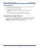
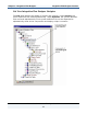
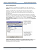
The name of the active system definition file and currently selected system appear
on the title bar. The system window of the Integration Flow Designer displays the
graphical system definition diagram and its map and subsystem components.
These components are initially collapsed when created in the system definition
diagrams. Map and subsystem components in the system definition diagram may
be expanded or collapsed. In the expanded view, details associated with a
component’s sources or targets are displayed. In addition, visual cues such as
tooltips for specific sources and targets help you to see key pieces of configuration
information. This visual approach of graphically displaying information is used
throughout the Integration Flow Designer interface.
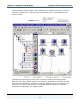
A system is an executable unit. A system may also be a component of another
system. This type of system is a subsystem component. A system can contain two
types of components: map and subsystem. A subsystem component is a reference
to another system that is already defined.
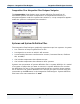
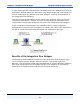
As with map components, the subsystem components are graphically displayed in
the system window of the Integration Flow Designer. You generate process control
information from these system definitions. The process control information is then
executed by Command Servers or Event Servers on other server platforms.