
Envoy ACP/XF Application Programming Manual


Features Common to Bit-Synchronous Protocols
EnvoyACP/XF Application Programming Manual–132179
B-2
Address Field
Zero-Bit Insertion (Bit-Stuffing)
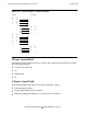
Your application must make provisions for zero-bit insertion or deletion. Zero-bit
insertion removes the risk that a sequence of six consecutive 1 bits (which could be
confused for a flag) might occur randomly within the other fields of the frame.
EnvoyACP/XF automatically inserts a zero bit immediately, after any sequence of five
consecutive one bits (Figure B-2
). The reverse procedure occurs when data is received: a
zero bit following five consecutive one bits is stripped from the input stream.
Zero-bit insertion and stripping affect only the bit stream between the starting and
ending flags. When the receiver detects a zero bit followed by five one bits, the receiver
inspects the next bit. If the next bit is a zero, the receiver passes the five consectuive one
bits as data and strips the trailing zero bit, thereby restoring the original data.
Abort
An abort procedure enables the station sending a frame to end the frame with a
notification to the receiving station to ignore the frame.
Aborting a frame is performed by transmitting at least 7, but less than 15, contiguous
1 bits (with no inserted 0s). The receipt of 7 contiguous 1 bits is interpreted as an abort,
and the controller discards the frame. The receipt of 15 or more contiguous 1 bits is
interpreted as an abort and an idle link state.
Address Field
The address field immediately follows the starting flag. This field contains the link-level
address of a secondary station or a combined station.
The standard address field is 8 bits (1 octet) in length. The specification for ADCCP
(ANSI Standard X3.66) also defines an extended address field of up to 4 consecutive
octets. EnvoyACP/XF provides for configuring extended addressing for all protocols;
however, the SDLC protocol standard does not support this capability.
Control Field
The address field is followed by the control field. The control field:
•
Contains data-link commands and responses
•
Specifies the frame format
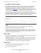
Figure B-2. Zero-Bit Insertion
original data –> 01100010 10000001 11110011 11110001 11111100
(including
control fields
and FCS)
after zero –> 01100010 10000001 111100011 111010001 111101100
bit insertion
(Note: Inserted zero(0)s appear in boldface type)