
Envoy ACP/XF Application Programming Manual


EnvoyACP/XF and the Application Task
EnvoyACP/XF Application Programming Manual–132179
1-18
Your Application and V.25 bis
! Enable DTR--Get ready to interact with the modem.
CONTROL fnum, 17, 1
if error then error_process; ! This should not occur
! An error returned at this time indicates that the modem is
! not in V.25 bis mode. A parameter value of "1" indicates
! that the DTE must wait for the indication from the modem.
Set V^25^ := true;
! The MCW is defined for the WRITE as follows:
! Bit 0 = 1: Set P/F bit
! Bit 1 = 1: Is a command or response UI-frame
! Bit 2 = 0: Information field is present in the frame
! Bits <3.7> = 0 : UI frame
v25 := true; ! in v25 mode flag
WHILE V^25 DO
begin
if get^v25^cmd then ! get v25 command
begin
write (fnum,v25^cmd); ! output to modem
if error then
call process^error;
end;
call read (fnum, buffer); ! read response from modem
if error then
begin
if error = 150 then ! out of v25 mode
v25 := false;
else call process^error;
end
else call process^message; ! process v25 message from modem
end; ! V.25 mode
CHANGELIST Fnum, 2,1 ! Remove "FF" station.
!Proceed in the mode for a normal switched line.
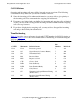
In the above example, an application for a primary SDLC station opens the line and
configures the line options (SETMODE 16). The DEFINELIST call includes the %HFF
address so that the station can accept frames from the V.25 bis modem while in V.25 bis
mode. The CONTROL 17,1 call enables DTR to wait for an indication from the modem.
If the modem indicates CTS, the DTE responds with RTS and the application posts a
WRITE to the modem (the MCW shows that a UI frame with information will be sent).
The information is the V.25 bis command. Once the UI frame has been sent, the
application posts a READ. If the READ completes with ERROR = 150, the application
removes the broadcast address (FF) from the polling list (CHANGELIST). The
application then can continue with data transmission in the specified protocol for that
line—for example, by sending a SNRM for the SDLC line.
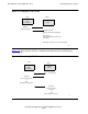
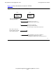
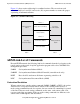
Figure 1-4
shows how the V.25 bis commands and indications are used during an
outgoing call.