
Envoy ACP/XF Application Programming Manual


EnvoyACP/XF and the Application Task
EnvoyACP/XF Application Programming Manual–132179
1-21
Your Application and V.25 bis
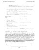
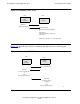
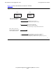
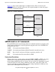
Figure 1-6 shows the interface circuits for V.25 bis.
Figure 1-6. Interface Circuits for V.25 bis
052
DTE
ServerNet
WAN
Concentrator
DCE
V.25 bis
Modem
Raises DTR on circuit 108
(indicating DTE READY)
Holds DSR low on circuit 107
(indicating V.25 bis protocol mode)
Raises CTS on circuit 106
(indicating CLEAR TO SEND)
when it is ready to accept commands from DTE
Raises RTS on circuit 105
(indicating READY TO SEND)
when sending commands
Raises DSR when a connection is established
(indicating end of V.25 bis protocol mode
and beginning of data transfer in specified line protocol)