Ethernet Adapter Installation and Support Guide Abstract This guide provides step-by-step procedures for installing, replacing and relocating Ethernet 4 ServerNet adapters on HP NonStop™ S-series servers. This guide is intended for anyone who installs or maintains E4SAs on NonStop S-series servers. Product Version N.A. Supported Release Version Updates (RVUs) This guide supports G06.20 and all subsequent G-series RVUs until otherwise indicated in a new edition.
Document History Part Number Product Version Published 140763 N.A. May 1998 420091-001 N.A. December 1998 425684-001 N.A. May 2000 425684-002 N.A. May 2003 425684-003 N.A.
Ethernet Adapter Installation and Support Guide Glossary Index Examples Figures Tables What’s New in This Guide vii Guide Information vii New and Changed Information vii HP Encourages Your Comments viii About This Guide ix Who Should Use This Guide ix What’s in This Guide ix Where to Get More Information x Notation Conventions xi 1.
3. Replacing an E4SA Contents 3.
4. Relocating an E4SA (continued) Contents 4. Relocating an E4SA (continued) Remove and Install the E4SA 4-22 Review Standard Operating Practices 4-22 Remove and Install the Adapter 4-24 Check the Installation of the E4SA 4-29 Resume Operations 4-31 Complete the Configuration Form 4-31 Add the E4SA Using SCF 4-34 A. E4SA Configuration Form B. Preparing an E4SA for PMF or IOMF CRU Replacement Safety and Compliance Glossary Index Examples Example 2-1. Example 3-1. Example 3-2. Example 3-3. Example 3-4.
Examples (continued) Contents Examples (continued) Example 3-20. Example 3-21. Example 3-22. Example 3-23. Example 3-24. Example 3-25. Example 3-26. Example 3-27. Example 3-28. Example 3-29. Example 3-30. Example 3-31. Example 3-32. Example 3-33. Example 3-34. Example 3-35. Example 3-36. Example 3-37. Example 4-1. Example 4-2. Example 4-3. Example 4-4. Example 4-5. Example 4-6. Example 4-7. Example 4-8. Example 4-9. Example 4-10. Example 4-11. Example 4-12. Example 4-13. Example 4-14. Example 4-15.
Examples (continued) Contents Examples (continued) Example 4-21. Example 4-22. Example 4-23. Example 4-24. Example 4-25. Example 4-26. SCF STOP SUBNET Command 4-17 SCF INFO ADAPTER Command 4-18 SCF INFO LIF Command 4-18 SCF STATUS LIF Command 4-19 SCF STATUS ADAPTER Command 4-20 SCF STATUS Commands 4-35 Figures Figure 1-1. Figure 1-2. Figure 2-1. Figure 2-2. Figure 2-3. Figure 2-4. Figure 2-5. Figure 2-6. Figure 2-7. Figure 2-8. Figure 2-9. Figure 3-1. Figure 3-2. Figure 3-3. Figure 3-4. Figure 3-5.
Figures (continued) Contents Figures (continued) Figure 4-9. Figure 4-10. Figure 4-11. E4SA Hardware Connection 4-28 E4SA External Indicators 4-30 Completed E4SAConfiguration Form 4-33 Tables Table i. Table 1-1. Table 2-1. Table 3-1. Table 3-2. Table 3-3. Table 4-1. Table 4-2. Table 4-3.
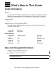
What’s New in This Guide Guide Information Ethernet Adapter Installation and Support Guide Abstract This guide provides step-by-step procedures for installing, replacing and relocating Ethernet 4 ServerNet adapters on HP NonStop™ S-series servers. This guide is intended for anyone who installs or maintains E4SAs on NonStop S-series servers. Product Version N.A. Supported Release Version Updates (RVUs) This guide supports G06.20 and all subsequent G-series RVUs until otherwise indicated in a new edition.
What’s New in This Guide • HP Encourages Your Comments Who Should Use This Guide has this new note: Note. This guide describes using TSM to perform E4SA procedures. As of G06.22 and later RVUs, the HP NonStop Open System Management (OSM) Interface replaces TSM as the system management tool of choice for NonStop S-series servers and is required to support new functionality in G06.22 and later RVUs. OSM provides the same functionality as TSM while overcoming limitations of TSM.
About This Guide This guide provides step-by-step procedures for installing, replacing, and relocating Ethernet 4 ServerNet adapters (E4SAs). This guide is intended for anyone who installs or maintains E4SAs on HP NonStop S-series servers. Who Should Use This Guide This guide is intended for anyone who installs or maintains E4SAs on NonStop S-series servers.
Where to Get More Information About This Guide Where to Get More Information Manuals describing the NonStop S-series servers are organized into several sets of manuals, which are fully described in the HP NonStop S-Series Planning and Configuration Guide.
Other Manuals About This Guide Other Manuals Depending on the tasks you are performing, you might also need the following manuals: • • • • • • LAN Configuration and Management Manual TCP/IP Configuration and Management Manual TCP/IP (Parallel Library) Configuration and Management Manual TCP/IPv6 Configuration and Management Manual IPX/SPX Configuration and Management Manual PAM Configuration and Management Manual Notation Conventions The following are notation conventions.
General Syntax Notation About This Guide each side of the list, or horizontally, enclosed in a pair of brackets and separated by vertical lines. For example: FC [ num ] [ -num] [ text] K [ X | D ] address-1 { } Braces. A group of items enclosed in braces is a list from which you are required to choose one item. The items in the list may be arranged either vertically, with aligned braces on each side of the list, or horizontally, enclosed in a pair of braces and separated by vertical lines.
Notation for Messages About This Guide Line Spacing. If the syntax of a command is too long to fit on a single line, each continuation line is indented three spaces and is separated from the preceding line by a blank line. This spacing distinguishes items in a continuation line from items in a vertical list of selections. For example: ALTER [ / OUT file-spec / ] CONTROLLER [ , attribute-spec ]... !i and !o.
Notation for Management Programming Interfaces About This Guide horizontally, enclosed in a pair of brackets and separated by vertical lines. For example: proc-name trapped [ in SQL | in SQL file system ] { } Braces. A group of items enclosed in braces is a list of all possible items that can be displayed, of which one is actually displayed.
Change Bar Notation About This Guide margin of changed portions of text, figures, tables, examples, and so on. Change bars highlight new or revised information. For example: The message types specified in the REPORT clause are different in the COBOL85 environment and the Common Run-Time Environment (CRE). The CRE has many new message types and some new message type codes for old message types. In the CRE, the message type SYSTEM includes all messages except LOGICAL-CLOSE and LOGICAL-OPEN.
Change Bar Notation About This Guide Ethernet Adapter Installation and Support Guide —425684-003 xvi
1 Introduction to the Ethernet 4 ServerNet Adapter (E4SA) This section provides an introduction to the Ethernet 4 ServerNet adapter (E4SA) for HP NonStop S-series servers.
Introduction to the Ethernet 4 ServerNet Adapter (E4SA) Overview of the E4SA Overview of the E4SA Note. E4SAs (including E4SA connections via S-series I/O enclosures) are not supported on NonStop BladeSystems. The Ethernet 4 ServerNet adapter (E4SA) is a ServerNet adapter that supports four Ethernet interfaces and communicates with multiple processors through its dual ServerNet interfaces to the ServerNet fabrics.
Introduction to the Ethernet 4 ServerNet Adapter (E4SA) External Connectors and Indicators Figure 1-1. Ethernet 4 ServerNet Adapter Power-On LED (green) Ejector Fault LED (amber) RJ-45 Connector Receive Data (green) Transmit Data (green) RX COL TX LNK ENET 1B Collision Detect (green) Link Integrity (green) SAC 1 RX COL TX LNK ENET 1A RX TX COL LNK ENET 0B SAC 0 RX COL TX LNK ENET 0A CDT 116.
Introduction to the Ethernet 4 ServerNet Adapter (E4SA) E4SA System Connections E4SA System Connections An E4SA has three primary, dual-ported system connections, as follows: • • • Data transfer interface (ServerNet) Diagnostics subsystem interface (Serial Maintenance Bus) Power interface Data Transfer Interface (ServerNet) The data transfer interface consists of ports for the X-fabric and Y-fabric. The ports attach to an internal router that connects to the two SACs on the adapter.
Introduction to the Ethernet 4 ServerNet Adapter (E4SA) • • • Power Interface • • Initializing the adapter for access to or from the ServerNet Controlling the adapter’s standard LEDs A serial EEPROM (SEEROM) that provides the following: • • • Hardware identification (part number and revision) Manufacturing tracking (serial) number MAC addresses CRU visual indicators Power control to the E4SA Power Interface The E4SA receives power through a shielded, high-density, metric connector module.
Introduction to the Ethernet 4 ServerNet Adapter (E4SA) Accessing an E4SA through the SLSA Subsystem access conventional TCP/IP, Parallel Library TCP/IP, or NonStop TCP/IPv6 subsystems: • • • • • The Expand subsystem, which interfaces to the TCP/IP subsystem to provide Expand-over-IP connections. Telserv and the File Transfer Protocol (FTP), which use the socket library to establish remote connections through the TCP/IP subsystem.
Introduction to the Ethernet 4 ServerNet Adapter (E4SA) Accessing an E4SA through the SLSA Subsystem Figure 1-2. How HP Subsystems and Utilities Use the SLSA Subsystem to Access an E4SA Processor User Applications File System Interface Socket Lib WAN IOP QIO Shared Memory Segment Expand WAN TCP/IP IPX/SPX PAM SLSA Processes LIF LIF LIF LIF LAN Drivers and Interrupt Handlers Y Fabric X Fabric E4SA Legend SLSA Subsystem CDT 001.
Introduction to the Ethernet 4 ServerNet Adapter (E4SA) Manufacturing Naming Conventions Manufacturing Naming Conventions HP manufacturing uses a naming convention for processes and devices that relates logical names to the physical location of devices. Table 1-1 describes the naming conventions used for SLSA subsystem processes and other processes and devices required by the SLSA subsystem. Table 1-1.
Manufacturing Naming Conventions Introduction to the Ethernet 4 ServerNet Adapter (E4SA) portid is the combination of the slot number and port number mapped in the following way Slot Number Port Number portid Slot Number Port Number portid 51 0 0 53 0 8 51 1 1 53 1 9 51 2 2 53 2 A 51 3 3 53 3 B 52 0 4 54 0 C 52 1 5 54 1 D 52 2 6 54 2 E 52 3 7 54 3 F Ethernet Adapter Installation and Support Guide—425684-003 1-9
Introduction to the Ethernet 4 ServerNet Adapter (E4SA) Manufacturing Naming Conventions Ethernet Adapter Installation and Support Guide—425684-003 1-10
2 Installing a New E4SA This section describes how to configure and install a new Ethernet 4 ServerNet adapter (E4SA) in an HP NonStop S-series system enclosure. An E4SA can be installed without shutting down the system. When a new system is shipped, HP manufacturing has already installed and configured two E4SAs. Additional E4SAs can be installed and configured by following the procedures outlined in this section. Note. As of G06.
Installing a New E4SA Prepare to Install a New E4SA Prepare to Install a New E4SA This section describes those tasks you should perform before installing or configuring a new E4SA. Table 2-1 summarizes the steps. Table 2-1. Preparation Checklist Step Description 1. Plan the Local Area Network (LAN). 2. Complete the Configuration Form. 3. Gather the Proper Tools. 4. Review Standard Operating Practices. Comments A sample form is provided. See Figure 2-1 on page 2-4.
Installing a New E4SA Complete the Configuration Form Complete the Configuration Form Complete an E4SA Configuration Form for each E4SA you are adding to your system. Figure 2-1 on page 2-4 shows an example of a completed Ethernet 4 ServerNet Adapter (E4SA) Configuration Form. When you add an adapter to a NonStop S-series system enclosure, you specify: • • • The name you want to use to identify the adapter; for example, E0153 for an Ethernet 4 ServerNet adapter in slot 53 of the first system enclosure.
Installing a New E4SA Complete the Configuration Form Figure 2-1. Completed E4SA Configuration Form Date Group SAC 1 Adapter Name: SAC Name: RX COL TX LNK IP Address: ENET 1B: PIF Name: \Case1 System Name Ethernet 4 ServerNet Adapter (E4SA) Configuration Form 01 Module 01 01 21 / Slot 00 / 53 192.168.2.093 E0153 E0153.1 E0153.1.B (0,1) SAC Access List: L01B LIF Name: ENET 1B SAC 1 SAC 1 Adapter Name: RX COL TX LNK IP Address: ENET 1A: SAC Name: 192.168.2.
Installing a New E4SA Complete the Configuration Form Figure 2-2.
Installing a New E4SA Complete the Configuration Form Figure 2-3 shows the E4SA installed in a system enclosure. Figure 2-3. E4SA Installed Ethernet 4 ServerNet Adapter (E4SA) Ejector Status LEDs RJ-45 Connector RX TX COL LNK ENET 1B SAC 1 RJ-45 Connector RX TX COL LNK ENET 1A RJ-45 Connector RX TX COL LNK ENET 0B SAC 0 RJ-45 Connector RX TX COL LNK ENET 0A CDT 663.
Installing a New E4SA Gather the Proper Tools Gather the Proper Tools You will need the following tools to install the adapter: Tool Used to. . . Electrostatic discharge (ESD) wriststrap with grounding clip Protect the adapter from damage caused by electrostatic discharge. Antistatic mat (recommended) Provide a static-free environment for removal and installation of an adapter. Flashlight Check the connectors for bent or broken pins. Note.
Installing a New E4SA Install the New E4SA Install the New E4SA You should perform the hardware installation first and then add the adapter using the Subsystem Control Facility (SCF). You can use SCF to add the adapter first and then insert the hardware. Whichever installation method you choose, the state of a logical interface (LIF) is not affected by the physical presence, or absence, of an adapter.
Installing a New E4SA Unpack and Install the New E4SA 6. Disconnect the grounding clip of your ESD wriststrap from the E4SA and connect it to an exposed, unpainted, metal surface on the service side of the system enclosure, such as the ventilation holes on the processor multifunction (PMF) or I/O multifunction (IOMF) CRU. See Figure 2-5, Grounding Clip, on page 2-10 or Figure 2-4, ESD Protected Environment. Figure 2-4.
Installing a New E4SA Unpack and Install the New E4SA Figure 2-5 shows how to connect the grounding clip to the ventilation holes on the PMF or IOMF CRU. Figure 2-5. Grounding Clip Processor Multifunction (PMF) CRU or I/O Multifunction (IOMF) CRU Grounding Clip To Grounding Wriststrap CDT 081.
Installing a New E4SA Unpack and Install the New E4SA Install the E4SA The following explains how to insert the E4SA into the system enclosure. 1. With the ejector on the E4SA in the full-open position (Figure 2-6 on page 2-11), grasp the E4SA by the ejector with one hand and support the bottom edge of the E4SA with the other hand (Figure 2-7 on page 2-12).
Installing a New E4SA Unpack and Install the New E4SA Figure 2-7. Installing a E4SA CDT 058.CDD 4. Disconnect the grounding clip of your ESD wriststrap from the enclosure. 5. Connect the RJ-45 connectors to the Ethernet ports on the E4SA. Connect the other ends of the cables to your Ethernet hub. Use the labels on the cables to make sure you connect each cable to the proper port and Ethernet hub.
Installing a New E4SA Unpack and Install the New E4SA Figure 2-8. E4SA Hardware Cable Connection Link Light RX COL TX LNK ENET 1B SAC 1 Link Light RX COL TX LNK ENET 1A Link Light RX COL TX LNK ENET 0B To LAN SAC 0 RJ 45 Connector Link Light RX TX COL LNK Ethernet Hub ENET 0A CDT 816.
Installing a New E4SA Check the Installation of the New E4SA Check the Installation of the New E4SA To check the installation of an E4SA: 1. Make sure that the power-on LED (green light) is on. Note. When the adapter is inserted, the fault LED (amber) remains on until the service processor has completed its start-up configuration. The fault LED also comes on when SLSA detects a POST failure. Figure 2-9 on page 2-15 shows the location of the power-on LED and fault LED. 2.
Installing a New E4SA Check the Installation of the New E4SA Figure 2-9. E4SA External Indicators Power-On LED (green) Ejector Fault LED (amber) RJ-45 Connector Receive Data (green) Transmit Data (green) RX COL TX LNK ENET 1B Collision Detect (green) Link Integrity (green) SAC 1 RX COL TX LNK ENET 1A RX TX COL LNK ENET 0B SAC 0 RX COL TX LNK ENET 0A CDT 116.
Installing a New E4SA Add and Start the E4SA Using SCF Add and Start the E4SA Using SCF Using the completed E4SA configuration form as a guide, use the SCF interface to the SLSA subsystem to add and start the newly installed E4SA. Note. Refer to the LAN Configuration and Management Manual for detailed information on the SLSA subsystem SCF commands. Adding and Starting the E4SA The following steps outline adding and starting the E4SA 1.
Installing a New E4SA Add and Start the E4SA Using SCF 5. Start the E4SA and its subordinate SAC and PIF objects by using either the TSM Service Application or the SLSA subsystem SCF START ADAPTER command with the SUB ALL option as shown in the following example. The SUB ALL option starts the ADAPTER object and its subordinate objects: ->START ADAPTER $ZZLAN.E1053, SUB ALL 6. Use the SLSA subsystem SCF STATUS commands to check that the adapter, SACs, PIFs, and LIFs have started as shown in Example 2-1.
Installing a New E4SA Add and Start the E4SA Using SCF 5. From the Setup menu, set up Timeframe, Source, or Subsystem criteria. Refer to the Operator Messages Manual for cause, effect, and recovery information for event messages. 2. Check the firmware version of the new E4SA. (When the AUTOFIRMUP attribute is set to ON, which is the default, the firmware file is automatically downloaded to the SAC when the SAC is started.
3 Replacing an E4SA This section describes how to perform online replacement of an Ethernet 4 ServerNet adapter (E4SA) in an HP NonStop S-series server. An E4SA can be replaced without shutting down the system. You might need to replace an E4SA if it has failed or partially failed. If POST fails and if there is an alarm generated by the TSM package on the SAC E4SA, the E4SA must be replaced. Note. As of G06.
Replacing an E4SA Prepare to Replace an E4SA Prepare to Replace an E4SA E4SAs can be installed in slots 53 and 54 of a processor enclosure and in slots 51, 52, 53, and 54 of an I/O enclosure. See Figure 3-3 on page 3-20. When no E4SA is installed in a slot, a ServerNet adapter filler panel occupies the empty slot. (Therefore, a ServerNet adapter filler panel can possibly occupy slots 53 and 54 of a processor enclosure or slots 51 through 54 of an I/O enclosure.
Replacing an E4SA Gather the Proper Tools Note.
Replacing an E4SA Print the E4SA Planning Worksheets Print the E4SA Planning Worksheets Print Figure 3-1 and Figure 3-2, the E4SA Planning Worksheets, and use them to record information about an Ethernet 4 ServerNet adapter (E4SA). Figure 3-1. E4SA Planning Worksheet (First Page) E4SA CRU Planning Worksheet Print this worksheet and use it to record information about an Ethernet 4 ServerNet adapter (E4SA) CRU.
Replacing an E4SA Print the E4SA Planning Worksheets Figure 3-2. E4SA Planning Worksheet (Continued) E4SA CRU Planning Worksheet (Continued) Expand-Over-IP Lines: Expand Line: ServerNet Wide Area Network (SWAN) Concentrators: SWAN: WAN Subsystem Input/Output Processes (IOPs): SWAN: WAN IOP: SWAN: WAN IOP: SWAN: WAN IOP: SWAN: WAN IOP: CDT041.
Replacing an E4SA Identify Any Communications Lines and ServerNet Wide Area Network (SWAN) Using the E4SA Identify Any Communications Lines and ServerNet Wide Area Network (SWAN) Using the E4SA The subsystems and utilities that use the SLSA subsystem to access an E4SA are illustrated in Figure 1-2 on page 1-7. The following procedure should help you identify the subsystems and utilities that are configured to use an E4SA.
Replacing an E4SA Identify Any Communications Lines and ServerNet Wide Area Network (SWAN) Using the E4SA 2. Determine the TCP/IP processes, subnets, and Internet Protocol (IP) addresses associated with the LIFs on the E4SA to be replaced. a. Use the SCF INFO SUBNET command: b. Scan the output of the command for each LIF you identified in Step 1 and then find the associated TCP/IP processes, subnets, and IP addresses. Make a note of this information on the E4SA Planning Worksheet (Continued) on page 3-5.
Replacing an E4SA Identify Any Communications Lines and ServerNet Wide Area Network (SWAN) Using the E4SA Example 3-3. SCF NAMES Command ->NAMES $ZZPAM PAM Names \SAMCAT.$ZZPAM PROCESS $TOK1 $ZZPAM LINE $TOK1 PORT $TOK1.#L1P0002 $TOK1.#L1P0004 MSAP $TOK1.#SNATR 4. Determine the PAM lines associated with the LIFs on the E4SA to be replaced. a. Use the SCF INFO LINE command for each PAM line you identified in Step 3: INFO LINE $line-name b. Scan the output for a LIF on the E4SA to be replaced.
Replacing an E4SA Identify Any Communications Lines and ServerNet Wide Area Network (SWAN) Using the E4SA Example 3-5. SCF NAMES SUBSYS Command ->NAMES SUBSYS $ZMGR IPXSPX Names SUBSYS \HIMA.$ZMGR SUBSYS $ZMGR PROCESS $ZNV0 SERVER $ZNV0.#SAP PROCESS $ZNV1 SERVER $ZNV1.#SAP 6. Determine the IPXPROTO processes associated with the LIFs on the E4SA to be replaced. a. Use the SCF INFO PROCESS command for each IPXPROTO process you identified in Step 5: INFO PROCESS $process-name b.
Replacing an E4SA Identify Any Communications Lines and ServerNet Wide Area Network (SWAN) Using the E4SA Example 3-7. SCF LISTDEV Command ->LISTDEV TYPE 63,0 LDev Name PPID 109 $IPYEA 3,9 159 $IPCORE 0,16 BPID 2,7 1,15 Type Rsize (63,0) 3 (63,0) 3 Pri 199 199 Program \COWBOY.$DATA00.T9057ADJ.LHOBJ \COWBOY.$DATA00.T9057ADJ.LHOBJ In this example, two Expand-over-IP lines (named $IPYEA and $IPCORE) are configured on the system.
Replacing an E4SA Identify Any Communications Lines and ServerNet Wide Area Network (SWAN) Using the E4SA 9. Identify the names of the SWAN concentrators configured on the system. Use the SCF NAMES ADAPTER command: NAMES ADAPTER $ZZWAN.#* Example 3-9 shows the output of this command. Example 3-9. SCF NAMES ADAPTER command ->NAMES ADAPTER $ZZWAN.#* WanMgr Names ADAPTER $ZZWAN.#* ADAPTER $ZZWAN.#S01 $ZZWAN.#S02 10.
Replacing an E4SA Redirect or Stop Any Customer Applications Using the E4SA 11. If you determined that a SWAN concentrator is connected to the E4SA CRU to be replaced, determine the names of the WAN subsystem IOPs configured to use that SWAN concentrator. a. Use the SCF INFO DEVICE command: INFO DEVICE $ZZWAN.#* b. Scan the output of the command for the SWAN concentrators you identified in Step 10. Make a note of the WAN subsystem IOPs that use the SWAN concentrators connected to the E4SA CRU.
Replacing an E4SA Stop the Communications Lines and SWAN Concentrator Lines Using an E4SA 1. Abort the communications lines. a. Use the SCF ABORT LINE command to stop a single line: ABORT LINE $line-name b. Use the SCF ABORT PATH command to stop the lines in an Expand multiline path: ABORT PATH $path-name 2. Verify that the lines are in the STOPPED state. a. Use the SCF STATUS LINE command for a single line: STATUS LINE $line-name Example 3-12 shows the output of this command.
Replacing an E4SA Stop the Communications Lines and SWAN Concentrator Lines Using an E4SA Example 3-14. SCF STATUS DEVICE Command ->STATUS DEVICE $ZZWAN.#LINE1 WAN Manager STATUS DEVICE for DEVICE \COWBOY.$ZZWAN.#LINE1 State :........ STOPPED LDEV number.... 110 PPIN........... 2 ,13 BPIN......... 3 ,14 5. Stop the SWAN concentrator. Use the SCF STOP ADAPTER command with the SUB ALL option. The SUB ALL option stops the ADAPTER object and its subordinate objects. STOP ADAPTER $ZZWAN.
Replacing an E4SA Stop the Communications Lines and SWAN Concentrator Lines Using an E4SA a. Use the SCF STATUS LINE command for a single line: STATUS LINE $line-name Example 3-16 shows the output of this command. Note that the line is in the STOPPED state. Example 3-16. SCF STATUS LINE Command ->STATUS LINE $LINE1 EXPAND Status LINE Name $LINE1 State STOPPED PPID 2, 10 BPID 3, 7 CIU-Path A ConMgr-LDEV 91 b.
Replacing an E4SA Stop the Communications Lines and SWAN Concentrator Lines Using an E4SA To Stop an IPXPROTO Process The following describes stopping an IPXPROTO process. 1. Stop the IPXPROTO process. a. If the IPXPROTO process is configured as a generic process, use the Kernel subsystem SCF ABORT PROCESS command: ABORT PROCESS $ZZKRN.#gpname b. If the IPXPROTO process is not configured as a generic process, use the SLSA subsystem SCF STOP PROCESS command: STOP PROCESS $process-name 2.
Replacing an E4SA Determine the Physical Location of the E4SA Example 3-20. SCF STATUS LINE Command ->STATUS LINE $TOK1 PAM Status LINE Name $TOK1 State STOPPED Primary CPU PIN 1 278 Backup CPU -1 PIN -1 Trace OFF To Stop a TCP/IP Subnet Caution. Make sure that the TACL session from which you are issuing SCF commands is not running on the subnet that you are about to stop. Note.
Replacing an E4SA Abort the E4SA Example 3-22. SCF INFO ADAPTER Command -> INFO ADAPTER $ZZLAN.E0153 SLSA Info ADAPTER Name $ZZLAN.E0153 Group 1 Module 1 Slot 53 Type E4SA Note. If Ethernet 4 ServerNet adapters (E4SA) are named using the HP Manufacturing naming convention, you can easily identify the physical location of the E4SA by its name as follows: $ZZLAN.Ecabid-slot where cabid is the two-digit number that identifies the enclosure and slot is the actual physical slot number in the enclosure.
Replacing an E4SA Label the Communications Cables Connected to the E4SA 3. Abort the E4SA object and its subordinate objects. You can use either SCF or the TSM Service Application to perform this step. a. Using SCF to Abort the Adapter: Use the SCF ABORT ADAPTER command with the SUB ALL option The SUB ALL option aborts the ADAPTER object and all its subordinate objects. ABORT ADAPTER $adapter-name, SUB ALL b. Using the TSM Service Application to Abort the Adapter: 1. Log on to the TSM Service Application.
Replacing an E4SA Label the Communications Cables Connected to the E4SA Figure 3-3. E4SA Slot Locations NonStop S-Series I/O Enclosure (Service Side) I/O enclosures can use slots 51 through 54 for E4SA CRUs NonStop S-Series Processor Enclosure (Service Side) Processor enclosures can only use slots 53 and 54 for E4SA CRUs 2. Tag each communications cable connected to the E4SA with a physical label, preferably at both ends.
Replacing an E4SA Replace the E4SA Replace the E4SA The following explains how to replace the E4SA. You must remove the adapter and then replace it. Table 3-2. Replacement Checklist Step Description 1. Review Standard Operating Practices 2. Remove the Adapter 3. Inspect the New E4SA and Backplane 4. Unpack and Install the New E4SA 5. Check the Installation of the New E4SA Note.
Replacing an E4SA Review Standard Operating Practices Figure 3-4. ESD Protected Environment System Enclosure (Appearance Side) ESD wriststrap clipped to door latch stud (or to any exposed, unpainted, metal surface on the enclosure frame.) ESD wriststrap with clip ESD floor mats ESD antistatic table mat. Mat should be connected to a soft ground (1 megohm min. to 10 megohm max.) Clip 15 inch straight ground cord to•screw screw on grounded outlet cover. CDT 693.
Replacing an E4SA Remove the Adapter Remove the Adapter The following describes how to remove the adapter. 1. Disconnect the communications cables from the E4SA. 2.
Replacing an E4SA Remove the Adapter Figure 3-6. Removing an E4SA CDT 059.CDD 5. Place the E4SA in an ESD protective bag and return it to its original packing container.
Replacing an E4SA Inspect the New E4SA and Backplane Inspect the New E4SA and Backplane To inspect an E4SA: Visually inspect the E4SA and the backplane connector for damage. Use a flashlight, if necessary, to check for bent or broken pins. You can damage pins by bumping or jamming the E4SA's shell against a surface, which can partially close the hole in the connector-pin socket. If the E4SA has a damaged connector-pin socket, do not install it. Caution.
Replacing an E4SA Unpack and Install the New E4SA Figure 3-5 on page 3-23 shows how to connect the grounding clip to the ventilation holes on the PMF or IOMF CRU. Install the E4SA The following explains how to insert the E4SA into the system enclosure. 1. With the ejector on the E4SA in the full-open position (Figure 3-7), grasp the E4SA by the ejector with one hand and support the bottom edge of the E4SA with the other hand as shown in Figure 3-8.
Replacing an E4SA Unpack and Install the New E4SA Figure 3-8. Installing an E4SA CDT 058.CDD 3. Press the blue-green tab on the E4SA ejector and latch the ejector to seat the E4SA against the backplane. 4. Disconnect the grounding clip of your ESD wriststrap from the enclosure. 5. Connect the RJ-45 connectors to the Ethernet ports on the E4SA. Connect the other ends of the cables to your Ethernet hub. Use the labels on the cables to make sure you connect each cable to the proper port and Ethernet hub.
Replacing an E4SA Unpack and Install the New E4SA Figure 3-9. E4SA Hardware Connection Link Light RX COL TX LNK ENET 1B SAC 1 Link Light RX COL TX LNK ENET 1A Link Light RX COL TX LNK ENET 0B To LAN SAC 0 RJ 45 Connector Link Light RX TX COL LNK Ethernet Hub ENET 0A CDT 816.
Replacing an E4SA Check the Installation of the New E4SA Check the Installation of the New E4SA To check the installation of an E4SA: 1. Make sure that the power-on LED (green light) is on. Note. When the adapter is inserted, the fault LED (amber) remains on until the service processor has completed its start-up configuration. The fault LED also comes on when SLSA detects a POST failure. Figure 3-10 on page 3-30 shows the location of the power-on LED and fault LED. 2.
Replacing an E4SA Check the Installation of the New E4SA Figure 3-10. E4SA External Indicators Power-On LED (green) Ejector Fault LED (amber) RJ-45 Connector Receive Data (green) Transmit Data (green) RX COL TX LNK ENET 1B Collision Detect (green) Link Integrity (green) SAC 1 RX COL TX LNK ENET 1A RX TX COL LNK ENET 0B SAC 0 RX COL TX LNK ENET 0A CDT 116.
Replacing an E4SA Resume Operations Resume Operations The following describes starting the new E4SA. Table 3-3. Resuming Operations Checklist Step Description 1. Start the New E4SA 2. Restart the Communications Lines 3. Verify that the Communications Lines are Restarted 4. Resume Customer Applications Comments See Note below. Note. You need to perform this step if you stopped communications lines or if an IPXPROTO process was using the E4SA CRU that was replaced.
Replacing an E4SA Start the New E4SA Verify that Objects Are in the STARTED State Use the following SCF STATUS commands: 1. Verify that the E4SA ADAPTER object is in the STARTED state. Use the SCF STATUS ADAPTER command: STATUS ADAPTER $ZZLAN.adapter-name.* Example 3-25 shows the output of the SCF STATUS ADAPTER command. Note that the ADAPTER is in the STARTED state. Example 3-25. SCF STATUS ADAPTER command ->STATUS ADAPTER $ZZLAN.E0153 SLSA Status ADAPTER Name $ZZLAN.E0153.0 $ZZLAN.E0153.
Replacing an E4SA Start the New E4SA Example 3-27. SCF STATUS PIF command ->STATUS PIF $ZZLAN.E0153.* SLSA Status PIF Name $ZZLAN.E0153.0.A $ZZLAN.E0153.0.B $ZZLAN.E0153.1.A $ZZLAN.E0153.1.B State STARTED STARTED STARTED STARTED 4. Start the logical interfaces (LIFs). Use the SCF START LIF command for each LIF: START LIF $ZZLAN.lif-name START LIF $ZZLAN.lif-name START LIF $ZZLAN.lif-name START LIF $ZZLAN.lif-name 5. Verify that the LIFs are in the STARTED state.
Replacing an E4SA Restart the Communications Lines 3. Type the NonStop Kernel user name and password. 4. Click OK. 5. From the Setup menu, set up Timeframe, Source, or Subsystem criteria. Refer to the Operator Messages Manual for cause, effect, and recovery information for event messages. 2. Check the firmware version of the new E4SA. (When the AUTOFIRMUP attribute is set to ON, which is the default, the firmware file is automatically downloaded to the SAC when the SAC is started.
Replacing an E4SA Verify that the Communications Lines are Restarted Use the SCF START LINE command with the SUB ALL option. The SUB ALL option starts the LINE object and its subordinate objects. START LINE $line-name, SUB ALL 4. Start an Expand-over-IP line. a. Start the WAN subsystem input/output process (IOP). Use the SCF START DEVICE command: START DEVICE $ZZWAN.#device-name b. Start the line(s). 1. Use the SCF START LINE command to start a single line: START LINE $line-name 2.
Replacing an E4SA Verify that the Communications Lines are Restarted 1. Verify that the TCP/IP subnets are started. Note. To verify TCP/IP subnets that are configured using Parallel Library TCP/IP, refer to the TCP/IP (Parallel Library) Configuration and Management Manual. To verify TCP/IP subnets that are configured using NonStop TCP/IPv6, refer to the TCP/IPv6 Configuration and Management Manual. Use the SCF STATUS SUBNET command: STATUS SUBNET $tcpip-process-name.
Replacing an E4SA Verify that the Communications Lines are Restarted 4. Verify that an Expand-over-IP line is started: a. Verify that the WAN subsystem IOP is in the STARTED state. Use the SCF STATUS DEVICE command: STATUS DEVICE $ZZWAN.#device-name b. Verify that the line is in the STARTED state. 1. Use the SCF STATUS LINE command for a single line: STATUS LINE $line-name Example 3-32 shows the output of this command. Note that the line is in the STARTED state. Example 3-32.
Replacing an E4SA Verify that the Communications Lines are Restarted Example 3-34 on page 3-38 shows the output of this command. Note that the ADAPTER, SERVER, PATH, and TASK objects are in the STARTED state. Note. Detailed information for only one communications line interface processor (CLIP) is included in the display. Example 3-34. SCF STATUS ADAPTER Command ->STATUS ADAPTER $ZZWAN.#S01, SUB ALL WAN Manager STATUS ADAPTER for ADAPTER \COWBOY.$ZZWAN.#S01 State....... STARTED Number of clips.
Replacing an E4SA Verify that the Communications Lines are Restarted Example 3-35. SCF STATUS DEVICE Command ->STATUS DEVICE $ZZWAN.#LINE1 WAN Manager STATUS DEVICE for DEVICE \COWBOY.$ZZWAN.#LINE1 State :........ STARTED LDEV number.... 110 PPIN........... 2 ,13 BPIN......... 3 ,14 c. Verify that the lines are in the STARTED state. 1. Use the SCF STATUS LINE command for a single line: STATUS LINE $line-name Example 3-36 shows the output of these commands. Note that the line is in the STARTED state.
Replacing an E4SA Resume Customer Applications 5. From the Setup menu, select either Timeframe, Source, or Subsystem criteria, or all three. Refer to the Operator Messages Manual for cause, effect, and recovery information for event messages. Resume Customer Applications To resume customer applications: 1. Perform any actions necessary to resume customer applications. Note. The actions required to perform this step depend on the customer's application. 2.
4 Relocating an E4SA This section describes how to relocate a Ethernet 4 ServerNet adapter (E4SA) that has been previously installed in an HP NonStop S-series system enclosure. An E4SA can be relocated without shutting down the system. Note. As of G06.22 and later RVUs, the HP NonStop Open System Management (OSM) Interface replaces TSM as the system management tool of choice for NonStop systems. For instructions on using OSM or migrating to OSM, refer to the OSM documentation for your RVU. Caution.
Relocating an E4SA Prepare to Relocate an E4SA Prepare to Relocate an E4SA E4SAs can be installed in slots 53 and 54 of a processor enclosure and in slots 51, 52, 53, and 54 of an I/O enclosure. See Figure 4-3 on page 4-21. When no E4SA is installed in a slot, a ServerNet adapter filler panel occupies the empty slot. (Therefore, a ServerNet adapter filler panel can possibly occupy slots 53 and 54 of a processor enclosure or slots 51 through 54 of an I/O enclosure.
Relocating an E4SA Gather the Proper Tools Gather the Proper Tools You will need the following tools to replace an adapter: Tool Used to. . . Electrostatic discharge (ESD) wriststrap with grounding clip Protect the adapter from damage caused by electrostatic discharge. Antistatic mat (recommended) Provide a static-free environment for removal and installation of an adapter. Flashlight Check the connectors for bent or broken pins. Note.
Relocating an E4SA Print the E4SA Planning Worksheets Print the E4SA Planning Worksheets Print Figure 4-1 and Figure 4-2, the E4SA Planning Worksheets, and use them to record information about an Ethernet 4 ServerNet adapter (E4SA). Figure 4-1. E4SA Planning Worksheet (First Page) E4SA CRU Planning Worksheet Print this worksheet and use it to record information about an Ethernet 4 ServerNet adapter (E4SA) CRU.
Relocating an E4SA Print the E4SA Planning Worksheets Figure 4-2. E4SA Planning Worksheet (Continued) E4SA CRU Planning Worksheet (Continued) Expand-Over-IP Lines: Expand Line: ServerNet Wide Area Network (SWAN) Concentrators: SWAN: WAN Subsystem Input/Output Processes (IOPs): SWAN: WAN IOP: SWAN: WAN IOP: SWAN: WAN IOP: SWAN: WAN IOP: CDT041.
Relocating an E4SA Identify Any Communications Lines and ServerNet Wide Area Network (SWAN) Using the E4SA Identify Any Communications Lines and ServerNet Wide Area Network (SWAN) Using the E4SA The subsystems and utilities that use the SLSA subsystem to access an E4SA are illustrated in Figure 1-2 on page 1-7. The following procedure should help you identify the subsystems and utilities that are configured to use an E4SA.
Relocating an E4SA Identify Any Communications Lines and ServerNet Wide Area Network (SWAN) Using the E4SA 2. Determine the TCP/IP processes, subnets, and Internet Protocol (IP) addresses associated with the LIFs on the E4SA to be replaced. a. Use the SCF INFO SUBNET command: INFO SUBNET $*.* b. Scan the output of the command for each LIF you identified in Step 1 and then find the associated TCP/IP processes, subnets, and IP addresses.
Relocating an E4SA Identify Any Communications Lines and ServerNet Wide Area Network (SWAN) Using the E4SA Example 4-3. SCF NAMES Command ->NAMES $ZZPAM PAM Names \SAMCAT.$ZZPAM PROCESS $TOK1 $ZZPAM LINE $TOK1 PORT $TOK1.#L1P0002 $TOK1.#L1P0004 MSAP $TOK1.#SNATR 4. Determine the PAM lines associated with the LIFs on the E4SA to be replaced. a. Use the SCF INFO LINE command for each PAM line you identified in Step 3: INFO LINE $line-name b. Scan the output for a LIF on the E4SA to be replaced.
Relocating an E4SA Identify Any Communications Lines and ServerNet Wide Area Network (SWAN) Using the E4SA Example 4-5. SCF NAMES SUBSYS Command ->NAMES SUBSYS $ZMGR IPXSPX Names SUBSYS \HIMA.$ZMGR SUBSYS $ZMGR PROCESS $ZNV0 SERVER $ZNV0.#SAP PROCESS $ZNV1 SERVER $ZNV1.#SAP 6. Determine the IPXPROTO processes associated with the LIFs on the E4SA to be replaced. a. Use the SCF INFO PROCESS command for each IPXPROTO process you identified in Step 5: INFO PROCESS $process-name b.
Relocating an E4SA Identify Any Communications Lines and ServerNet Wide Area Network (SWAN) Using the E4SA Example 4-7. SCF LISTDEV Command ->LISTDEV TYPE 63,0 LDev Name PPID 109 $IPYEA 3,9 159 $IPCORE 0,16 BPID 2,7 1,15 Type Rsize (63,0) 3 (63,0) 3 Pri 199 199 Program \COWBOY.$DATA00.T9057ADJ.LHOBJ \COWBOY.$DATA00.T9057ADJ.LHOBJ In this example, two Expand-over-IP lines (named $IPYEA and $IPCORE) are configured on the system.
Relocating an E4SA Identify Any Communications Lines and ServerNet Wide Area Network (SWAN) Using the E4SA 9. Identify the names of the SWAN concentrators configured on the system. Use the SCF NAMES ADAPTER command: NAMES ADAPTER $ZZWAN.#* Example 4-9 shows the output of this command. Example 4-9. SCF NAMES ADAPTER command ->NAMES ADAPTER $ZZWAN.#* WanMgr Names ADAPTER $ZZWAN.#* ADAPTER $ZZWAN.#S01 $ZZWAN.#S02 10.
Relocating an E4SA Redirect or Stop Any Customer Applications Using the E4SA 11. If you determined that a SWAN concentrator is connected to the E4SA CRU to be replaced, determine the names of the WAN subsystem IOPs configured to use that SWAN concentrator. a. Use the SCF INFO DEVICE command: INFO DEVICE $ZZWAN.#* b. Scan the output of the command for the SWAN concentrators you identified in Step 10. Make a note of the WAN subsystem IOPs that use the SWAN concentrators connected to the E4SA CRU.
Relocating an E4SA Stop the Communications Lines and SWAN Concentrator Lines Using an E4SA 1. Abort the communications lines. a. Use the SCF ABORT LINE command to stop a single line: ABORT LINE $line-name b. Use the SCF ABORT PATH command to stop the lines in an Expand multiline path: ABORT PATH $path-name 2. Verify that the lines are in the STOPPED state. a. Use the SCF STATUS LINE command for a single line: STATUS LINE $line-name Example 4-12 shows the output of this command.
Relocating an E4SA Stop the Communications Lines and SWAN Concentrator Lines Using an E4SA Example 4-14. SCF STATUS DEVICE Command ->STATUS DEVICE $ZZWAN.#LINE1 WAN Manager STATUS DEVICE for DEVICE \COWBOY.$ZZWAN.#LINE1 State :........ STOPPED LDEV number.... 110 PPIN........... 2 ,13 BPIN......... 3 ,14 5. Stop the SWAN concentrator. Use the SCF STOP ADAPTER command with the SUB ALL option. The SUB ALL option stops the ADAPTER object and its subordinate objects. STOP ADAPTER $ZZWAN.
Relocating an E4SA Stop the Communications Lines and SWAN Concentrator Lines Using an E4SA a. Use the SCF STATUS LINE command for a single line: STATUS LINE $line-name Example 4-16 shows the output of this command. Note that the line is in the STOPPED state. Example 4-16. SCF STATUS LINE Command ->STATUS LINE $LINE1 EXPAND Status LINE Name $LINE1 State STOPPED PPID 2, 10 BPID 3, 7 CIU-Path A ConMgr-LDEV 91 b.
Relocating an E4SA Stop the Communications Lines and SWAN Concentrator Lines Using an E4SA To Stop an IPXPROTO Process The following describes stopping an IPXPROTO process. 1. Stop the IPXPROTO process. a. If the IPXPROTO process is configured as a generic process, use the Kernel subsystem SCF ABORT PROCESS command: ABORT PROCESS $ZZKRN.#gpname b. If the IPXPROTO process is not configured as a generic process, use the SLSA subsystem SCF STOP PROCESS command: STOP PROCESS $process-name 2.
Relocating an E4SA Determine the Physical Location of the E4SA Example 4-20. SCF STATUS LINE Command ->STATUS LINE $TOK1 PAM Status LINE Name $TOK1 State STOPPED Primary CPU PIN 1 278 Backup CPU -1 PIN -1 Trace OFF To Stop a TCP/IP Subnet Caution. Make sure that the TACL session from which you are issuing SCF commands is not running on the subnet that you are about to stop. Note.
Relocating an E4SA Stop the E4SA 2. Scan the output of the command for the group, module, and slot location. Example 4-22. SCF INFO ADAPTER Command -> INFO ADAPTER $ZZLAN.E0153 SLSA Info ADAPTER Name $ZZLAN.E0153 Group 1 Module 1 Slot 53 Type E4SA Note. If Ethernet 4 ServerNet adapters (E4SA) are named using the HP Manufacturing naming convention, you can easily identify the physical location of the E4SA by its name as follows: $ZZLAN.
Relocating an E4SA Stop the E4SA 2. Stop access to the logical interfaces (LIFs) associated with the Ethernet 4 ServerNet adapter (E4SA) to be relocated. Use the SCF STOP LIF command for each LIF: STOP LIF $ZZLAN.lif-name STOP LIF $ZZLAN.lif-name STOP LIF $ZZLAN.lif-name STOP LIF $ZZLAN.lif-name If you receive a message that the LIF clients are still active, use the SCF ABORT LIF command to remove the LIFs. 3. Verify that the LIFs associated with the E4SA to be relocated are in the STOPPED state.
Relocating an E4SA Locate the New Slot 5. Verify that the E4SA ADAPTER object is in the STOPPED state. Use the SCF STATUS ADAPTER command: STATUS ADAPTER $adapter-name Example 4-25 shows the output of this command. Note that the ADAPTER (E0153) is in the STOPPED state. Example 4-25. SCF STATUS ADAPTER Command ->STATUS ADAPTER $ZZLAN.E0153 SLSA Status ADAPTER Name $ZZLAN.
Relocating an E4SA Label the Communications Cables Connected to the E4SA Figure 4-3. E4SA Slot Locations NonStop S-Series I/O Enclosure (Service Side) I/O enclosures can use slots 51 through 54 for E4SA CRUs NonStop S-Series Processor Enclosure (Service Side) Processor enclosures can only use slots 53 and 54 for E4SA CRUs 2. Tag each communications cable connected to the E4SA with a physical label, preferably at both ends.
Relocating an E4SA Remove and Install the E4SA Remove and Install the E4SA The following explains how to remove the E4SA that will be relocated to a new slot. Table 4-2. Replacement Checklist Step Description 1. Review Standard Operating Practices 2. Remove and Install the Adapter 3. Check the Installation of the E4SA Note. Whenever you handle an Ethernet 4 ServerNet adapter (E4SA), you should follow standard operating practices to avoid damage to the equipment.
Relocating an E4SA Review Standard Operating Practices Figure 4-4. ESD Protected Environment System Enclosure (Appearance Side) ESD wriststrap clipped to door latch stud (or to any exposed, unpainted, metal surface on the enclosure frame.) ESD wriststrap with clip ESD floor mats ESD antistatic table mat. Mat should be connected to a soft ground (1 megohm min. to 10 megohm max.) Clip 15 inch straight ground cord to•screw screw on grounded outlet cover. CDT 693.
Relocating an E4SA Remove and Install the Adapter Remove and Install the Adapter The following steps describe how to remove an E4SA and then install it in a new location. 1. Disconnect the communications cables from the E4SA. 2.
Relocating an E4SA Remove and Install the Adapter Figure 4-6 shows how to pull the E4SA out of the slot. Figure 4-6. Removing an E4SA CDT 059.CDD 5. Move the E4SA to the new slot. a. Disconnect the grounding clip of your ESD wriststrap from the system enclosure, and connect it to an exposed, unpainted metal surface on the E4SA. b. Grasp the E4SA by its ejector with one hand, and support the bottom edge of the E4SA with the other hand. Carry the E4SA to the slot where it is to be installed. Note.
Relocating an E4SA Remove and Install the Adapter 6. Disconnect the grounding clip of your ESD wriststrap from the E4SA and connect it to an exposed, unpainted, metal surface on the service side of the system enclosure, such as the ventilation holes on the processor multifunction (PMF) or I/O multifunction (IOMF) CRU. Figure 4-5 on page 4-24 shows how to connect the grounding clip to the ventilation holes on the PMF or IOMF CRU. 7.
Relocating an E4SA Remove and Install the Adapter Figure 4-8. Installing an E4SA CDT 058.CDD 9. Press the blue-green tab on the E4SA ejector and latch the ejector to seat the E4SA against the backplane. 10. Disconnect the grounding clip of your ESD wriststrap from the enclosure. 11. Install the double-high filler panel in the slot left vacant by the E4SA you moved. 12. Connect the RJ-45 connectors to the Ethernet ports on the E4SA. Connect the other ends of the cables to your Ethernet hub.
Relocating an E4SA Remove and Install the Adapter Figure 4-9. E4SA Hardware Connection Link Light RX COL TX LNK ENET 1B SAC 1 Link Light RX COL TX LNK ENET 1A Link Light RX COL TX LNK ENET 0B To LAN SAC 0 RJ 45 Connector Link Light RX TX COL LNK Ethernet Hub ENET 0A CDT 816.
Relocating an E4SA Check the Installation of the E4SA Check the Installation of the E4SA To check the installation of an E4SA: 1. Make sure that the power-on LED (green light) is on. Note. When the adapter is inserted, the fault LED (amber) remains on until the service processor has completed its start-up configuration. The fault LED also comes on when SLSA detects a POST failure. Figure 4-10 on page 4-30 shows the location of the power-on LED and fault LED. 2.
Relocating an E4SA Check the Installation of the E4SA Figure 4-10. E4SA External Indicators Power-On LED (green) Ejector Fault LED (amber) RJ-45 Connector Receive Data (green) Transmit Data (green) RX COL TX LNK ENET 1B Collision Detect (green) Link Integrity (green) SAC 1 RX COL TX LNK ENET 1A RX TX COL LNK ENET 0B SAC 0 RX COL TX LNK ENET 0A CDT 116.
Relocating an E4SA Resume Operations Resume Operations The following describes starting the relocated E4SA. Table 4-3. Resuming Operations Checklist Step Description 1. Complete the Configuration Form 2. Add the E4SA Using SCF Complete the Configuration Form Complete a new configuration form for the relocated E4SA. Figure 4-11 on page 4-33 shows an example of a completed Ethernet 4 ServerNet Adapter (E4SA) Configuration Form.
Relocating an E4SA • • • • • Complete the Configuration Form Enter the SAC name. Enter the numbers of the processors that will have access to the SAC in the SAC Access List field. The first processor listed is the preferred processor. Enter the PIF name associated with the SAC in the PIF Name field. Enter the LIF name associated with each PIF in the LIF Name field. When you have completed this form, enter today’s date in the Date field.
Relocating an E4SA Complete the Configuration Form Figure 4-11. Completed E4SAConfiguration Form Date Group SAC 1 Adapter Name: SAC Name: RX COL TX LNK IP Address: ENET 1B: PIF Name: \Case1 System Name Ethernet 4 ServerNet Adapter (E4SA) Configuration Form 01 Module 01 01 21 / Slot 00 / 53 192.168.2.093 E0153 E0153.1 E0153.1.B (0,1) SAC Access List: L01B LIF Name: ENET 1B SAC 1 SAC 1 Adapter Name: RX COL TX LNK IP Address: ENET 1A: SAC Name: 192.168.2.
Relocating an E4SA Add the E4SA Using SCF Add the E4SA Using SCF Using the completed E4SA configuration form as a guide, use the SCF interface to the SLSA subsystem to add the newly installed E4SA. Note. Refer to the LAN Configuration and Management Manual for detailed information on the SLSA subsystem SCF commands. The following steps outline adding and starting the relocated E4SA 1. Add the E4SA by using the SLSA subsystem SCF ADD ADAPTER command as follows:.
Relocating an E4SA Add the E4SA Using SCF in the following example. The SUB ALL option starts the ADAPTER object and its subordinate objects: ->START ADAPTER $ZZLAN.E1053, SUB ALL Note. You can also use the TSM Service Application to start an adapter. Refer to Using the TSM Service Application to Start the E4SA on page 3-31. 6. Use the SLSA subsystem SCF STATUS commands to check that the adapter, SACs, PIFs, and LIFs have started as shown in Example 4-26. Example 4-26.
Relocating an E4SA Add the E4SA Using SCF 5. From the Setup menu, set up Timeframe, Source, or Subsystem criteria. Refer to the Operator Messages Manual for cause, effect, and recovery information for event messages. 2. Check the firmware version of the new E4SA. (When the AUTOFIRMUP attribute is set to ON, which is the default, the firmware file is automatically downloaded to the SAC when the SAC is started.
A E4SA Configuration Form This appendix contains a blank Ethernet 4 ServerNet Adapter (E4SA) configuration form. It is recommended that you make copies of this form because you will need several copies of this form when planning for a new system or for additions to a system. You are authorized to photocopy this form only for the purpose of installing and configuring your HP NonStop system.
E4SA Configuration Form Ethernet 4 ServerNet Adapter (E4SA) Configuration Form System Name Date Group SAC 1 ENET 1B: Module / 01 / Slot IP Address: Adapter Name: RX COL TX LNK ENET 1B SAC 1 SAC Name: SAC Access List: PIF Name: LIF Name: SAC 1 ENET 1A: IP Address: Adapter Name: RX COL TX LNK ENET 1A RX COL TX LNK ENET 0B SAC 0 RX COL TX LNK ENET 0A SAC Name: SAC Access List: PIF Name: LIF Name: SAC 0 ENET 0B: IP Address: Adapter Name: SAC Name: SAC Access List: PIF Name: LIF Na
B Preparing an E4SA for PMF or IOMF CRU Replacement Note. As of G06.22 and later RVUs, the HP NonStop Open System Management (OSM) Interface replaces TSM as the system management tool of choice for NonStop systems. For instructions on using OSM or migrating to OSM, refer to the OSM documentation for your RVU. The E4SA depends on X-fabric or Y-fabric communication from the PMF or IOMF CRUs in the group of enclosures where the E4SA is installed.
Preparing an E4SA for PMF or IOMF CRU Replacement The following is an example of the display returned by the STATUS SAC command with the DETAIL option. -> STATUS SAC $ZZLAN.EE1.0 , DETAIL SLSA Detailed Status SAC \ABBY.$ZZLAN.EE1.0 Current Access........... Last Download Time....... Last Error............... Owner CPU................ State.................... Trace Filename........... Trace Status.............
Safety and Compliance Regulatory Compliance Statements The following warning and regulatory compliance statements apply to the products documented by this manual. FCC Compliance This equipment has been tested and found to comply with the limits for a Class A digital device, pursuant to part 15 of the FCC Rules. These limits are designed to provide reasonable protection against harmful interference when the equipment is operated in a commercial environment.
Safety and Compliance Regulatory Compliance Statements Taiwan (BSMI) Compliance Japan (VCCI) Compliance This is a Class A product based on the standard or the Voluntary Control Council for Interference by Information Technology Equipment (VCCI). If this equipment is used in a domestic environment, radio disturbance may occur, in which case the user may be required to take corrective actions.
Safety and Compliance Regulatory Compliance Statements DECLARATION OF CONFORMITY Supplier Name: HP COMPUTER CORPORATION Supplier Address: HP Computer Corporation, NonStop Enterprise Division 10300 North Tantau Ave Cupertino, CA 95014 USA Represented in the EU By: Hewlett Packard Company P.O.
Safety and Compliance Regulatory Compliance Statements Ethernet Adapter Installation and Support Guide—425684-003 Statements-4
Glossary 3-phase. Describes a single power source with three output phases (A, B, and C). The phase difference between any two of the three phases or currents is 120 degrees. 3860 ATM 3 ServerNet adapter (ATM3SA). See ATM 3 ServerNet adapter (ATM3SA). 3861 Ethernet 4 ServerNet adapter (E4SA). See Ethernet 4 ServerNet adapter (E4SA). 3862 Token-Ring ServerNet adapter (TRSA). See Token-Ring ServerNet adapter (TRSA). 3863 Fast Ethernet ServerNet adapter (FESA). See Fast Ethernet ServerNet adapter (FESA).
Glossary absolute pathname absolute pathname. An Open System Services (OSS) pathname that begins with a slash (/) character and is resolved beginning with the root directory. Contrast with relative pathname. AC. See alternating current (AC). accelerated mode. The operational environment in which Accelerator-generated RISC instructions execute. See also TNS mode and TNS/R native mode. accelerated object code. The RISC instructions that result from processing a TNS object file with the Accelerator program.
Glossary ADAPTER object type types of cable that can connect any of the six 50-pin WAN ports to one of the supported electrical interfaces (RS-232, RS-449, X.21, or V.35). ADAPTER object type. The Subsystem Control Facility (SCF) object type for all adapters attached to your system. address space. The memory locations to which a process has access. ADE. See application development environment (ADE). adjacent SP.
Glossary application development environment (ADE) application development environment (ADE). A set of methods and tools that are used throughout the lifecycle of an application project to design, code, and manage that project. application program interface (API). A set of services (such as programming language functions or procedures) that are called by an application program to communicate with other software components.
Glossary assumed object assumed object. The object type or object name specified by a Subsystem Control Facility (SCF) ASSUME command. If an ASSUME command has been used to establish a default object type and fully qualified default object name, and if that object type and object name together refer to a valid object, then object-spec can be omitted entirely from an SCF command, and the command is applied to the object known as the assumed object. asynchronous wide area network (AWAN) servers.
Glossary authorization key authorization key. A password required for logging on to a modem. If you plan to allow dial-outs to a service provider, you must specify the authorization key of the service provider’s modem during Compaq TSM configuration. automated cartridge subsystem (ACS). A type of tape library. Also known as automated cartridge system. Automated Data Processing (ADP).
Glossary base computing platform independent. A component failure in one processor has no effect on any other processor. base computing platform. The minimum software implementation that is the foundation for the X/Open common applications environment (CAE). base enclosure. An enclosure that is placed on the floor and can have other enclosures stacked on top of it. A base enclosure is installed on a frame base. Contrast with stackable enclosure. base profile.
Glossary bonded bonded. The mechanical interconnection of conductive parts to maintain a common electrical potential. bonding. The permanent joining of conductive parts to form a path that ensures electrical continuity and the capacity to safely conduct any current likely to be imposed. bonding jumper. See main bonding jumper. boot. A synonym for load. Load is the preferred term used in this and other HP NonStop™ S-series system publications. BOOTP.
Glossary built configuration built configuration. A configuration revision for which a system image and activation package have been created. built-in command. In the Open System Services (OSS) environment, a command that is implemented within the /bin/sh file. Some built-in commands are also available as separately executable files. bypass mechanism. Equipment that permits switching from one power source to another.
Glossary CAP (delimited by a newline, EOF, or EOL character) is entered. This mode is sometimes called line mode or nontransparent mode. Contrast with noncanonical input mode. CAP. See cartridge access port (CAP). Carbon Copy. A remote operations software application that enables a workstation in one location to access, through a modem, a workstation in another location.
Glossary character character. A sequence of one or more bytes representing a single character; used for the organization, representation, or control of data. A single-byte character consists of eight bits that represent a character. A multibyte character uses one or more bytes to represent a character. A wide character is a fixed-width character wide enough to hold any coded character supported by an implementation.
Glossary Class-2 CRU Class-2 CRU. A customer-replaceable unit (CRU) that might cause a partial or total system outage if the documented replacement procedure is not followed correctly. Customers replacing Class-2 CRUs should have either three or more months of experience with replacing HP NonStop™ S-series CRUs or equivalent training. Customers must be able to use the tools needed for the replacement procedure and must protect components from electrostatic discharge (ESD). Class-3 CRU.
Glossary code segment code segment. A segment that contains program instructions to be executed plus related information. Code segments cannot be altered by an application program; they are read from disk but never written back to disk. code set. Codes that map a unique numeric value to each character in a character set, using a designated number of bits to represent each character. Single-byte code sets use 7 or 8 bits to represent each character.
Glossary Communications Management Interface (CMI) and a software interface to the host. The CLIP stores and implements specific communications protocols. Communications Management Interface (CMI). A utility used in D-series and earlier release version updates (RVUs) to make online changes to the configuration of ATP6100, CP6100, and EnvoyACP/XF communications subdevices. In G-series RVUs, CMI functions are performed by the Subsystem Control Facility (SCF). communications subsystem.
Glossary Compaq TSM server software same role as that of HP Tandem Maintenance and Diagnostic System (TMDS), Syshealth, and Remote Maintenance Interface (RMI) on earlier systems. Compaq TSM server software. The component of the Compaq TSM package that runs on an HP NonStop™ S-series server. When the HP NonStop Kernel operating system is running, the TSM client software on a TSM workstation communicates with a server through the TSM server software. See also Compaq TSM client software.
Glossary CONFBASE file CONFBASE file. In G-series release version updates (RVUs), the basic system configuration database file, which is stored on the $SYSTEM.SYSnn subvolume. See also configuration file. CONFIG file. In G-series release version updates (RVUs), the current system configuration database file, which is stored on the $SYSTEM. ZSYSCONF subvolume. See also configuration file. configuration. (1) The arrangement of enclosures, system components, and peripheral devices into a working unit.
Glossary configured object configured object. A Subsystem Control Facility (SCF) object that exists at the time a subsystem completes its initialization process, or an SCF object that is brought into existence by a command issued through a subsystem management interface. CONFLIST file. The output file produced during system generation, including error and warning messages. conformance. Meeting the requirements of a specific standard. conformance document.
Glossary connection connection. (1) The path between two protocol modules that provides reliable stream delivery service. (2) For the Compaq TSM package, the logical link established between the TSM client software on a workstation and the TSM server software on an HP NonStop™ S-series system after a logon sequence has been performed. There are two types of logical connections: service connections and low-level links. Connection view.
Glossary Coordinated Universal Time (UTC) Coordinated Universal Time (UTC). The standard measure of time from the beginning of the current Epoch. UTC is sometimes called Universal Coordinated Time, CUT, or UCT; the standard appellation is abbreviated as UTC, an arbitrary ordering of the letters. UTC was formerly called Greenwich mean time (GMT). core dump file. See saveabend file. core file. See saveabend file. correctable memory error (CME).
Glossary CUSTFILE CUSTFILE. An EDIT file included on every site update tape (SUT) as $SYSTEM.Annnnnn.CUSTFILE, where nnnnnn is the system serial number of the target system. The CUSTFILE contains information on the software products on the SUT, their related files, and the destination and use of each file. HP customizes information in the CUSTFILE for each customer’s system. customer engineer (CE). See service provider. customer-installable system.
Glossary dB dB. See decibel (dB). dBm. Decibels as referenced to a milliwatt. A unit of measure that establishes 0 dBm equal to 1 milliwatt. A negative value represents a decrease in power, and a positive value represents an increase in power. See also decibel (dB). DC. See direct current (DC). DCE. See data communications equipment (DCE). DCF. See dynamic configuration file (DCF). DC power cable.
Glossary device device. A computer peripheral or an object that appears to an application as such. See also terminal. dial-out point. A Compaq TSM workstation from which incident reports are sent to a service provider. Incident reports are sent only from the TSM workstations defined as the primary and backup dial-out points (the primary and backup system consoles). DID. See destination ServerNet ID (DID). DIMM. See dual inline memory module (DIMM). direct current (DC).
Glossary disk cache placed on the disk either as part of a tape load or as a result of the SCF CONTROL DISK, REPLACEBOOT command. disk cache. A temporary storage buffer into which data is read, retained, and perhaps updated before being written to disk, for more efficient processing. disk drive. A device that stores and accesses data on a disk. There are two types of disk drives: magnetic and optical. Random access to addressable locations on a magnetic disk is provided by magnetic read/write heads.
Glossary Domain Name System (DNS) Internet, a part of the naming hierarchy. Syntactically, a domain name consists of a sequence of names (labels) separated by periods (dots). Domain Name System (DNS). A system that defines a hierarchical, yet distributed, database of information about hosts on a network.
Glossary DSM/SCM DSM/SCM. See Distributed Systems Management/Software Configuration Manager (DSM/SCM). DSV. See distribution subvolume (DSV). DTE. See data terminal equipment (DTE). dual inline memory module (DIMM). Small circuit boards carrying memory integrated circuits, with signal and power pins on both sides of the board.
Glossary Dynamic System Configuration (DSC) Dynamic System Configuration (DSC). A utility used in D-series and earlier release version updates (RVUs) to make online changes to the configuration of devices and controllers. Its interactive utility is called the Configuration Utility Program (COUP). In G-series RVUs, similar functions are performed by Subsystem Control Facility (SCF). E4SA. See Ethernet 4 ServerNet adapter (E4SA). earth ground.
Glossary electromagnetic interference (EMI) electromagnetic interference (EMI). Forms of conducted or radiated interference that might appear in a facility as either normal or common-mode signals. The frequency of the interference can range from the kilohertz to gigahertz range. However, the most troublesome interference signals are usually found in the kilohertz to low megahertz range.
Glossary emitter-coupled logic (ECL) ServerNet cable replaceable unit (CRU) that supports the emitter-coupled logic (ECL) interface. See also emitter-coupled logic (ECL) and plug-in card (PIC). emitter-coupled logic (ECL) ServerNet cable. A ServerNet cable that uses emittercoupled logic (ECL). Before the modular ServerNet expansion board (MSEB) was introduced, ECL was the only ServerNet cable technology used by HP NonStop™ S-series servers.
Glossary equipment grounding conductor equipment grounding conductor. The conductor used to connect the non-current-carrying metal parts of equipment, raceways, and other enclosures to the grounding electrode conductor at the facility’s main service entrance or at the source of a separately derived power source. errno. An external variable that contains the most recent error condition set by a C function. error number.
Glossary Expand line-handler process Expand line-handler process. A process pair that handles incoming and outgoing Expand messages and packets. An Expand line-handler process handles direct links and also binds to other processes using the Network Access Method (NAM) interface to support Expand-over-X.25, Expand-over-FOX, Expand-over-ServerNet, Expand-over-TCP/IP, and Expand-over-SNA links. See also Expand-over-ServerNet line-handler process. Expand network.
Glossary extended data segment. extended data segment. See selectable segment. extended link format (ELF). A standard binary file format common on UNIX systems. The ELF format is used for position-independent code (PIC) files. extensible input/output (XIO). A redesign of the HP NonStop™ Kernel operating system’s I/O subsystem to enable it to extend itself in general ways to meet future requirements. extent. A contiguous area on disk for allocating one file. extent size.
Glossary far jump far jump. A sequence of RISC instructions that permits crossing the boundaries of the 256-megabyte direct jump areas in virtual memory. Such sequences are necessary, for example, when calling into system code from user code, because the two are located in different direct jump areas. The sequence ends with a JR (Jump via Register) RISC instruction. fastLoad.
Glossary fiber-optic ServerNet cable fiber-optic ServerNet cable. A ServerNet cable that uses fiber optics to transmit data. HP NonStop™ S-series servers support two types of fiber-optic ServerNet cables: multimode fiber-optic (MMF) ServerNet cable and single-mode fiber-optic (SMF) ServerNet cable. field. In a structured programming language, an addressable entry within a data structure. The term “field” is sometimes used to mean “member.” field-programmable gate array (FPGA).
Glossary file link count a portion of the internal information used to identify a file in the OSS file system (an inode number). The two identifiers are not comparable. file link count. The total number of directory entries for an Open System Services (OSS) file within an HP NonStop™ node. file mode. For an Open System Services (OSS) process, a field in the stat structure for a specific file that describes the type and characteristics of the file and contains the access permission bits for the file.
Glossary file system On an HP NonStop™ system, the Guardian file system for a node has a mount point and is a subset of the OSS virtual file system. The entire Guardian file system therefore could be viewed as a single fileset. However, each volume, and each process of subtype 30, within the Guardian file system is actually a separate fileset. The term “file system” is often used interchangeably with “fileset” in UNIX publications. file system.
Glossary FIPS 151-2 FIPS 151-2. The Federal Information Processing Standard that specifies the requirements for conformance to POSIX.1 as ISO/IEC IS 9945-1:1990 and imposes some additional requirements. FIR. See FRU information record (FIR). FIRINIT. A diagnostic task used to update the communications line interface processor (CLIP) FRU information record (FIR) that is kept in the ServerNet wide area network (SWAN) concentrator CLIP flash memory. FIRMUP.
Glossary four-lane link four-lane link. The four single-mode fiber-optic (SMF) ServerNet cables that connect the two HP NonStop™ Cluster Switches on the same external fabric (for example, X1 and X2) in a split-star topology. FOX. See Fiber Optic Extension (FOX). FOXMON. See FOX monitor process. FOX monitor process. The Fiber Optic Extension (FOX) monitor process for the ServerNet/FX adapter subsystem. The process name is $ZZFOX. FOX ring.
Glossary GB GB. See gigabyte (GB). GCSC. See Global Customer Support Center (GCSC). general-purpose register (GPR). One of a small number of undedicated high-speed memory locations in a processor. generic process. A process created and managed by the Kernel subsystem; also known as a system-managed process. A common characteristic of a generic process is persistence. GESA. See Gigabit Ethernet ServerNet adapter (GESA). Gigabit Ethernet ServerNet adapter (GESA).
Glossary graphical user interface (GUI) graphical user interface (GUI). A user interface that offers point-and-click access to program functions. ground. A conducting connection, whether intentional or accidental, between an electrical circuit and either the earth or some conducting body that serves in place of the earth, such as an underground metal water pipe, structural steel, or a ground rod driven into the earth. See also earth ground. grounded.
Glossary Guardian environment Advanced Command Language (TACL) or another HP product’s command interpreter. Contrast with Open System Services (OSS). Guardian environment. The Guardian application program interface (API), tools, and utilities. Guardian services. An application program interface (API) to the HP NonStop™ Kernel operating system, plus the tools and utilities associated with that API. This term is synonymous with “Guardian environment.” See also Guardian. Guardian user ID.
Glossary hertz (Hz) In an Open System Services (OSS) program, a header is the name of a file known to the run-time library used by a process. In a Guardian environment C language program, a header is the file identifier for a file known to the run-time library used by a process. hertz (Hz). A unit of frequency. One hertz equals one cycle/second. high frequency.
Glossary HP NonStop™ S700 Server HP NonStop™ S700 Server. A special configuration of HP NonStop S-series server that is limited to one processor enclosure and a maximum of two I/O enclosures. A matched pair of any model of PMF CRU can be used in a NonStop S700 server. HP NonStop™ S7000 Server. The first server in a product line of servers (HP NonStop S-series servers) that implement the ServerNet architecture and run the HP NonStop Kernel operating system. HP NonStop™ S7400 Server.
Glossary HP NonStop™ System RISC Model G processor (NSR-G processor) HP NonStop™ System RISC Model G processor (NSR-G processor). The model designation for the TNS/R processor used in the HP NonStop S70000 Server. HP NonStop™ System RISC Model T processor (NSR-T processor). The model designation for the TNS/R processor used in the HP NonStop S72000 Server. HP NonStop™ System RISC Model V processor (NSR-V processor). The model designation for the TNS/R processor used in the HP NonStop S74000 Server.
Glossary HP Tandem Failure Data System (TFDS) HP Tandem Failure Data System (TFDS). A diagnostic tool that is a component of the HP NonStop™ Kernel operating system. The TFDS tool isolates software problems and provides automatic processor-failure data collection, diagnosis, and recovery services. hybrid shared run-time library (hybrid SRL).
Glossary implementation-defined implementation-defined. Not specified by a standard. A correct value or behavior that is implementation-defined can vary from system to system and therefore might represent a feature or facility that cannot be ported. implicit library. A library supplied by HP that is available in the read-only and execute-only globally mapped address space shared by all processes without being specified to the linker or loader. See also TNS system library and public library.
Glossary indicator lights indicator lights. Two light-emitting diodes (LEDs) on a customer-replaceable unit (CRU) that indicate the status of the unit. The red or amber indicator light is lit when the unit is not working properly; during startup, this light can indicate that the unit is not yet functioning. The green indicator light is lit when the unit has proper power applied. See also light-emitting diode (LED). inductive reactance.
Glossary installer providing the components of the HP NonStop™ Kernel operating system image (OSIMAGE), and containing files that are used after the installation process. installer. The person who installs the system equipment for a new system. This person also installs new equipment when additions are made to the system. This person can install software and perform system verification procedures as directed by the system planner, configuration planner, or support planner.
Glossary Internet protocol (IP) implementation. The ICMP allows two nodes on an IP network to share IP status and error information. The ICMP is used by the ping utility to determine the readability of a remote system. See also IP address and ping. Internet protocol (IP). A data communications protocol that handles the routing of data through a network, which typically consists of many different subnetworks. IP is connectionless; it routes data from a source address to a destination address.
Glossary I/O multifunction (IOMF) 2 CRU cable and supplies power to the components within the IOMF CRU as well as redundantly to the disk drives, SCSI terminators, and ServerNet adapters in that enclosure. The IOMF CRU contains a power supply, a service processor (SP), a ServerNet router, an Ethernet controller, an external ServerNet port, and three SCSI ServerNet addressable controllers (S-SACs) in a single unit.
Glossary ISO 8859 ISO 8859. A series of ISO standard 8-bit code sets used to represent languages based on many alphabets, including Roman, Greek, Cyrillic, Hebrew, Turkish, and Arabic. The ISO 8859 code sets are used in international applications that must be data transparent. ASCII is a subset of each of the ISO 8859 code sets. ISO 10646. A universal coded character set that represents all characters and symbols from all commonly used scripts and languages. ISO/IEC-conforming POSIX.1 application.
Glossary L10N L10N. See localization. labeled dump. A token-by-token display-text representation of the Subsystem Programmatic Interface (SPI) command buffer or response buffer, as produced by the Subsystem Control Facility (SCF) commands DETAIL CMDBUFFER and DETAIL RSPBUFFER. The display text includes a labeled value for each token. LAN. See local area network (LAN). LANMAN. See LAN manager (LANMAN) process. LAN manager (LANMAN) process.
Glossary library library. A generic term for a collection of routines useful in many programs. An object code library can take the form of a linkfile to be physically included into client programs, it can be an OSS archive file containing several linkable modules, it can be a loadfile, or it can be a system-managed collection of preloaded routines. Source-code libraries fall outside the scope of this glossary. See also dynamic-link library (DLL) and shared runtime library (SRL). library client.
Glossary linker linker. (1) The process or server that invokes the message system to deliver a message to some other process or server. (2) A programming utility, which combines one or more compilation units’ linkfiles to create an executable loadfile for a native program or library. linkfile. (1) For native C/C++ compilers in the Guardian environment, a command file for input to the nld or ld utility. (2) A file containing object code that is not yet ready to load and execute.
Glossary loadList loadList. A list of all the libraries that must be loaded for a given loadfile to execute. A loadfile’s loadList includes all the libraries in the given loadfile’s libList plus all the libraries in those loadfiles’ libLists, and so forth. It does not include the implicit libraries. The loadList order is the sequence in which these loadfiles are to be loaded when they are not already loaded by a previous operation.
Glossary logical disk volume logical disk volume. A hardware device or device pair that provides persistent, highly accessible storage for data on a medium that is either magnetic or optical. logical interface (LIF). A process that allows an application or another process to communicate with data communications hardware. logical memory unit (LMU). A group of four memory units. Memory on a processor and memory board (PMB) is divided into two LMUs.
Glossary main service entrance (PMF) customer-replaceable unit (CRU) and is cleared when the system is powered off. main service entrance. The enclosure containing connection panels and switchgear, located at the point where the utility power lines enter the building. Maintenance Interface. See Archive and Database Maintenance Interface. management process. A process through which an application issues commands to a subsystem.
Glossary memory manager memory-exact points. Complex statements might contain several such points: at each function call, privileged instruction, and embedded assignment. Contrast with register-exact point. memory manager. A HP NonStop™ Kernel operating system process that implements the paging scheme for virtual memory. This process services requests generated by different interrupt handlers as well as by other system processes. memory page. A unit of virtual storage.
Glossary MMF ServerNet cable MMF ServerNet cable. See multimode fiber-optic (MMF) ServerNet cable. mode. The set of attributes that specify the type and access permissions for a file. See also file mode. modular ServerNet expansion board (MSEB). A ServerNet expansion board (SEB) that uses plug-in cards (PICs) to provide a choice of connection media for routing ServerNet packets. module. (1) A set of components sharing a common interconnection, such as a backplane.
Glossary multilane link multilane link. A communication link between HP NonStop™ Cluster Switches that can consist of multiple ServerNet cables. Two-lane links and four-lane links are examples of multilane links. multimode fiber-optic (MMF) plug-in card (PIC). A plug-in card (PIC) for the modular ServerNet expansion board (MSEB) and I/O multifunction (IOMF) 2 customerreplaceable unit (CRU) that supports the multimode fiber-optic (MMF) interface. multimode fiber-optic (MMF) ServerNet cable.
Glossary Network Information Service (NIS) and aborts pending requests when all paths go down. See also network routing table (NRT). Network Information Service (NIS). A distributed name service (formerly known as Yellow Pages) developed by Sun Microsystems. See also Domain Name System (DNS). network routing table (NRT). A table that resides in each processor in each system in a network.
Glossary nonclustered into logical lines of input. This mode is sometimes called block mode or transparent mode. Contrast with canonical input mode. nonclustered. Lacking the quality of belonging to a cluster. nonconfigured object. An object that comes into existence after Subsystem Control Facility (SCF) is running and that was created in response to activity outside the SCF environment. An SCF STATUS command can display the name of a nonconfigured object, but its state is UNKNOWN.
Glossary notification notification. A message that is generated by a resource managed by the Compaq TSM package when something occurs that might affect that resource’s performance. There are two types of notifications: TSM notifications and service processor (SP) event messages. NRT. See network routing table (NRT). NSR-D processor. See HP NonStop™ System RISC Model D processor (NSR-D processor). NSR-E processor. See HP NonStop™ System RISC Model E processor (NSR-E processor). NSR-G processor.
Glossary object name immediate execution, or it can be incomplete and require binding or linking with other object files before execution. object name. A unique name for a Subsystem Control Facility (SCF) object within a subsystem. object-name template. A name that stands for more than one Subsystem Control Facility (SCF) object. Such a name includes one or more wild-card characters, such as * (asterisk) and ? (question mark). See also wild-card character. object type.
Glossary open file open file. In the Open System Services (OSS) file system, a file with a file descriptor. open file description. In the Open System Services (OSS) file system, a data structure within an HP NonStop™ node that contains information about the access of a process or of a group of processes to a file. An open file description records such attributes as the file offset, file status, and file access modes.
Glossary Open Systems Interconnection Layer 2 Open Systems Interconnection Layer 2. The data-link control level of the Open Systems Interconnection (OSI) model, composed of asynchronous or minimal line control protocols, byte-oriented or character-oriented protocols, and bit-synchronous or bit-oriented protocols.
Glossary ordinary library ordinary library. A dynamic-link library (DLL) or shared run-time library (SRL) that is not public. See ordinary dynamic-link library (ordinary DLL). ordinary dynamic-link library (ordinary DLL). A dynamic-link library (DLL) or shared run-time library (SRL) that is not public; the code file is found at run time and can be provided by the user. Contrast with public dynamic-link library (public DLL). orphaned process group.
Glossary outage outage. Time during which a computer system is not capable of doing useful work. Outages can be planned or unplanned. From the end user’s perspective, an outage is any time an application being used is not available. See also planned outage and unplanned outage. outage minutes. A metric for measuring outages that translates percentages into minutes/year of downtime. output destination. The resource to which Subsystem Control Facility (SCF) sends its responses to commands.
Glossary parent process ID parent process ID. In the Open System Services (OSS) environment, an attribute of a child process determined by the parent process. The parent process ID is the OSS process ID of the current parent process. passthrough terminator. See SCSI passthrough terminator. path. The route between a processor and a subsystem. If a subsystem is configured for fault tolerance, it has a primary path (from the primary processor) and a backup path (from the backup processor). pathname.
Glossary pending signal pending signal. A signal that has been generated for a process but has not been delivered. Pending signals are usually blocked signals. periodic incident report. A type of incident report that is generated periodically to test the connection to the service provider and report the current system configuration. The default frequency is 20 days. peripheral enclosure. An enclosure that contains components related to one or more peripherals.
Glossary Physical view Physical view. One of several views of a server available in the view pane of the Management window of the Compaq TSM package. A Physical view of a server is a view of all the enclosures and is intended to represent the actual floor plan at the site. A Physical view of an enclosure is a visual representation of the physical placement of supported resources inside the enclosure. See also Connection view. PIB. See power interface board (PIB). PIC. See plug-in card (PIC). PID.
Glossary plug-in card (PIC) plug-in card (PIC). A replaceable component that provides a unique function when installed in a customer-replaceable unit (CRU) or field-replaceable unit (FRU). PICs for modular ServerNet expansion boards (MSEBs) and I/O multifunction (IOMF) 2 CRUs provide a choice of connection media for attaching ServerNet cables. PM. See product module (PM). PMB. See processor and memory board (PMB). PMCU. See power monitor and control unit (PMCU). PMF CRU.
Glossary Portable Silicon Operating System (pSOS) system product Portable Silicon Operating System (pSOS) system product. A product of Integrated Systems Inc. that provides support for industry-standard communications protocols based on the UNIX operating system. It is used as a compact multitasking kernel operating system for PowerPCs and similar systems. position ID. A character that indicates the position an HP NonStop™ Cluster Switch occupies in a network topology.
Glossary power factor correction power factor correction. The addition of a reactive component to offset the angular displacement of a sinusoidal load. Traditionally, the normal power factor for a facility is inductive, so the normal correction involves the addition of capacitors to offset the lagging power factor. The capacitors offset part or all of the inductive reactance, making the total circuit more nearly in phase with the applied voltage.
Glossary preset preset. A linker operation that sets the correct values (addresses) of imported symbols according to the environment seen by the linker. If the loader encounters the same environment at load time, it avoids adjusting these values, which reduces loading overhead (see fastLoad). If not, the loader resets these values to match the load-time environment. primary path. A path enabled as the preferred path. When a primary path is disabled, an alternate path becomes the primary path.
Glossary process image file process image file. On a UNIX system, an executable object file. In some Guardian product externals and end-user publications, an executable object file is referred to as a “program file.” See also object file. process lifetime. The period that begins when an Open System Services (OSS) process is created and ends when its OSS process ID is returned to the system for reuse. PROCESS object type.
Glossary product module (PM) and memory system in a single unit. The PMF 2 CRU consists of three subassemblies: the processor and memory board (PMB), the multifunction I/O board (MFIOB), and the power supply subassembly. product module (PM). The part of the Subsystem Control Facility (SCF) subsystem that is responsible for subsystem-specific command processing. profile. Default values used by the Distributed Systems Management/Software Configuration Manager (DSM/SCM) when processing requests.
Glossary quality power quality power. The attributes and configuration of the power-distribution systems installed within a facility that best serve the power needs of that facility’s electrical equipment (for example, computer systems, air conditioning, and so on), providing the minimum possible disruption to equipment operation. QUICC. See quad-integrated communications controller (QUICC). R1. See ServerNet router 1. R2. See ServerNet router 2. raceway.
Glossary reduced instruction-set computing (RISC) reduced instruction-set computing (RISC). A processor architecture based on a relatively small and simple instruction set, a large number of general-purpose registers, and an optimized instruction pipeline that supports high-performance instruction execution. Contrast with complex instruction-set computing (CISC). re-exported library. A library whose symbols are made available by another dynamic-link library (DLL) to any localized client of that DLL.
Glossary remote interprocessor communication (RIPC) remote interprocessor communication (RIPC). The exchange of messages between processors in different systems or nodes. remote mount. A mount used by a Network File System (NFS) client to attach part of the local NFS file hierarchy to a point within the client’s remote file hierarchy. The remote mount is visible only to the NFS client performing the mount.
Glossary reserved symbol a write request, the packet contains the data to be written. The receiving device is expected to take the appropriate action and return a response packet to the device that sent the request packet. See also response packet, ServerNet packet,and ServerNet transaction. reserved symbol. An identifier that is reserved for use by system or compiler language implementors. resistance.
Glossary robot robot. A media-changer device that transfers an optical disk cartridge from a storage cell to an optical disk drive for use, then returns the cartridge to the storage cell. root. See root fileset and root directory. See also super ID. root directory. In the Open System Services (OSS) file system and Network File System (NFS), a directory associated with a process that the system uses for pathname resolution when a pathname begins with a slash (/) character. root fileset.
Glossary S7600 server S7600 server. See HP NonStop™ S7600 Server. S70000 server. See HP NonStop™ Sxx000 Server. S72000 server. See HP NonStop™ Sxx000 Server. S74000 server. See HP NonStop™ Sxx000 Server. S76000 server. See HP NonStop™ Sxx000 Server. S86000 server. See HP NonStop™ Sxx000 Server. Sxx000 server. See HP NonStop™ Sxx000 Server. S-series servers. See HP NonStop™ S-series servers. SAC. See ServerNet addressable controller (SAC). sag.
Glossary scalar view of the user ID scalar view of the user ID. A view of the HP NonStop™ Kernel user ID, normally used in the Open System Services (OSS) environment, that is the value (group-number * 256) + user-number. Also called the UID. SCC. See serial communications controller (SCC). SCF. See Subsystem Control Facility (SCF). SCL. The mnemonic subsystem name for the ServerNet cluster subsystem. SCP. See Subsystem Control Point (SCP). SCSI. See small computer system interface (SCSI).
Glossary Security Manager Process (SMP) Security Manager Process (SMP). A component of the Safeguard subsystem that manages all changes to the subject and object databases and authenticates user logon attempts. selectable segment. A type of logical segment formerly known as an extended data segment.
Glossary serial maintenance bus (SMB) serial maintenance bus (SMB). A bus that connects service processors (SPs) within an enclosure to each other and to the customer-replaceable units (CRUs) in the group. serial maintenance bus (SMB) domain. The set of enclosures, modules, field-replaceable units (FRUs), and customer-replaceable units (CRUs) connected by a common serial maintenance bus (SMB). server. (1) An implementation of a system used as a stand-alone system or as a node in an Expand network.
Glossary ServerNet buffer board (SBB) portion of a processor multifunction (PMF) customer-replaceable unit (CRU), an I/O multifunction (IOMF) CRU, or a ServerNet adapter. ServerNet buffer board (SBB). The board that provides the ServerNet connection to and from the I/O multifunction (IOMF) customer-replaceable unit (CRU). This board replaces the processor and memory board (PMB) in the IOMF CRU. ServerNet bus interface (SBI).
Glossary ServerNet diagram ServerNet diagram. A graphical layout of the logical connections between objects in the system. These objects can include processors, ServerNet routers, ServerNet adapters, disks on the SCSI bus, and so on. ServerNet dump. To copy the memory of a processor to disk by using the ServerNet fabrics. ServerNet end device. See ServerNet device. ServerNet expansion board (SEB).
Glossary ServerNet node number ServerNet node number. A number that identifies a member system in a ServerNet cluster. The ServerNet node number is a simplified expression of the six-bit node-routing ID that determines the node to which a ServerNet packet is routed. The ServerNet node number is assigned based on the port to which the node is connected on the ServerNet II Switch.
Glossary ServerNet switch ServerNet switch. A point-to-point networking device that connects ServerNet nodes to a single fabric (X or Y) of the ServerNet communications network. The ServerNet switch routes ServerNet packets among these nodes. ServerNet II Switch. A 12-port network switch that provides the physical junction point to enable an HP NonStop™ S-series server to connect to a ServerNet cluster. The ServerNet II Switch is a component of the HP NonStop™ Cluster Switch. ServerNet transaction.
Glossary service provider messages directly from the MSPs, allowing SP event messages to be received when the HP NonStop Kernel operating system is not running. The System Down Message is a special type of SP event message. service provider. (1) A person trained and qualified to service field-replaceable units (FRUs). (2) An organization, such as the Global Customer Support Center (GCSC), that helps you resolve problems with your HP NonStop™ S-series server.
Glossary shared run-time library (SRL) shared run-time library (SRL). A collection of procedures whose code and data can be loaded and executed only at a specific assigned virtual memory address (the same address in all processes). SRLs use direct addressing and do not have run-time resolution of links to and from the main program and other independent libraries. Contrast with dynamic-link library (DLL).
Glossary single-high ServerNet adapter single-high ServerNet adapter. A ServerNet adapter that occupies only the upper half of a ServerNet adapter slot in an HP NonStop™ S-series server. Contrast with double-high ServerNet adapter. single-high stack. A stack that includes a base, a frame, and one system enclosure. Contrast with double-high stack. single-mode fiber-optic (SMF) plug-in card (PIC).
Glossary SMB SMB. See serial maintenance bus (SMB). SMB domain. See serial maintenance bus (SMB) domain. SMF. See Storage Management Foundation (SMF). SMF PIC. See single-mode fiber-optic (SMF) plug-in card (PIC). SMF ServerNet cable. See single-mode fiber-optic (SMF) ServerNet cable. SMI. See ServerNet memory interface (SMI). SMN. The mnemonic name for the external system area network manager process (SANMAN). SMP. See Security Manager Process (SMP). SMT. See SWAN manager task (SMT). snapshot.
Glossary software configuration incident report software configuration incident report. A type of incident report that reports changes in the software configuration of the server. A software configuration incident report includes the server’s software configuration file. software product revision (SPR). The method of releasing incremental software updates on HP NonStop™ S-series systems. An SPR can include one or more corrections to code or it can contain code that adds new function to a software product.
Glossary SS7TE2 PIC SS7TE2 PIC. See SS7TE2 plug-in card (PIC). SS7TE plug-in card (PIC). A plug-in card (PIC) used in the 6763 Common Communication ServerNet adapter (CCSA) that supports the EIA-232, EIA-449, V.35, and X.21 interfaces. SS7TE2 plug-in card (PIC). A plug-in card (PIC) used in the 6763 Common Communication ServerNet adapter (CCSA) that supports the E1, J1, and T1 interfaces. S-SAC. See SCSI ServerNet addressable controller (S-SAC). SSI log. See System Service Information (SSI) log.
Glossary STFs performs only tasks brought to its attention by a client (requestor) process. See also demon. STFs. See super time factors (STFs). storage cell. A compartment in an optical storage library (OSL) that stores an optical disk cartridge. Storage Management Foundation (SMF). A subsystem used by the storage subsystem that facilitates automation of storage management tasks by providing locationindependent naming, storage pools, and virtual disks on HP NonStop™ S-series systems. storage pool.
Glossary subnetwork subnetwork. A physical network within an Internet protocol (IP) network. Each IP network can be divided into a number of subnetworks. Within a given network, each subnetwork is treated as a separate network. Outside the network, the subnetworks appear as part of a single network. The terms subnetwork and subnet are used interchangeably. subnetwork address.
Glossary subsystem manager process of the target subsystem. SCP also processes a few commands itself. It provides security features, version compatibility, support for tracing, and support for applications implemented as process pairs. subsystem manager. A process that performs configuration and management functions for a subsystem. Subsystem Programmatic Interface (SPI).
Glossary supplementary group ID supplementary group ID. An Open System Services (OSS) process attribute that is used to determine the file access permissions for the process. support planner. The person who creates the operational environment for the system and is responsible for the support of the system. This person creates the startup and shutdown files, performs replacement operations, and prepares the system for upgrades and additions. surge.
Glossary SYSGENR SYSGENR. The system generation program that generates a customized version of the HP NonStop™ Kernel operating system. SYSnn subvolume. A subvolume on the $SYSTEM volume where the new version of the HP NonStop™ Kernel operating system image is located. Also located on the SYSnn subvolume is system-dependent and release version update (RVU)-dependent software. nn is an octal number in the range %00 through %77. SYSPOOL.
Glossary system image disk (SID) system image disk (SID). A disk copy of the HP NonStop™ Kernel operating system produced during system configuration. The DISKGEN utility copies operating system files to the SID. system image tape (SIT). A tape that can be used to perform a system load on a system if the system subvolume has become corrupted on both $SYSTEM disks. The tape contains a minimum set of software necessary to bring up and run the system.
Glossary system resizing system resizing. See system expansion or system reduction. system resource model (SRM). A collection of C++ objects that model the diagnostic and serviceability state behavior of the system resources discovered and managed by the Compaq TSM package. The SRM has the following attributes: Generic process name $ZZKRN.#TSM-SRM Process name $ZTSM Program file name $SYSTEM.SYSnn.SRM system serial number.
Glossary TB TB. See terabyte (TB). TCP. See Transmission Control Protocol (TCP). TCP/IP. See Transmission Control Protocol/Internet Protocol (TCP/IP). TEMPLI. The Event Management Service (EMS) template installation program that merges template object files from specified subsystems and produces resident and nonresident template files. terabyte (TB). A unit of measurement equal to 1,099,511,627,776 bytes (1024 gigabytes). See also gigabyte (GB), kilobyte (KB), and megabyte (MB). terminal.
Glossary THD THD. See total harmonic distortion (THD). three point fall of potential measurement method. The measurement of a grounding electrode (such as a ground rod) where ground resistance is measured with respect to two other points. The ratio of the measurements determines the resistance of the grounding electrode. time factor (TF). A number assigned to a line, path, or route to indicate its efficiency in transporting data. The lower the time factor, the more efficient the line, path, or route.
Glossary TNS system library only one TNS SRL. A TNS SRL is implemented as a special user library that allows shared global data. TNS system library. A collection of HP-supplied TNS-compiled routines available to all TNS processes. There is no per-program or per-process customization of this library. All routines are immediately available to a new process; no dynamic loading of code or creation of instance data segments is involved. See also native system library. TNS/R.
Glossary Transaction Management Facility (TMF) subsystem Transaction Management Facility (TMF) subsystem. The major component of the HP NonStop™ Transaction Manager product, which protects databases in online transaction processing (OLTP) environments. To furnish this service, the TMF subsystem manages database transactions, keeps track of database activity through audit trails, and provides database recovery methods. Formerly called Transaction Monitoring Facility (TMF).
Glossary TSM notification TSM notification. See Compaq TSM notification. TSM Notification Director Application. See Compaq TSM Notification Director Application. TSM package. See Compaq TSM package. TSM server software. See Compaq TSM server software. TSM Service Application. See Compaq TSM Service Application. TSM workstation. See Compaq TSM workstation. two-lane link.
Glossary unplanned outage unplanned outage. Time during which a computer system is not capable of doing useful work because of an unplanned interruption. Unplanned interruptions can include failures caused by faulty hardware, operator error, or disaster. unshielded twisted pair (UTP). A transmission medium consisting of two twisted conductors with no cable shielding. Contrast with shielded twisted pair (STP). unspecified.
Glossary virtual file system virtual file system. In UNIX and Open System Services (OSS), a file system that allows files of a fileset to be distributed across several physical devices. volt (V). The standard unit of measure of the potential difference that is required to move an electric charge. volume. A logical disk, which can be one or two magnetic disk drives or one side of an optical disk cartridge. In HP NonStop™ S-series systems, volumes have names that begin with a dollar sign ($), such as $DATA.
Glossary Windows Internet Name Service (WINS) (SCF) object-name templates, two wild-card characters can appear: ? (question mark) for a single character and * (asterisk) for zero or more consecutive characters. See also object-name template. Windows Internet Name Service (WINS). A name resolution service that resolves Windows NT networking computer names to Internet protocol (IP) addresses in a routed environment. A WINS server handles name registration, queries, and release version updates (RVUs).
Glossary XLLINK XLLINK. The linker program invoked during system generation to link accelerated (file code 100) TNS object files to create system code and system library files. XO bond. The bond connection on an isolation transformer, installed between the transformer’s neutral XO terminal and ground. This bond is required at North American and British sites to provide an effective return path for any equipment conductor fault current back to the neutral of the isolation transformer. Y fabric.
Glossary $ZZFOX $ZZFOX. The name of the Fiber Optic Extension (FOX) monitor process in the ServerNet/FX adapter subsystem. $ZZKRN. The name of the Kernel subsystem manager process. $ZZLAN. The name of the ServerNet LAN Systems Access (SLSA) subsystem manager process that is started by the $ZZKRN Kernel subsystem manager process and maintained by the $ZPM persistence manager process. See also LAN manager (LANMAN) process. $ZZPAM. The name of the Port Access Method (PAM) manager process. $ZZSCL.
Index A Aborting an Expand-over-IP line 3-14, 4-14 Assigning LIFs 2-16, 4-34 C Checking firmware version 2-18, 3-34, 4-36 for damaged pins 2-14, 3-29, 4-29 installation of the adapter 2-14, 3-29, 4-29 D Ethernet 4 ServerNet adapter (E4SA) (continued) introduction 1-1 power interface 1-5 preparing for PMF or IOMF CRU replacement B-1 relationship to SLSA subsystem 1-5 relocating 4-1 replacing 3-1 startup sequence 1-5 Ethernet failover 2-18, 3-1, 4-2 Event Message Service (EMS) log 2-17, 3-33, 4-35 Damaged
Index L Installation (continued) unpacking the adapter 2-8 using SCF to add the E4SA adapter 2-16, 4-34 Installing an E4SA 2-1 IOMF CRU Replacement preparing an E4SA B-1 IPXPROTO process names 3-8, 4-8 L Label communications cables 3-19, 4-20 LANMAN backup 1-5 primary 1-5 LANMON adapter ownership 1-5 M Manufacturing naming conventions 1-8, 3-18, 4-18 N Naming conventions 1-8 P PMF CRU Replacement preparing an E4SA B-1 POST failure 2-14, 3-29, 4-29 Preparing to install a new E4SA 2-1, 2-2 Processor enc
Index T Starting All lines in an Expand multiline path 3-35 IPXPROTO process 3-34 LIFs 3-33 single line 3-35 TCP/IP subnets 3-34 Stopping E4SA 3-18, 4-18 Expand-over-IP line 3-14, 4-14 IPXPROTO process 3-16, 4-16 PAM line 3-16, 4-16 TCP/IP subnet 3-17, 4-17 T TCP/IPv6 1-5, 2-18, 3-1 Telserv 1-6 Tools needed for installation 2-7 TSM EMS Event Viewer Application 2-17, 4-35 TSM Service Application 2-17, 4-35 checking firmware version 2-17, 4-35 used to abort the adapter 3-19, 4-19 V Verifying SAC objects 3
Index Special Characters Ethernet Adapter Installation and Support Guide—425684-003 Index-4