
Fast Ethernet Adapter Installation and Support Guide


Relocating an FESA
Fast Ethernet Adapter Installation and Support Guide—425685-003
4-25
Remove and Install the Adapter
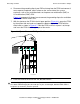
6. Disconnect the grounding clip of your ESD wriststrap from the FESA and connect it
to an exposed, unpainted, metal surface on the service side of the system
enclosure, such as the ventilation holes on the processor multifunction (PMF) or
I/O multifunction (IOMF) CRU.
Figure 4-4 on page 4-23 shows how to connect the grounding clip to the ventilation
holes on the PMF or IOMF CRU.
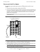
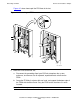
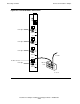
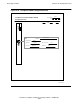
7. With the ejector on the FESA in the full-open position (Figure 4-6), grasp the FESA
by the ejector with one hand and support the bottom edge of the FESA with the
other hand as shown in Figure 4-7. Hold the FESA so that its ejector is at the top
and insert the FESA into the upper part of the carrier.
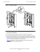
8. Push the FESA to the rear of the slot, but don't force it.
Figure 4-6. Ejector Shown in Full-Open Position
Caution. Apply equal pressure to both the top and bottom of the FESA when pushing it into
the slot to avoid damaging the connector pins. If pins are damaged, both the FESA and the
backplane (or enclosure) must be replaced.
500CDT .CDD