Fibre Channel ServerNet Adapter Installation and Support Guide Abstract This guide describes how to install, replace, and relocate a Fibre Channel ServerNet adapter (FCSA) in an HP I/O adapter module (IOAM) enclosure. This guide is written for HP service representatives who install or maintain FCSAs. Product Version N.A. Supported Release Version Updates (RVUs) This guide supports the G06.24 RVU and all subsequent G-series RVUs and the H06.
Document History Part Number Product Version Published 528254-002 N.A. September 2004 528254-003 N.A. Unpublished 528254-006 N.A. July 2005 528254-010 N.A.
Fibre Channel ServerNet Adapter Installation and Support Guide Glossary Index What’s New in This Guide vii Guide Information vii New and Changed Information Examples Figures Tables viii About This Manual ix Who Should Use This Guide ix What’s in This Guide ix Where to Get More Information ix Notation Conventions x 1.
2. Installing an FCSA Contents 2.
3. Replacing an FCSA (continued) Contents 3.
4. Relocating an FCSA (continued) Contents Verify the Installation of the FCSA 4-4 Resume Operations 4-4 Connect External Devices 4-4 4. Relocating an FCSA (continued) Alter or Add DISK Objects 4-4 Restart the Connected Devices 4-5 Troubleshooting 4-5 A. FCSA Configuration Forms for ESS Connections B. FCSA Configuration Forms for Fibre Channel Disk Connections Safety and Compliance Glossary Index Examples Example 3-1. Example 3-2.
Tables (continued) Contents Table i. Table 1-1. Table 1-2. Table 1-3. Summary of Contents -ix FCSA Cables 1-5 Power-Status and Fault-Indicator LEDs 1-7 FCSA Part Number and Product Number 1-10 Tables (continued) Table 1-4. Table 2-1. Table 2-2. Table 2-3. Table 2-4. Table 2-5. Table 2-6. Table 2-7. Table 2-8. Table 3-1. Table 3-2. Table 3-3. Table 3-4. Table 4-1. Table 4-2. Table 4-3.
Contents Fibre Channel ServerNet Adapter Installation and Support Guide —528254-010 vi
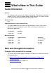
What’s New in This Guide Guide Information Fibre Channel ServerNet Adapter Installation and Support Guide Abstract This guide describes how to install, replace, and relocate a Fibre Channel ServerNet adapter (FCSA) in an HP I/O adapter module (IOAM) enclosure. This guide is written for HP service representatives who install or maintain FCSAs. Product Version N.A. Supported Release Version Updates (RVUs) This guide supports the G06.24 RVU and all subsequent G-series RVUs and the H06.
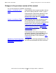
What’s New in This Guide Changes in the previous version of this manual Changes in the previous version of this manual This revision contains the additions and changes: Section 1, Introduction to the FCSA. Documentation of the range of numbers that can be used to specify group on H-Series systems. Documentation of connections between FCSAs and disk drive enclosures containing fibre channel disks in new subsection Relationship to the Disk Drive Enclosure.
About This Manual This guide describes how to install, replace, and relocate a Fibre Channel ServerNet adapter (FCSA) in an I/O Adapter Module (IOAM) enclosure. Who Should Use This Guide This guide is written for HP service representatives who install or maintain FCSAs in an IOAM enclosure. The user of this guide should have knowledge of: • • The OSM Service Connection, part of the HP NonStop Open System Management (OSM) Interface.
About This Manual Other Manuals Other Manuals Depending on the tasks you are performing, you might also need the following manuals: • • • • • OSM Migration Guide OSM User’s Guide SCF Reference Manual for the Storage Subsystem Modular I/O Installation and Configuration Guide For H-Series systems: NonStop NS-Series Hardware Installation Manual Notation Conventions Hypertext Links Blue underline is used to indicate a hypertext link within text.
About This Manual General Syntax Notation [ ] Brackets. Brackets enclose optional syntax items. For example: TERM [\system-name.]$terminal-name INT[ERRUPTS] A group of items enclosed in brackets is a list from which you can choose one item or none. The items in the list can be arranged either vertically, with aligned brackets on each side of the list, or horizontally, enclosed in a pair of brackets and separated by vertical lines. For example: FC [ num ] [ -num ] [ text ] K [ X | D ] address { } Braces.
Change Bar Notation About This Manual Item Spacing. Spaces shown between items are required unless one of the items is a punctuation symbol such as a parenthesis or a comma. For example: CALL STEPMOM ( process-id ) ; If there is no space between two items, spaces are not permitted. In this example, no spaces are permitted between the period and any other items: $process-name.#su-name Line Spacing.
1 Introduction to the FCSA This section provides an introduction to the Fibre Channel ServerNet adapter (FCSA) for I/O Adapter Module (IOAM) enclosures.
Overview of the FCSA Introduction to the FCSA Figure 1-1. FCSA Ports Port 1 2Gb 1Gb Port 1 Port 2 2Gb 1Gb Port 1 FCSA Fibre Ethernet ports: not available for FCSA Ethernet ports: not available for FCSA D C Ethernet ports: not available for FCSA VST001.vsd FCSAs are installed in slots 1 through 5 of an I/O Adapter Module (IOAM) enclosure. Since there are two logical modules in an IOAM enclosure, a total of 10 FCSAs can be installed in an enclosure. FCSAs are installed in pairs.
Overview of the FCSA Introduction to the FCSA installed one each in different IOAM enclosures. Figure 1-2 shows the slots available in the IOAM for the FCSA. Figure 1-2.
Introduction to the FCSA FCSA Features FCSA Features • Supports both 2-Gbps or 1-Gbps Fibre Channel protocol. Note. The FCSA supports both 2-Gbps and 1-Gbps fibre channel speeds. A 1-Gbps FC cable typically has a Subscriber Channel (SC connector) which does not install on an FCSA unless an adapter is used. If the ESS Fibre Channel port is a 1-Gbps port, the link operates at 1-Gbps even if the FC cable connected to the FCSA is a 2-Gbps cable.
Introduction to the FCSA FCSA External Connectors, Indicators, and Cables Figure 1-3. Connector Plugs Should be in Place When Cable is not in Use Connector Plug VST003.vsd Table 1-1.
FCSA External Connectors, Indicators, and Cables Introduction to the FCSA Figure 1-4. Power-Status and Fault-Indicator LEDs Port 1 2Gb 1Gb 2Gb 1Gb Port 1 FCSA D C Power-status LED (green) Fault-indicator LED (amber) FCSA Power and Fault LEDs new.vsd The FCSA power-status and fault-indicator LEDs are controlled by the internal hardware and indicate the adapter states described in Table 1-2.
FCSA External Connectors, Indicators, and Cables Introduction to the FCSA Table 1-2. Power-Status and Fault-Indicator LEDs LED State Description Green Not lit up Adapter is faulty or has been powered off. Lit up Adapter is powered. After installing the FCSA, the green power-status LED should come on within a minute. Amber Not lit up Adapter is functional. Lit up Adapter internal failure or service action is indicated by the software or the technician.
FCSA External Connectors, Indicators, and Cables Introduction to the FCSA Figure 1-5. Port LEDs 2-Gbps link status Port 1 (green) Port 1 2Gb 1Gb 2-Gbps link status Port 2 (green) 1-Gbps link status Port 1 (amber) 1-Gbps link status Port 2 (amber) 2Gb 1Gb Port 1 FCSA D C VST006.
FCSA External Connectors, Indicators, and Cables Introduction to the FCSA The fibre-channel port status LEDs indicate the activity on the fibre-channel ports: Hardware State Green LED (2 Gbps) Amber LED (1 Gbps) Power Off Off Off Power On, before firmware download On On Power On, after firmware initialization 1 flash 1 flash Both flashing at the same time Firmware fault 2 flashes 2 flashes Alternate flashing 1 Gbps link UP Off On 2 Gbps link UP On Off Activity at 1 Gbps Off 5 flas
FCSA Part Number and Product ID Introduction to the FCSA Figure 1-6. FCSA Label, Track ID, and Part Number Bar Code Track ID Part Number VST007.vsd FCSA Part Number and Product ID Table 1-3.
Introduction to the FCSA Data Transfer Interface (ServerNet) These connections are on the back of the FCSA and attach to the midplane. Data Transfer Interface (ServerNet) The data transfer interface consists of ports to the ServerNet X and Y fabrics. The ports connect to the ServerNet addressable controller (SAC) on the adapter. If one ServerNet fabric fails, the FCSA can still be accessed by using the remaining fabric.
RAM Firmware Introduction to the FCSA RAM Firmware For disks that are not used for system load, operational firmware is downloaded to the FCSA when you issue the first START DISK command to the first disk drive in the fibre channel loop. Manufacturing Naming Conventions HP manufacturing’s naming convention for processes and devices relates logical names to the physical location of devices. Table 1-4.
Relationship to the Enterprise Storage System (ESS) Introduction to the FCSA slot is the FCSA physical slot number in the IOAM: Number Description 1 to 5 For the FCSA. sac identifies one of the ServerNet Addressable Controllers (SACs) inside the FCSA. SACs are designated either 1 or 2. number indicates the position of the device within the system. Relationship to the Enterprise Storage System (ESS) The FCSA provides connectivity to the ESS.
Storage Subsystem SCF Attributes for ESS Connections Introduction to the FCSA Figure 1-7.
Introduction to the FCSA Storage Subsystem SCF Attributes for ESS Connections primarycpu, backupcpu define the primary and backup processor locations for the DISK process pair. primarylocation, backuplocation define the primary and backup locations (group, module, slot) of the FCSAs for the paths. primarysac, backupsac define the primary and backup ports on the FCSA for the paths. primaryportname, backupportname define the primary and backup port WWNs on the ESS for the paths.
Introduction to the FCSA • • • • Relationship to the Disk Drive Enclosure Use mirroring Use four processors Use slots in different IOAM logical modules or different IOAM enclosures Use LUNs in different ESS systems. These decisions affect the choices of the SCF attributes for the SCF ADD DISK command to the storage subsystem (see DISK Configuration (ESS Connection) on page 2-15).
Relationship to the Disk Drive Enclosure Introduction to the FCSA Figure 1-8. Disk Drive Enclosure Configuration Attributes primarycpu backupcpu CPU 0 in (1, 1, 50) CPU 2 in (2, 1, 50) ServerNet Y fabric ServerNet X fabric primarylocation backuplocation FCSA in (11, 2, 5) sac1 FCSA in (21, 3, 5) sac1 sac2 sac2 primarysac backupsac primarydeviceid (shelf, bay) A A bay1 A shelf 2 B A B A bay1 B bay14 B A shelf 1 bay14 B B VST026.
Introduction to the FCSA Storage Subsystem SCF Attributes for Disk Drive Enclosure Connections Storage Subsystem SCF Attributes for Disk Drive Enclosure Connections The SCF attributes for the paths shown in Figure 1-8 are defined as: primarycpu, backupcpu define the primary and backup processor locations for the DISK process pair. primarylocation, backuplocation define the primary and backup locations (group, module, slot) of the FCSAs for the paths.
2 Installing an FCSA This section describes how to install a Fibre Channel ServerNet adapter (FCSA) in an I/O adapter module (IOAM) enclosure.
Installing an FCSA Disk Drive Enclosure Connection To obtain the WWNs of the FCSA, you must download the firmware. To download the firmware: 1. Use SCF to add the DISK object 2. Then start the DISK object (the DISK object does not have to come up). 3. After the firmware has been downloaded, determine the FCSA WWNs by: a. Issuing the STATUS ADAPTER, DETAIL or STATUS ADAPTER, SACS command. b. Examining the Port Name and Node Name fields in the resulting display.
Tape Drive Connection Installing an FCSA The FCS Monitor is a persistent generic process. The SCF Reference Manual for the Kernel Subsystem shows how to display information about the FCS Monitor process. Tape Drive Connection Connections between host tape processes on NonStop H-Series systems and SCSI attached N1525A tape drives require the use of a M8201 Fibre Channel-to-SCSI router, which you install inside the system cabinet.
Installing an FCSA • Start Completing the Configuration Forms Define FCSAs in different modules in an IOAM enclosure or, better still, in different IOAM enclosures for the primary and backup DISK paths ESS Connections For connections to an ESS: • • Define different FC switches for the primary and backup DISK paths Define different ESSes for the primary and backup DISK images For more information about fault-tolerance planning, see the Modular I/O Installation and Configuration Guide.
Start Completing the Configuration Forms Installing an FCSA This information is on the FCSAs physical label (see Figure 1-6 on page 1-10.) 2. Record the FCSA’s Physical Location on Your FCSA Configuration Form as described in Table 2-2 Table 2-2. How to Fill in the Location of the FCSA Field Where to Obtain the Information Date Enter the date of when you are installing the FCSA System Name Use the scroll keys on the LCD on the IO switch in the IOAM to scroll to the system name.
Installing an FCSA Start Completing the Configuration Forms Table 2-3. SCF ADD DISK Command Attribute Names for ESS Connections (page 1 of 2) SCF Attribute Name/ Attribute Value Description PRIMARYCPU number The attribute values specify the primary and backup processor locations of the DISK object.
Disk Drive Enclosure Connections Installing an FCSA Table 2-3. SCF ADD DISK Command Attribute Names for ESS Connections (page 2 of 2) SCF Attribute Name/ Attribute Value Description MIRRORPORTNAME number The attribute values specify the WWNs of the mirror primary and backup Fibre Channel ports on the ESS. Obtain this information from the ESS administrator. (The choices should be guided by the overall fault-tolerant strategy for the storage subsystem configuration.
Gather the Proper Tools Installing an FCSA • Decide which of the fibre channel disks serve as primary disks and which serve as mirror disks HP provides two forms to help in these tasks: • • Configuration Form for Primary and Backup Disks Configuration Form for Mirror and Mirror Backup Disks HP also provides a SCF Disk Volume Configuration Form to help you record each primary and mirrored disk that form part of a disk volume.
Make Sure the Slot was not Previously Configured Installing an FCSA Figure 2-1.
Installing an FCSA Install the FCSA Install the FCSA Table 2-4. Installation Checklist Step Description Topic Location 1. Unpack and Inspect the FCSA Page 2-10 2. Install the FCSA Page 2-11 Unpack and Inspect the FCSA Note. Whenever you handle an FCSA, follow standard operating practices to avoid damage to the equipment. See Review Standard Operating Practices on page 2-8. 1. Put on an ESD wrist strap and attach the grounding clip to the antistatic mat. 2.
Installing an FCSA Install the FCSA Install the FCSA 1. Disconnect the grounding clip of your ESD wrist strap from the antistatic mat, then connect it to an unpainted metal surface on the FCSA. 2. Grasp the FCSA by its purple ejector latch in one hand, while supporting the bottom edge of the FCSA with the other hand. Carry the FCSA to the rear of the IOAM enclosure. Set the FCSA down on an antistatic mat with the ejector latch at the top. Note. The FCSA weighs approximately 7.25 pounds (3 kilograms). 3.
Install the FCSA Installing an FCSA Figure 2-2. Inserting the FCSA Into the Enclosure VST011.vsd 5. Press down and back on the latch; the latch slides under the top lip of the frame and secures the adapter in place. The ejector latch clicks when the adapter is fully seated. 6. Disconnect the grounding clip of your ESD wrist strap from the rack or enclosure. 7.
Label the Cables Installing an FCSA Figure 2-3. Fibre Channel Cables VST012.vsd The green power-on LED at the bottom of the adapter should now be lit. If the LED is not lit, either reseat the FCSA or install a different FCSA. Label the Cables 1. Find the group, module, and slot of the IOAM enclosure in which the FCSA is installed (see Figure 1-2 on page 1-3). 2. Tag the Fibre Channel cables connected to the FCSA with physical labels, preferably at both cable ends.
Verify the Installation of the FCSA Installing an FCSA Verify the Installation of the FCSA Table 2-5. Installation Verification Checklist Step Description Topic Location 1. Verify the Hardware Installation Page 2-14 2. Verify the Presence of the FCSA in the Configuration Database Page 2-14 3. Troubleshoot the Installation Page 2-15 Verify the Hardware Installation Verify the installation of the FCSA by examining the FCSA’s status LEDs.
Installing an FCSA Troubleshoot the Installation Troubleshoot the Installation If either of the following conditions occur: • • The SCF STATUS SAC command shows that the FCSA SAC object is still in the STARTING state after a few minutes, or The OSM Service Connection indicates that the resource needs attention: check for event messages in the Event Message Service (EMS) log. Use the OSM Event Viewer to view the EMS log.
Installing an FCSA Start the DISK ADD the DISK Using the information that you obtained in Start Completing the Configuration Forms on page 2-4, configure an SCF disk volume object for use with the ESS. The example shows an SCF ADD command that adds a mirrored DISK volume object for a hardware configuration consisting of two FCSA adapters. Because you may have to run this configuration procedure several times, it is best to create a command file.
Installing an FCSA Obtain the Fibre Channel Port WWNs and Complete the FCSA to ESS Configuration Form Obtain the Fibre Channel Port WWNs and Complete the FCSA to ESS Configuration Form Table 2-8. Obtaining the WWN Checklist Step Description Topic Location 1. Obtain the Adapter Status Page 2-18 2.
Obtain the Fibre Channel Port WWNs and Complete the FCSA to ESS Configuration Form Installing an FCSA Obtain the Adapter Status Enter the STATUS ADAPTER, DETAIL command with the detail option for the FCSA: 3-> status $ZZSTO.#FCSA.GRP-11.MOD-3.SLOT-5, d STORAGE - Detailed Adapter Type..... Flash Boot....... Flash Firmware... Location......... Part ID.......... Power-1.......... Revision Level... Tracking Number.. Status ADAPTER \MYSYS.$ZZSTO.#FCSA.GRP-11.MOD-3.SLOT-5 FCSA T0612G06 Flash Update Active....
Connect External Paths Installing an FCSA The WWN of each SAC is identified by the Port Name field. In this example, the WWN of SAC 1 is 50060B00001D535C and of SAC 2 is 50060B00001D535E. Complete the Configuration Forms Complete the FCSA to ESS Connection form. Figure 2-4 shows a sample completed form. Figure 2-4.
Installing an FCSA Connect External Paths 1. Have the FCSA connected to the FC switch or ESS (depending on whether you are using direct connect or the switched connect). Caution. Do not connect the Fibre Channel cables to the FC switch or the ESS yourself. The ESS or FC switch administrator must perform this task. 2. Update the WWN zoning in the SAN so the ESS recognizes the FCSA. Note. Adding or updating WWNs in the ESS is not required if the FCSA ports are directly connected to the ESS FC ports. 3.
DISK Configuration (Disk Drive Enclosure Connection) Installing an FCSA DISK Configuration (Disk Drive Enclosure Connection) For information about disk configuration for disk drive enclosures containing M8xxx disks, see the SCF Reference Manual for the Storage Subsystem. Verify the Disk Configuration To check that the DISK object was successfully added to the configuration database, issue the SCF STATUS ADAPTER adapter-name, DETAIL command. STORAGE - Detailed Adapter Type..... Flash Boot.......
Installing an FCSA Troubleshoot the Disk Configuration Troubleshoot the Disk Configuration If you receive errors when you try to start the DISK object, go into the OSM Event Viewer, specify Real Time, and view the service log ($ZLOG). ($ZLOG has the lowestlevel errors.) Error -2 or 190 If the file system returns an error -2 or 190 when you issue the START DISK command, you may need to initialize the disk by using the INITIALIZE DISK command.
TAPE Configuration Installing an FCSA TAPE Configuration Integrity NonStop NS-series servers can interface to SCSI-attached model N1525A tape drives by means of a M8201 Fibre Channel to SCSI router. Each M8201 router connected to an FCSA provides access to two SCSI tape drives through two ports labeled Port 1 and Port 2.
Verify the TAPE Configuration Installing an FCSA -> SAC 2, & -> SENDTO STORAGE > ADD TAPE $tape2, & -> LOCATION (110,3,2),& -> LUN 3 -> PORTNAME 100000E00Y00N000 -> SAC 2, & -> SENDTO STORAGE For more information about installing and configuring a M8201 Fibre Channel to SCSI router, see the M8201 Fibre Channel to SCSU Router Installation Guide.
Installing an FCSA Verify the TAPE Configuration For information about added tape drives, issue a INFO ADAPTER, DETAIL command: STORAGE - Detailed Info ADAPTER \IO.$ZZSTO.#FCSA.GRP-15.MOD-2.SLOT-2 Access List................... 0,1,2,3,4,5,6,7,8,9,10,11,12,13,14,15 Location (Group,Module,Slot).. (15,2,2) ServerNet Addressable Controllers: SAC \IO.$ZZSTO.#FCSA.SAC-1.GRP-15.MOD-2.
Installing an FCSA Verify the TAPE Configuration Fibre Channel ServerNet Adapter Installation and Support Guide —528254-010 2- 26
3 Replacing an FCSA This section describes how to replace a Fibre Channel ServerNet adapter (FCSA) in an IOAM enclosure. You might need to replace an FCSA if it has failed or partially failed. If POST fails and an OSM alarm is generated on the FCSA SAC, you must replace the FCSA. If you are moving the FCSA to a different slot, see Section 4, Relocating an FCSA.
Replacing an FCSA Prepare to Replace an FCSA The new adapter will have new WWNs. If the FCSA ports are directly connected to the ESS fiber channel-ports, the WWNs still may need to be updated in the ESS. Normally, the ESS subsystem recognizes the new FCSA WWNs, but if certain security parameters are set within the ESS, the ESS subsystem does not use the new WWNs automatically. If the ESS subsystem does not recognize the FCSA WWNs, when you restart the DISK object, the NonStop server returns Error 66.
Replacing an FCSA Gather the Proper Tools Gather the Proper Tools See Gather the Proper Tools on page 2-8. Print the FCSA Forms Print two copies of the FCSA Configuration Form (located in Appendix A, FCSA Configuration Forms for ESS Connections) and use one to record information about the FCSA that you are replacing and the other to record information about the new FCSA.
Replacing an FCSA Identify the Devices Example 3-1. SCF INFO DISK DETAIL Display 1-> INFO DISK $DS101, DETAIL STORAGE - Detailed Information Magnetic Common Disk Configuration Information: . . . Disk Type Specific Information: . . . Primary Path Information: Adapter............................... Disk Device ID / Port Name............ Disk Device LUN....................... Location (Group,Module,Slot).......... SAC Name.............................. SAC Number............................ $ZZSTO.#FCSA.
Replacing an FCSA Identify the Devices Example 3-2. SCF STATUS ADAPTER DETAIL Display 3-> STATUS $ZZSTO.#FCSA.GRP-11.MOD-2.SLOT-1, DETAIL STORAGE - Detailed Status ADAPTER \MYSYS.$ZZSTO.#FCSA.GRP-11.MOD-2.SLOT-1 Adapter Type..... FCSA Flash Boot........T0612G06 Flash Update Active...Done Flash Firmeare....T0630G06 Flash Update Result...Init Location......... (21,2,1) Number of SACs......... 2 Part ID.......... 526217 POST Result............ PASSED Power-1.......... ON Power-2................
Replacing an FCSA Switch the Paths to Another FCSA Switch the Paths to Another FCSA Issue the SWITCH ADAPTER, AWAY command to move all the devices’ active paths to an alternate path. (For more information about the SWITCH ADAPTER command, see the SCF Reference Manual for the Storage Subsystem.) ->SWITCH ADAPTER $ZZSTO.#FCSA.GRP-11.MOD-2.SLOT-1 , AWAY This command moves the paths to their alternates and warns you if a path cannot be switched.
Replacing an FCSA Replace the FCSA Replace the FCSA This procedure refers you to OSM to perform the Replace action but provides figures and cautions that enhance the procedures in OSM help. Table 3-2. Replacement Checklist Step Description 1. Review Standard Operating Practices 2. Use OSM to Replace the Adapter 3. Download the Firmware 4. Verify the Installation of the FCSA Note. Whenever you handle an FCSA, follow standard operating practices to avoid damage to the equipment.
Replacing an FCSA Use OSM to Replace the Adapter a. Remove the installed adapter and install the new one. For removal, consult Figure 3-1, Figure 3-2, and the text explaining them. For installation, consult Install the FCSA on page 2-11, b. If the FCSA ports are connected to the FC switch and not directly to the ESS FC ports, update the WWN zoning in the SAN so the ESS recognizes the FCSA. c. Add WWNs to the ESS host group configurations as appropriate. 7.
Replacing an FCSA Use OSM to Replace the Adapter Figure 3-1. Pressing Down on the Latch Frame Lip Press down and back on ejector VST015.vsd The procedures in OSM include the step of grasping the FCSA by its ejector latch in one hand and pulling it out of the slot while supporting the bottom edge of the FCSA with the other hand (Figure 3-2 shows this step). Note. The FCSA weighs approximately 7.
Replacing an FCSA Download the Firmware Figure 3-2. Removing the FCSA VST016.vsd Download the Firmware To download the application firmware, follow the procedure in DISK Configuration (ESS Connection) on page 2-15. Verify the Installation of the FCSA To verify the installation, follow the procedure described in Verify the Installation of the FCSA on page 2-14. Update the Firmware You can use both OSM and SCF to update the firmware.
Replacing an FCSA Download Firmware for One FCSA Table 3-3. Update the Firmware Checklist Step Description 1. Download Firmware for One FCSA 2. Download Firmware for Multiple FCSAs Download Firmware for One FCSA To download the firmware by using OSM: 1. Log on to the OSM Service Connection. 2. Expand the tree pane to locate and select the FCSA you want to check. 3. Right-click the FCSA object and select Actions. 4.
Replacing an FCSA Resume Operations some of the FCSAs are down-rev, you can easily select all down-rev FCSAs by selecting Down-rev in the Filter by drop-down list (Down-rev only appears as an option if one or more FCSAs have down-rev firmware). 6. Select the FCSAs you want to update and click Add to move them to the lower list (or click Add All to move all FCSAs listed). 7. Click Perform Action to initiate a flash boot firmware update on all FCSAs appearing in the lower list. 8.
Replacing an FCSA Verify That the Connected Devices are Operational Verify That the Connected Devices are Operational Issue the STATUS ADAPTER DETAIL command on the new adapter and ensure that all the disks that should be active are active: ->STATUS ADAPTER ZZSTO.#FCSA.GRP-11.MOD-2.SLOT-1, DETAIL Obtain the Fibre Channel Port WWNs and Complete the FCSA to ESS Configuration Form Table 3-5. Obtaining the WWN Checklist Step Description Topic Location 1. Obtain the Adapter Status Page 3-14 2.
Replacing an FCSA Obtain the Fibre Channel Port WWNs and Complete the FCSA to ESS Configuration Form Enter the STATUS ADAPTER, DETAIL command with the detail option for the FCSA: 3-> status $ZZSTO.#FCSA.GRP-11.MOD-3.SLOT-5, d STORAGE - Detailed Adapter Type..... Flash Boot....... Flash Firmware... Location......... Part ID.......... Power-1.......... Revision Level... Tracking Number.. Status ADAPTER \MYSYS.$ZZSTO.#FCSA.GRP-11.MOD-3.SLOT-5 FCSA T0612G06 Flash Update Active....
Replacing an FCSA Connect External Paths The WWN of each SAC is identified by the Port Name field. In this example, the WWN of SAC 1 is 50060B00001D535C and of SAC 2 is 50060B00001D535E. Complete the Configuration Forms Complete the FCSA to ESS Connection form. Figure 3-3 shows a sample completed form. Figure 3-3.
Replacing an FCSA Connect External Paths 1. Have the FCSA connected to the FC switch or ESS (depending on whether you are using direct connect or the switched connect). Caution. Do not connect the Fibre Channel cables to the FC switch or the ESS yourself. The ESS or FC switch administrator must perform this task. 2. Update the WWN zoning in the SAN so the ESS recognizes the FCSA. Note. Adding or updating WWNs in the ESS is not required if the FCSA ports are directly connected to the ESS FC ports. 3.
4 Relocating an FCSA This section describes how to relocate an FCSA that has been previously installed in an IOAM enclosure. Note. An FCSA can be relocated without shutting down the system. Overview of FCSA Replacement Procedures Page 4-1 Prepare to Relocate an FCSA Page 4-2 Remove and Relocate the FCSA Page 4-3 Verify the Installation of the FCSA Page 4-4 Resume Operations Page 4-4 Note.
Relocating an FCSA Prepare to Relocate an FCSA Prepare to Relocate an FCSA Table 4-1. Preparation Checklist Step Description 1. Gather the Proper Tools 2. Print the FCSA Forms 3. Determine the FCSA Physical Location 4. Identify the Devices 5. Switch the Paths 6. Stop the Paths 7. Locate the New Slot 8. Change the Labels on the Fibre Channel Cables 9. Complete the Configuration Form Gather the Proper Tools For the proper tools, refer to Gather the Proper Tools on page 2-8.
Locate the New Slot Relocating an FCSA Locate the New Slot Find the IOAM group, module, and slot containing the FCSA to be relocated and the empty slot where you will relocate it. The empty slot contains a double-high filler pane. Remove the filler panel (part number 527829)from the slot where you are relocating the FCSA. Set aside the filler panel. You will reinstall the filler panel in the slot left vacant by the FCSA you move. Change the Labels on the Fibre Channel Cables 1.
Relocating an FCSA Install the FCSA in its New Slot c. Attach the grounding clip from the ESD wrist strap to any unpainted metal surface on the IOAM enclosure or on the rack in which the enclosure is installed. Caution. Do not attach the ESD grounding clip to doors or to any painted surface. 3. Press down on the purple ejector latch and pull the FCSA’s handle outward to unseat the adapter. (See Figure 3-1, Pressing Down on the Latch, on page 3-9.) 4.
Relocating an FCSA Restart the Connected Devices If you are changing the path, you are changing the DISK path attributes, delete the DISK objects by using the SCF DELETE command, then add new DISK objects by using the SCF ADD command. See DISK Configuration (ESS Connection) on page 2-15 and Start the DISK on page 2-16. Restart the Connected Devices Use the SCF START command to restart each device connected to this adapter.
Relocating an FCSA Fibre Channel ServerNet Adapter Installation and Support Guide —528254-010 4 -6 Troubleshooting
A FCSA Configuration Forms for ESS Connections This appendix provides a forms for recording information about your FCSAs. You are authorized to photocopy this form only for the purpose of installing and configuring your HP system. When you have completed the forms, place them in your Documentation Packet. For more information about the Documentation Packet, see the NonStop S-Series Planning and Configuration Guide or the NonStop NS-Series Planning Guide.
FCSA Configuration Forms for ESS Connections FCSA Configuration Form Identifying Information About the FCSA Date:_______________ Location of the FCSA Part Number: System Name: Track ID: Group: SAC1 WWN: Module: SAC2 WWN: Slot: Information for Adding Disks to the Configuration Database Primary CPU: Backup CPU: Primary Location: Backup Location: Mirror Primary Location: Mirror Backup Location: Primary SAC: Backup SAC: Mirror Primary SAC: Mirror Backup SAC: Primary Port: Backup Port: Mir
FCSA Configuration Forms for ESS Connections Fibre-Channel ServerNet Adapter (FCSA) Configuration Form Primary LUN Information Group: Module: Primary LUN Numbers for SAC1 Slot: Primary LUN Numbers for SAC2 VST019.
FCSA Configuration Forms for ESS Connections Fibre-Channel ServerNet Adapter (FCSA) Configuration Form Mirror LUN Information Group: Module: Mirror LUN Numbers for SAC1 Slot: Mirror LUN Numbers for SAC2 VST020.
FCSA Configuration Forms for ESS Connections Fibre-Channel ServerNet Adapter (FCSA) Configuration Form Primary Port Information Group: Module: Primary Port Numbers for SAC1 Slot: Primary Port Numbers for SAC2 VST021.
FCSA Configuration Forms for ESS Connections Fibre-Channel ServerNet Adapter (FCSA) Configuration Form Backup Port Information Group: Module: Backup Port Numbers for SAC1 Slot: Backup Port Numbers for SAC2 VST022.
FCSA Configuration Forms for ESS Connections Fibre-Channel ServerNet Adapter (FCSA) Configuration Form Mirror Primary Port Information Group: Module: Mirror Primary Port Numbers for SAC1 Slot: Mirror Primary Port Numbers for SAC2 VST023.
FCSA Configuration Forms for ESS Connections Fibre-Channel ServerNet Adapter (FCSA) Configuration Form Mirror Backup Port Information Group: Module: Mirror Backup Port Numbers for SAC1 Slot: Mirror Backup Port Numbers for SAC2 VST024.
FCSA Configuration Forms for ESS Connections FCSA to ESS Connection Form FCSA Administrator Name: S A C NonStop System Name G, M, S # Date: World Wide Name of SAC World Wide Name of ESS VST018.
FCSA Configuration Forms for ESS Connections Fibre Channel ServerNet Adapter Installation and Support Guide— 528254-010 A -10
B FCSA Configuration Forms for Fibre Channel Disk Connections This appendix provides a forms for recording information about your FCSAs and the fibre channel disks that interface to them. You are authorized to photocopy this form only for the purpose of installing and configuring your HP system. When you have completed the forms, place them in your Documentation Packet. For more information about the Documentation Packet, see the the NonStop NS-Series Planning Guide.
FCSA Configuration Forms for Fibre Channel Disk Connections Configuration Form for Primary and Backup Disks Part 1 Date:_______________ FCSA Information Identifying Information About the FCSA Location of the FCSA Part Number: System Name: Track ID: Group: SAC Module: Slot: Identifying Information About the FCSA Location of the FCSA Part Number: System Name: Track ID: Group: SAC Module: Slot: VST030.
FCSA Configuration Forms for Fibre Channel Disk Connections Configuration Form for Primary and Backup Disks Part 2 Date:_______________ Disk Information Shelf number 1 2 3 4 5 6 7 8 9 10 11 12 13 14 Bay number Shelf number 1 2 3 4 5 6 7 8 9 10 11 12 13 14 Bay number Shelf number 1 2 3 4 5 6 7 8 9 10 11 12 13 14 Bay number Shelf number 1 2 3 4 5 6 7 8 9 10 11 12 13 14 Bay number VST031.
FCSA Configuration Forms for Fibre Channel Disk Connections Date:_______________ Configuration Form for Mirror and Mirror-Backup Disks Part 1 FCSA Information Identifying Information About the FCSA Location of the FCSA Part Number: System Name: Track ID: Group: SAC Module: Slot: Identifying Information About the FCSA Location of the FCSA Part Number: System Name: Track ID: Group: SAC Module: Slot: VST032.
FCSA Configuration Forms for Fibre Channel Disk Connections Configuration Form for Mirror and Mirror-Backup Disks Part 2 Date:_______________ Disk Information Shelf number 1 2 3 4 5 6 7 8 9 10 11 12 13 14 Bay number Shelf number 1 2 3 4 5 6 7 8 9 10 11 12 13 14 Bay number Shelf number 1 2 3 4 5 6 7 8 9 10 11 12 13 14 Bay number Shelf number 1 2 3 4 5 6 7 8 9 10 11 12 13 14 Bay number VST033.
FCSA Configuration Forms for Fibre Channel Disk Connections Date:_______________ SCF Disk Volume Configuration Form Disk Volume Name: Backup CPU Primary CPU System Name: Primary Disk Primary path Group: Module: Slot: SAC Shelf Bay Module: Slot: SAC Shelf Bay Module: Slot: SAC Shelf Bay Module: Slot: SAC Shelf Bay Backup path Group: Mirror Disk Mirror path Group: Mirror backup path Group: Disk Volume Name: Backup CPU Primary CPU System Name: Primary Disk Primary path Group: Mo
Safety and Compliance This sections contains three types of required safety and compliance statements: • • • Regulatory compliance Waste Electrical and Electronic Equipment (WEEE) Safety Regulatory Compliance Statements The following regulatory compliance statements apply to the products documented by this manual. FCC Compliance This equipment has been tested and found to comply with the limits for a Class A digital device, pursuant to part 15 of the FCC Rules.
Safety and Compliance Regulatory Compliance Statements Korea MIC Compliance Taiwan (BSMI) Compliance Japan (VCCI) Compliance This is a Class A product based on the standard or the Voluntary Control Council for Interference by Information Technology Equipment (VCCI). If this equipment is used in a domestic environment, radio disturbance may occur, in which case the user may be required to take corrective actions.
Safety and Compliance Regulatory Compliance Statements European Union Notice Products with the CE Marking comply with both the EMC Directive (89/336/EEC) and the Low Voltage Directive (73/23/EEC) issued by the Commission of the European Community.
Safety and Compliance SAFETY CAUTION SAFETY CAUTION The following icon or caution statements may be placed on equipment to indicate the presence of potentially hazardous conditions: DUAL POWER CORDS CAUTION: “THIS UNIT HAS MORE THAN ONE POWER SUPPLY CORD. DISCONNECT ALL POWER SUPPLY CORDS TO COMPLETELY REMOVE POWER FROM THIS UNIT." "ATTENTION: CET APPAREIL COMPORTE PLUS D'UN CORDON D'ALIMENTATION. DÉBRANCHER TOUS LES CORDONS D'ALIMENTATION AFIN DE COUPER COMPLÈTEMENT L'ALIMENTATION DE CET ÉQUIPEMENT".
Safety and Compliance Waste Electrical and Electronic Equipment (WEEE) HIGH LEAKAGE CURRENT To reduce the risk of electric shock due to high leakage currents, a reliable grounded (earthed) connection should be checked before servicing the power distribution unit (PDU).
Safety and Compliance Important Safety Information Important Safety Information Safety information for dual-threaded hardware manuals is located in two places. HP NonStop NS-Series Servers Safety information can be accessed from the left navigation area of the NTL home page: select NonStop Computing>Important Safety Information. A document window containing a binder of safety information, in several languages, appears.
Safety and Compliance Consignes de sécurité à l'intention du client Consignes de sécurité à l'intention du client Installation et entretien du système par le client Les consignes de sécurité qui suivent concernent l'installation et l'entretien par le client du système décrit dans le présent manuel. • • Garder la porte fermée pendant le fonctionnement normal du système. Installer le système à proximité des prises de courant nécessaires à son branchement. Ces prises doivent être faciles d'accès.
Safety and Compliance Declaraciones sobre la seguridad del consumidor WARNUNG. Den Gleichstrom-Steckverbinder an der vom Kunden austauschbaren PMFEinheit des S4000/S7x000 nicht berühren, nachdem das Gleichstromkabel von der vom Kunden austauschbaren Einheit abgezogen wurde. Bis zu fünfzehn (15) Sekunden nach Abziehen des Kabels besteht starke Elektroschockgefahr.
Safety and Compliance Forbrugersikkerhedsmeddelelser Forbrugersikkerhedsmeddelelser Installation og service af udstyr der udføres af kunden De følgende meddelelser vedrører sikkerheden angående installation og service af udstyr, der udføres af kunden, som beskrives i denne brugerhåndbog. • • Hold lugen lukket under normal drift. Udstyret skal installeres i nærheden af stikkontakterne til netledningerne, og stikkontakterne skal være let tilgængelige for brugeren.
Safety and Compliance Veiligheidsinstructies voor de consument Veiligheidsinstructies voor de consument Installatie en onderhoud van apparatuur door de klant De volgende veiligheidsinstructies betreffen de installatie en het onderhoud door de klant van de in deze handleiding beschreven apparatuur. • • Houd bij normaal bedrijf de deur gesloten. De apparatuur moet nabij contactdozen voor stroomkabels worden geïnstalleerd en de contactdozen moeten voor de gebruiker gemakkelijk bereikbaar zijn.
Safety and Compliance Veiligheidsinstructies voor de consument Veiligheidsinstructies voor de consument Installatie en onderhoud van apparatuur door de klant De volgende veiligheidsinstructies betreffen de installatie en het onderhoud door de klant van de in deze handleiding beschreven apparatuur. • • Houd bij normaal bedrijf de deur gesloten. De apparatuur moet nabij contactdozen voor stroomkabels worden geïnstalleerd en de contactdozen moeten voor de gebruiker gemakkelijk bereikbaar zijn.
Safety and Compliance Informações de segurança para os consumidores Informações de segurança para os consumidores Instalação e manutenção do equipamento pelo cliente As seguintes informações se referem a questões de segurança relacionadas à instalação e manutenção, pelo cliente, do equipamento descrito neste manual. • • Para garantir o funcionamento normal, mantenha a porta fechada. O equipamento deve ser instalado próximo das tomadas, e o usuário deve ter acesso fácil às tomadas. AVISO.
Safety and Compliance Meddelanden beträffande konsumentsäkerhet Meddelanden beträffande konsumentsäkerhet Kundutförd installation och service De följande meddelandena beskriver säkerhetsföreskrifter för kundutförd installation och service av utrustning som beskrivs i denna manual: • • Dörren skall vara stängd under normal drift. Utrustningen bör monters nära eluttag för nätsladdar. Nätsladdarna måste vara lättillgängliga.
Safety and Compliance Meddelanden beträffande konsumentsäkerhet S7400/ S7x000 S7400/ S7x000 Fibre Channel ServerNet Adapter Installation and Support Guide—528254-010 Statements- 14
Safety and Compliance Meddelanden beträffande konsumentsäkerhet Fibre Channel ServerNet Adapter Installation and Support Guide—528254-010 Statements- 15
Safety and Compliance Meddelanden beträffande konsumentsäkerhet Fibre Channel ServerNet Adapter Installation and Support Guide—528254-010 Statements- 16
Glossary ADAPTER object. A configurable object within the Subsystem Control Facility (SCF) interface that represents a Fibre Channel ServerNet adapter (FCSA). adapter. See also server. attribute. (1) For the Subsystem Control Facility (SCF), a characteristic of an entity. For example, two attributes of a process might be its program file and its user ID. backup processor.
Glossary event message event message. Text intended for a system operator that describes a change in some condition in the system or network, whether minor or serious. The change of condition is called an event. Events can be operational errors, notifications of limits exceeded, requests for actions needed, and so on. See also operator message. fabric. Describes a complex set of interconnections through which there can be multiple and (to the user) unknown paths from point to point.
Glossary guided procedure guided procedure. A software tool that assists you in performing complex configuration or replacement tasks on an HP NonStop S-series server. Guided procedures are accessible from the Start menu on your system console. Examples include Replace SEB or MSEB, Configure ServerNet Node, and Replace IOMF. HP NonStop Kernel. The operating system for HP NonStop S-series systems. HP NonStop process.
Glossary LUN LUN. See logical unit number (LUN). NonStop S-series servers. The set of servers in the NonStop range of servers having product numbers beginning with the letter “S.” These servers implement the ServerNet architecture and run the HP NonStop Kernel operating system. operator message. A message, intended for an operator, that describes a significant event on a NonStop S-series system. An operator message is the displayed-text form of an Event Management Service (EMS) event message.
Glossary ServerNet addressable controller (SAC) systems; and return reply messages to the clients or requesters. A server process is a running instance of a server program. ServerNet addressable controller (SAC). An I/O controller that is uniquely addressable by a ServerNet ID in a ServerNet system area network (ServerNet SAN). ServerNet SAN. See ServerNet system area network (ServerNet SAN). ServerNet system area network (ServerNet SAN).
Glossary system area network (SAN) system area network (SAN). A high-speed network, within a system, that connects processors to each other and to peripheral controllers. A SAN has the performance of a massively parallel interconnect, but has distribution capabilities similar to a local area network (LAN). NonStop S-series servers support the ServerNet system area network (ServerNet SAN). worldwide name (WWN). A unique, 64-bit number assigned to hardware ports. WWN. See worldwide name (WWN). WWN zoning.
Index Numbers 526217 1-10 A ADD DISK command 2-16 ADD DISK command example ESS disk 2-16 ALTER DISK command 4-4 Amber, LED 1-7 Antistatic table mat 2-10, 4-3 B BACKUPCPU 2-16 backupcpu 1-15, 1-18, 2-6 BACKUPLOCATION 2-16 backuplocation 1-15, 1-18, 2-6 BACKUPPORTNAME 2-16 backupportname 1-15, 2-6 BACKUPSAC 2-16 backupsac 1-15, 2-6 bay 1-18 C Cables caution 1-4, 2-12 descriptions of 1-5 labeling 2-13, 3-6 part numbers for 1-5 Cable, LC-LC, multimode 1-5 Checking for damaged pins 2-14 Command View 2-6 Confi
Index F ESD antistatic mat 2-10 illustration of ESD-protected environment 2-9 protection kit 2-8 wrist strap 2-10 ESD wrist strap 2-10, 2-11, 2-12, 4-3 ESS See Enterprise Storage System (ESS) Ethernet ports 1-1 Events Event Message Service (EMS) log 2-15 OSM Event Viewer 2-15 F Fault-indicator LED 1-5, 1-6, 1-7 Fault-tolerance 1-15 fault-tolerance 2-3 FC switch 1-4 FCSA weight 2-11 Fibre cables, caution 1-4 Fibre Channel ServerNet adapter (FCSA) checking for damaged pins 2-14 configuration form 2-4 deter
Index L I/O Adapter Module (IOAM) See IOAM L Label communication cables 3-6 Latch, ejector 1-9, 2-11, 2-12 LCD 2-5 LC-LC cable 1-5 LED fault-indicator 1-5, 1-6, 1-7 power-status 1-5, 1-6, 1-7 Location 3-3 Logical modules 1-2 Logical unit See LUN 1-13 LUN 1-13, 2-1 LUN number 2-6 M M8201 SCSI to Fibre Channel coverter 2-23 M8840 product ID 1-1 Maintenance entity (ME) connection 1-10, 1-11 Manufacturing naming conventions 1-11 MBACKUPLOCATION 2-16, 4-4 MBACKUPPORTNAME 2-16 mbackupportname 2-7 MBACKUPSAC 2
Index R Product number 1-10 R RAM firmware 1-12 Rates, disk I/O 1-4 Relocating a FCSA 4-1/4-5 Replace action 3-1 Replacing an FCSA 3-1/3-13 S SAC 1-1 sac 1-13 SAN 3-2 See Storage area network (SAN) SC connector 1-4 SCF attributes BACKUPCPU 2-16 backupcpu 1-15, 1-18, 2-6 BACKUPLOCATION 2-16 backuplocation 1-15, 1-18, 2-6 BACKUPPORTNAME 2-16 backupportname 1-15, 2-6 BACKUPSAC 2-16 backupsac 1-15, 2-6 MBACKUPLOCATION 2-16, 4-4 MBACKUPPORTNAME 2-16 mbackupportname 2-7 MBACKUPSAC 2-16 mbackupsac 2-6 MIRRORLO
Index T STATUS ADAPTER, DETAIL command 2-2 STATUS ADAPTER, SACS command 2-2 Storage area network (SAN) 1-1 Storage subsystem 1-14 SWITCH ADAPTER command 3-6 Switched connect 1-1, 2-20 System connections maintenance entity 1-10, 1-11 power interface 1-10, 1-11 ServerNet 1-10, 1-11 system 1-10 System name 2-5 Special Characters $ZLOG 2-22 $ZZSTO 2-5 T Tools needed for installation 2-8 Track ID 2-4 Troubleshooting 2-15, 2-22 adapter configuration 2-14 DISK configuration 2-22 U Unpacking a FCSA 2-10 V Ver
Index Special Characters Fibre Channel ServerNet Adapter Installation and Support Guide—528254-010 Index -6