
Fibre Channel ServerNet Adapter Installation and Support Guide (G06.24+, H06.03+)


Replacing an FCSA
Fibre Channel ServerNet Adapter Installation and Support Guide—528254-010
3-3
Gather the Proper Tools
Gather the Proper Tools
See Gather the Proper Tools on page 2-8.
Print the FCSA Forms
Print two copies of the FCSA Configuration Form (located in Appendix A, FCSA
Configuration Forms for ESS Connections) and use one to record information about
the FCSA that you are replacing and the other to record information about the new
FCSA.
If you are using the same path as the existing FCSA to connect the replacement FCSA
to the ESS, you can transfer all the information about the DISK objects to the new
form. In this case, you only need to write new information in the “Identifying Information
of the FCSA” portion of the FCSA Configuration Form. If you have a lot of disks and
paths, the appendix provides forms for recording those as well.
See Start Completing the Configuration Forms on page 2-4 for procedures for filling in
the configuration forms.
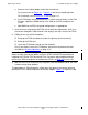
Determine the Physical Location of the FCSA
If you are replacing an FCSA because it has failed, you probably have received an
event message telling you that one of a disk’s paths is not working and this may be the
only way you know that an adapter is down. To locate the adapter that has the
problem, use the SCF INFO DISK DETAIL command to determine the FCSA’s location
(see Example 3-1). Scan the command’s output for the group, module, and slot
location of the FCSA that is running the problematic path.
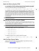
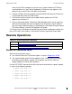
The sample command output is truncated to show just the relevant information.
->INFO DISK $DS101, DETAIL
In this example, assume that $DS101 has a problem with its primary path. Under the
Primary Path Information field, note the Location of the FCSA (group 11, module 2, slot
1).
Note. Because in this procedure you are replacing an FCSA in the same slot, you can also
retain the same information for the Location of the FCSA on the configuration form. If you are
installing the new FCSA in a new slot, use the procedure in Section 4, Relocating an FCSA
.
Note. The display in Example 3-1 shows information about an adapter interfacing to a
NonStop S-Series server. The group designation therefore has two digits. In Integrity NonStop
NS-Series servers, the group designation consists of three rather than two digits. For more
information about the group designation in NonStop S-series and Integrity NonStop NS-series
systems, see Manufacturing Naming Conventions
on page 1-12.