Gigabit Ethernet 4-Port ServerNet Adapter Installation and Support Guide Abstract This guide describes how to install, replace, and relocate a Gigabit Ethernet 4-port ServerNet adapter (G4SA) in an I/O adapter module (IOAM) enclosure. This guide is written for HP service providers who install or maintain G4SAs. Product Version N.A. Supported Release Version Updates (RVUs) This guide supports the G06.24 RVU and all subsequent G-series RVUs and the H06.06 RVU and all subsequent H-series RVUs and J06.
Document History Part Number Product Version Published 528166-002 N.A December 2004 528166-003 N.A. February 2005 528166-004 N.A. July 2005 528166-005 N.A. May 2006 528166-006 N.A.
Gigabit Ethernet 4-Port ServerNet Adapter Installation and Support Guide Glossary Index Examples Figures Tables What’s New in This Guide vii Guide Information vii New and Changed Information vii HP Encourages Your Comments viii About This Guide ix Who Should Use This Guide ix What’s in This Guide ix Where to Get More Planning Information Other Manuals x Notation Conventions x ix 1.
2. Installing a G4SA Contents 2. Installing a G4SA Prepare to Install a G4SA 2-1 Plan the Local Area Network (LAN) 2-1 Complete the Planning and Configuration Forms Gather the Proper Tools 2-3 Review Standard Operating Practices 2-3 Install a G4SA 2-5 Unpack and Inspect the G4SA 2-5 Install the G4SA 2-6 Verify the Installation of the G4SA 2-9 Add and Start the G4SA Using SCF 2-9 2-2 3.
4. Relocating a G4SA Contents 4.
Examples (continued) Contents Examples (continued) Example 3-7. Example 3-8. Example 3-9. Example 3-10. Example 3-11. Example 3-12. Example 3-13. Example 3-14. Example 3-15. Example 3-16. Example 3-17. Example 3-18. Example 3-19. Example 3-20. Example 3-21. Example 3-22. Example 3-23. Example 3-24. Example 3-25. Example 3-26. Example 3-27. Example 3-28. Example 3-29. Example 3-30. Example 3-31. Example 3-32. Example 3-33. Example 3-34. Example 3-35. Example 3-36. Example 4-1. Example 4-2. Example 4-3.
Figures Contents Figures Figure 1-1. Figure 1-2. Figure 2-1. Figure A-1. Figure A-2. Gigabit Ethernet 4-Port ServerNet Adapter (G4SA) 1-5 HP Subsystems and Utilities Using SLSA to Access a G4SA 1-8 ESD-Protected Environment 2-4 Completed G4SA Configuration Form (H-Series Systems) A-5 Completed G4SA Configuration Form (G-Series Systems) A-6 Tables Table i. Table 1-1. Table 1-2. Table 1-3. Table 1-4. Table 2-1. Table 2-2. Table 3-1. Table 3-2. Table 3-3. Table 4-1. Table 4-2. Table 4-3.
Contents Gigabit Ethernet 4-Port ServerNet Adapter Installation and Support Guide—528166-006 vi
What’s New in This Guide Guide Information Gigabit Ethernet 4-Port ServerNet Adapter Installation and Support Guide Abstract This guide describes how to install, replace, and relocate a Gigabit Ethernet 4-port ServerNet adapter (G4SA) in an I/O adapter module (IOAM) enclosure. This guide is written for HP service providers who install or maintain G4SAs. Product Version N.A. Supported Release Version Updates (RVUs) This guide supports the G06.24 RVU and all subsequent G-series RVUs and the H06.
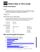
What’s New in This Guide • • • • • HP Encourages Your Comments Add and Start the G4SA Using SCF on page 2-9 Prepare to Replace a G4SA on page 3-1 Prepare to Relocate a G4SA on page 4-1 G4SA Planning and Configuration Forms on page A-1 Preparing a G4SA for Processor Replacement on page B-1 The 528166-005 version has these updates: • • Where to Get More Planning Information on page -ix Appendix A, G4SA Planning and Configuration Forms Updated G4SA slot information and manual references in: • • • • Ov
About This Guide This guide describes how to install, replace, and relocate a Gigabit Ethernet 4-port ServerNet adapter (G4SA) in an I/O adapter module (IOAM) enclosure. Who Should Use This Guide This guide is written for anyone who installs or maintains G4SAs in an IOAM enclosure in an Integrity NonStop NS-series system or Integrity NonStop BladeSystem and assumes knowledge of the: • • OSM Service Connection.
About This Guide • Other Manuals Integrity NonStop BladeSystem Planning Guide which describes the NonStop BladeSystems and associated components Other Manuals Depending on the tasks you are performing, you might also need the following manuals: • • • • • LAN Configuration and Management Manual TCP/IP (Parallel Library) Configuration and Management Manual TCP/IP Configuration and Management Manual TCP/IPv6 Configuration and Management Manual IPX/SPX Configuration and Management Manual Note.
About This Guide General Syntax Notation computer type. Computer type letters within text indicate C and Open System Services (OSS) keywords and reserved words. Type these items exactly as shown. Items not enclosed in brackets are required. For example: myfile.c italic computer type. Italic computer type letters within text indicate C and Open System Services (OSS) variable items that you supply. Items not enclosed in brackets are required. For example: pathname [ ] Brackets.
General Syntax Notation About This Guide Punctuation. Parentheses, commas, semicolons, and other symbols not previously described must be typed as shown. For example: error := NEXTFILENAME ( file-name ) ; LISTOPENS SU $process-name.#su-name Quotation marks around a symbol such as a bracket or brace indicate the symbol is a required character that you must type as shown. For example: "[" repetition-constant-list "]" Item Spacing.
Notation for Messages About This Guide !o:i. In procedure calls, the !o:i notation follows an output buffer parameter that has a corresponding input parameter specifying the maximum length of the output buffer in bytes. For example: error := FILE_GETINFO_ ( filenum , [ filename:maxlen ] ) ; !i !o:i Notation for Messages This list summarizes the notation conventions for the presentation of displayed messages in this guide. Bold Text. Bold text in an example indicates user input typed at the terminal.
Notation for Management Programming Interfaces About This Guide either vertically, with aligned braces on each side of the list, or horizontally, enclosed in a pair of braces and separated by vertical lines. For example: obj-type obj-name state changed to state, caused by { Object | Operator | Service } process-name State changed from old-objstate to objstate { Operator Request. } { Unknown. } | Vertical Line.
About This Guide Change Bar Notation Change Bar Notation Change bars are used to indicate substantive differences between this edition of the guide and the preceding edition. Change bars are vertical rules placed in the right margin of changed portions of text, figures, tables, examples, and so on. Change bars highlight new or revised information. For example: The message types specified in the REPORT clause are different in the COBOL85 environment and the Common Run-Time Environment (CRE).
About This Guide Change Bar Notation Gigabit Ethernet 4-Port ServerNet Adapter Installation and Support Guide—528166-006 xvi
1 Introduction to the Gigabit Ethernet 4-Port ServerNet Adapter (G4SA) This section provides an introduction to the Gigabit Ethernet 4-port ServerNet adapter (G4SA) for I/O adapter module (IOAM) enclosures. This section includes the following topics: Overview of the G4SA Page 1-1 G4SA System Connections Page 1-6 Relationship to the SLSA Subsystem Page 1-7 Manufacturing Naming Conventions (G06.26 and Earlier RVUs) Page 1-9 Manufacturing Naming Conventions (H06.03 and Later RVUs and J06.
Introduction to the Gigabit Ethernet 4-Port ServerNet Adapter (G4SA) G4SA Features The six supported G4SA Ethernet ports are a combination of copper and fiber interfaces, although only four of these ports can be in use at any one time. A G4SA can be configured as: • • Two 10/100/1000 Mbps copper ports and two 10/100 Mbps copper ports Two 10/100/1000 Mbps multimode fiber ports and two 10/100 Mbps copper ports A G4SA is compliant with the 1000 Base-T standard (802.3ab),1000 Base-SX standard (802.
Introduction to the Gigabit Ethernet 4-Port ServerNet Adapter (G4SA) G4SA External Connectors, Indicators, and Cables G4SA External Connectors, Indicators, and Cables The G4SA external connectors consist of: • • Four 10/100/1000 Base-T, RJ-45 type connectors Two 1000 Base-SX LC connectors with small form factor pluggables (SFPs) The G4SA external light-emitting diode (LED) indicators consist of: • • Two status LEDs for the G4SA Twelve status LEDs for the Ethernet ports The G4SA status LEDs indicate
Introduction to the Gigabit Ethernet 4-Port ServerNet Adapter (G4SA) G4SA External Connectors, Indicators, and Cables Table 1-1.
Introduction to the Gigabit Ethernet 4-Port ServerNet Adapter (G4SA) G4SA External Connectors, Indicators, and Cables Figure 1-1.
Introduction to the Gigabit Ethernet 4-Port ServerNet Adapter (G4SA) G4SA Track ID and Bar Code Label Table 1-2. G4SA Cable Specifications Port Type Connector Cable Media Maximum Distance 10 Base-T (802.3) RJ-45 male Category (CAT) 5, 5e, or 6 unshielded twisted-pair (UTP) cable 100 Meters (328 feet) 100 Base-TX (802.3u) RJ-45 male CAT 5, 5e, or 6 UTP cable 100 Meters (328 feet) 1000 Base-TX (802.
Introduction to the Gigabit Ethernet 4-Port ServerNet Adapter (G4SA) Maintenance Entity (ME) Interface Maintenance Entity (ME) Interface The Maintenance Entity (ME) interface contains the circuitry required to meet the maintenance system requirements of an active-logic adapter, which includes: • • Access to the maintenance-system features of the adapter, which allow you to: ° Power the adapter on or off ° Identify the type, configuration, and revision of the adapter A serial EEPROM (SEEROM) that provide
Introduction to the Gigabit Ethernet 4-Port ServerNet Adapter (G4SA) Accessing a G4SA through the SLSA Subsystem Accessing a G4SA through the SLSA Subsystem The SLSA subsystem provides access to the G4SA as shown in Figure 1-2. To access a G4SA through the SLSA subsystem, you can configure the following subsystems: Subsystems Description TCP/IP subsystems The TCP/IP subsystems interface the SLSA subsystem to provide TCP/IP network connectivity.
Introduction to the Gigabit Ethernet 4-Port ServerNet Adapter (G4SA) Manufacturing Naming Conventions (G06.26 and Earlier RVUs) Manufacturing Naming Conventions (G06.26 and Earlier RVUs) HP manufacturing uses a naming convention for processes and devices that relates logical names to the physical location of devices. Table 1-3. Naming Conventions for the G4SA and Related Processes (G06.24, G06.25, and G06.
Introduction to the Gigabit Ethernet 4-Port ServerNet Adapter (G4SA) Manufacturing Naming Conventions (G06.26 and Earlier RVUs) Table 1-3. Naming Conventions for the G4SA and Related Processes (G06.24, G06.25, and G06.
Introduction to the Gigabit Ethernet 4-Port ServerNet Adapter (G4SA) Manufacturing Naming Conventions (H06.03 and Later RVUs and J06.
Introduction to the Gigabit Ethernet 4-Port ServerNet Adapter (G4SA) Manufacturing Naming Conventions (H06.03 and Later RVUs and J06.03 and Later RVUs) Table 1-4. Naming Conventions for the G4SA and Related Processes (H06.03 and Later RVUs and J06.03 and Later RVUs) Process or Device Type Convention Example G4SA Adapter object Ggroup-module-slot $ZZLAN.G11123 G4SA LIF object Lgroup-module-slot-pif $ZZLAN.
Introduction to the Gigabit Ethernet 4-Port ServerNet Adapter (G4SA) Manufacturing Naming Conventions (H06.03 and Later RVUs and J06.03 and Later RVUs) pif is the G4SA’s physical interface (PIF). G4SA ports and “PIFs” are interchangeable terms. A PIF is part of the SLSA subsystem and represents the physical port on the G4SA. A G4SA has four PIFs: A, B, C, and D. m is an alphabetic value (A-Z) assigned automatically by the WAN manager process.
Introduction to the Gigabit Ethernet 4-Port ServerNet Adapter (G4SA) Manufacturing Naming Conventions (H06.03 and Later RVUs and J06.
2 Installing a G4SA This section describes how to configure and install a Gigabit Ethernet 4-port ServerNet adapter (G4SA) in an I/O adapter module (IOAM) enclosure. A G4SA can be installed without shutting down the system. This section includes the following topics: Prepare to Install a G4SA Page 2-1 Install a G4SA Page 2-5 Prepare to Install a G4SA Table 2-1. Preparation Checklist Step Description 1. Plan the Local Area Network (LAN) 2. Complete the Planning and Configuration Forms 3.
Installing a G4SA Complete the Planning and Configuration Forms Complete the Planning and Configuration Forms Complete the G4SA Planning and Configuration Forms for each G4SA you are adding to your system (see Appendix A, G4SA Planning and Configuration Forms). To add a G4SA to an IOAM enclosure, specify the: • • • • • • • • Name you want to use to identify the adapter; for example, G1123 for a G4SA in IOAM group 11, module 2, and slot 3 of the first IOAM enclosure.
Gather the Proper Tools Installing a G4SA Gather the Proper Tools You will need the following tools to install a G4SA: Tool Used to. . . Electrostatic discharge (ESD) wrist strap with grounding clip Protect the adapter against damage caused by electrostatic discharge. Flashlight Check the connectors for bent or broken pins. You can purchase an ESD kit from HP or from a local electronics store.
Review Standard Operating Practices Installing a G4SA Figure 2-1. ESD-Protected Environment ESD wriststrap with clip Antistatic floor mat 42 41 40 39 38 37 36 35 34 33 32 31 30 29 28 27 26 25 24 23 22 21 20 19 18 16 15 14 13 12 11 10 09 08 07 06 05 04 03 02 01 42 41 40 39 38 37 36 35 34 33 32 31 30 29 28 27 26 25 24 23 22 21 20 19 18 17 16 15 14 13 12 11 10 09 08 07 06 05 04 03 02 01 Antistatic table mat Grounding cord VST063.
Install a G4SA Installing a G4SA Install a G4SA Note. HP recommends that you install a G4SA first, then add the adapter using the Subsystem Control Facility (SCF). Table 2-2. Installation Checklist Step Description 1. Unpack and Inspect the G4SA 2. Install the G4SA 3. Verify the Installation of the G4SA 4. Add and Start the G4SA Using SCF Unpack and Inspect the G4SA Note. Whenever you handle a G4SA, follow standard operating practices to avoid damage to the equipment.
Install the G4SA Installing a G4SA Install the G4SA 1. Disconnect the grounding clip of your ESD wrist strap from the antistatic mat, then connect it to an unpainted metal surface on the G4SA. 2. Grasp the G4SA by its purple ejector latch in one hand and support the bottom edge of the G4SA with the other hand. Carry the G4SA to the rear of the IOAM enclosure. Set the G4SA down on an antistatic mat with the ejector latch at the top. Note. The G4SA weighs approximately 7 pounds (3 kilograms). 3.
Install the G4SA Installing a G4SA 5. Press down and back on the ejector latch; the latch will slide under the top lip of the frame and secure the adapter into place. The ejector latch clicks when the adapter is fully seated. Frame Lip Press down and back on ejector VST048.vsd 6. Disconnect the grounding clip of your ESD wrist strap from the enclosure.
Install the G4SA Installing a G4SA 7. Connect the adapter connectors to the Ethernet ports on the G4SA: a. For the copper interfaces, connect the RJ-45 connectors to the Ethernet ports on the G4SA. If you are using the fiber interfaces, connect the LC connectors to the Ethernet ports on the G4SA. b. Connect the other end of the cables to your Ethernet hub or switch. Read the labels on the cables to make sure you connect the cables to the proper ports and Ethernet hub or switch.
Installing a G4SA Verify the Installation of the G4SA Verify the Installation of the G4SA Verify the installation of the G4SA by examining the G4SA’s status LEDs. Figure 1-1 on page 1-5 shows the location of these LEDS for the G4SA. Make sure that the power-on LED (green light) is lit. Note. When the adapter is inserted, the fault LED (amber) remains lit until the adapter’s firmware completes initialization. The fault LED also lights when SLSA detects a POST failure.
Add and Start the G4SA Using SCF Installing a G4SA SCF adds a G4SA to group 11, module 2, and slot 3 of an I/O adapter module (IOAM) and gives processor 0 primary access to the ServerNet addressable controller (SAC). Processors 1 through 3 are assigned secondary access. 2. Use the SLSA subsystem SCF NAMES command to display the names assigned to the SAC and PIF of the adapter you added in Step 1. ->NAMES PIF $ZZLAN.G1123* SLSA Names PIF \SYS.$ZZLAN.G1123 PIF $ZZLAN.G1123.0.A $ZZLAN.G1123.0.B $ZZLAN.G1123.
Add and Start the G4SA Using SCF Installing a G4SA Example 2-1. SCF STATUS Commands ->STATUS ADAPTER $ZZLAN.G1123 SLSA Status ADAPTER Name State $ZZLAN.G1123 STARTED -> STATUS SAC $ZZLAN.G1123.* SLSA Status SAC Name Owner State $ZZLAN.G1123. 0 0 STARTED -> STATUS PIF $ZZLAN.G1123.* SLSA Status PIF Name $ZZLAN.G1123.0.A $ZZLAN.G1123.0.B $ZZLAN.G1123.0.C $ZZLAN.G1123.0.D State STARTED STARTED STARTED STARTED -> STATUS LIF $ZZLAN.L11* SLSA Status LIF Name $ZZLAN.L112I $ZZLAN.L112J $ZZLAN.L112K $ZZLAN.
Add and Start the G4SA Using SCF Installing a G4SA c. In the Attributes tab, compare the Firmware Version attribute with the Default File Version. If the Firmware Version is older than the Default File Version, it is down-rev and should be updated. d. Right-click the G4SA SAC object and select Actions. e. Select Firmware Update from the Available Actions list and click Perform action. • To check and update the firmware on more than one G4SA using the OSM Service Connection: a.
3 Replacing a G4SA This section describes how to perform replacement of a Gigabit Ethernet 4-port ServerNet adapter (G4SA) in an I/O adapter module (IOAM) enclosure. You might need to replace a G4SA if it has failed or partially failed. If POST fails and an OSM alarm is generated on the G4SA SAC, you must replace the G4SA. Note. A G4SA can be replaced without shutting down the system.
Print the G4SA Planning Worksheet Replacing a G4SA Print the G4SA Planning Worksheet Print the G4SA Planning Worksheet and use it to record information about a G4SA. For this worksheet, see Appendix A, G4SA Planning and Configuration Forms. Identify Any Communications Lines and ServerNet Wide Area Network (SWAN) Using the G4SA The subsystems and utilities that use the SLSA subsystem to access a G4SA are shown in Figure 1-2 on page 1-8.
Identify Any Communications Lines and ServerNet Wide Area Network (SWAN) Using the G4SA Replacing a G4SA Example 3-2. SCF INFO SUBNET Command ->INFO SUBNET $*.* TCPIP Info SUBNET \DRAGON.$ZB1EJ.* Name Devicename *IPADDRESS #LOOP0 \SYS123.$NOIOP 127.0.0.1 #SN1 \MYSYS.L112J 172.16.40.64 #SN2 \MYSYS.L01C 172.16.35.
Identify Any Communications Lines and ServerNet Wide Area Network (SWAN) Using the G4SA Replacing a G4SA Example 3-4. SCF NAMES Command ->NAMES $ZZPAM PAM Names \MYSYS.$ZZPAM PROCESS $TOK1 $ZZPAM LINE $TOK1 PORT $TOK1.#L1P0002 $TOK1.#L1P0004 MSAP $TOK1.#SNATR 4. Use the SCF INFO LINE command for the PAM lines you identified in Step 3 to determine the PAM lines associated with the LIFs on the G4SA to be replaced. Write down the associated LIFs and PAM lines on your worksheet.
Identify Any Communications Lines and ServerNet Wide Area Network (SWAN) Using the G4SA Replacing a G4SA Example 3-6. SCF NAMES SUBSYS Command ->NAMES SUBSYS $ZMGR IPXSPX Names SUBSYS \MYSYS.$ZMGR SUBSYS $ZMGR PROCESS $ZNV0 SERVER $ZNV0.#SAP PROCESS $ZNV1 SERVER $ZNV1.#SAP 6. Use the SCF INFO PROCESS command for each IPXPROTO process you identified in Step 5 to determine the IPXPROTO process associated with the LIFs on the G4SA to be replaced.
Identify Any Communications Lines and ServerNet Wide Area Network (SWAN) Using the G4SA Replacing a G4SA Example 3-8. SCF LISTDEV Command ->LISTDEV TYPE 63,0 LDev Name 109 $IPYEA 159 $IPCORE PPID 3,9 0,16 BPID 2,7 1,15 Type (63,0) (63,0) Rsize 3 3 Pri 199 199 Program \MYSYS.$DATA00.T9057ADJ.LHOBJ \MYSYS.$DATA00.T9057ADJ.LHOBJ In this example, two Expand-over-IP lines (named $IPYEA and $IPCORE) are configured on the system.
Identify Any Communications Lines and ServerNet Wide Area Network (SWAN) Using the G4SA Replacing a G4SA Example 3-10. SCF NAMES ADAPTER Command ->NAMES ADAPTER $ZZWAN.#* WanMgr Names ADAPTER $ZZWAN.#* ADAPTER $ZZWAN.#S01 $ZZWAN.#S02 10. Use the SCF INFO ADAPTER command for each SWAN concentrator you identified in Step 9 to determine if any of the SWAN concentrators configured on the system are connected to the G4SA to be replaced.
Redirect or Stop Any Customer Applications Using the G4SA Replacing a G4SA Redirect or Stop Any Customer Applications Using the G4SA 1. Notify end users that applications will be temporarily unavailable. 2. Perform any actions necessary to redirect or stop customer applications. Note. The actions required to perform this step depend on the customer’s application. Stop the Communications Lines and SWAN Concentrator Line Using the G4SA Note.
Stop the Communications Lines and SWAN Concentrator Line Using the G4SA Replacing a G4SA Example 3-14. SCF STATUS PATH Command ->STATUS PATH $PATH EXPAND Name $PATH Status PATH State STOPPED PPID 2, 15 BPID 3, 15 Lines # 2 3. Use the SCF STOP DEVICE command to stop the WAN subsystem IOPs. STOP DEVICE $ZZWAN.#device-name 4. Use the SCF STATUS DEVICE command to verify that the WAN subsystem IOPs are in the STOPPED state (see Example 3-15). STATUS DEVICE $ZZWAN.#device-name Example 3-15.
Stop the Communications Lines and SWAN Concentrator Line Using the G4SA Replacing a G4SA To Stop an Expand-over-IP Line: 1. Abort the Expand-over-IP line. • To stop a single line, use the SCF ABORT LINE command: ABORT LINE $line-name • To stop all the lines in an Expand multiline path, use the SCF ABORT PATH command: ABORT PATH $path-name 2. Verify that the Expand-over-IP line is in the STOPPED state.
To Stop a Port Access Method (PAM) Line Replacing a G4SA Example 3-19. SCF STATUS DEVICE Command ->STATUS DEVICE $ZZWAN.#LINE1 WAN Manager STATUS DEVICE for DEVICE \COWBOY.$ZZWAN.#LINE1 State :........ STOPPED LDEV number.... 110 PPIN........... 2 ,13 BPIN......... 3 ,14 To Stop an IPXPROTO Process 1. Stop the IPXPROTO process. • For a IPXPROTO process configured as a generic process, use the Kernel subsystem SCF ABORT PROCESS command: ABORT PROCESS $ZZKRN.
To Stop a Port Access Method (PAM) Line Replacing a G4SA 2. Use the SCF STATUS LINE command to verify that the PAM line is in the STOPPED state (Example 3-21). STATUS LINE $line-name Example 3-21. SCF STATUS LINE Command ->STATUS LINE $TOK1 PAM Status LINE Name $TOK1 State STOPPED Primary CPU PIN 1 278 Backup CPU -1 PIN -1 Trace OFF To Stop a TCP/IP SUBNET Caution. Make sure that the TACL session from which you are issuing SCF commands is not running on the SUBNET that you are about to stop. Note.
Replacing a G4SA Determine the Physical Location of the G4SA Determine the Physical Location of the G4SA Note. A G4SA’s ejector latch has a white label that shows the adapter’s Track ID and tracking bar code. Locate the G4SA to be replaced by using either method: • • Use the OSM Service Connection to locate and select the G4SA to be replaced. OSM shows a G4SA’s physical location in both the OSM tree pane and attributes tab. The following example shows a G4SA’s group, module, slot location (13.3.
Abort the G4SA Replacing a G4SA Example 3-23. SCF INFO ADAPTER Command -> INFO ADAPTER $ZZLAN.G1123 SLSA Info ADAPTER Name $ZZLAN.G1123 Group 11 Module 2 Slot 3 Type G4SA Abort the G4SA 1. Use the SCF ABORT LIF command for each LIF to stop access to the LIFs associated with the G4SA to be replaced. ABORT LIF $ZZLAN.lif-name 2. Use the SCF STATUS LIF command to verify that the associated LIFs are in the STOPPED state (see Example 3-24). STATUS LIF $ZZLAN.* Example 3-24.
Label the Communication Cables Connected to the G4SA Replacing a G4SA Example 3-25. SCF STATUS ADAPTER Command ->STATUS ADAPTER $ZZLAN.G1123 SLSA Status ADAPTER Name $ZZLAN.G1123 State STOPPED Label the Communication Cables Connected to the G4SA 1. Find the group, module, and slot of the IOAM in which the Gigabit Ethernet 4-port ServerNet adapter (G4SA) is installed. 2. Tag the communication cables connected to the G4SA with physical labels, preferably at both cable ends.
Remove the Adapter Replacing a G4SA 2. Disconnect the communication cables from the G4SA. 3. Put on your electrostatic discharge (ESD) wrist strap and connect the grounding clip securely to either an unpainted metal surface on the IOAM enclosure or on the rack in which the enclosure is installed (see Figure 2-1 on page 2-4). Note. The G4SA weighs approximately 7 pounds (3 kilograms). 4. Press down on the purple ejector latch and pull the G4SA’s handle outward to unseat the adapter. VST045.
Replacing a G4SA 5. Unpack and Inspect the G4SA In one hand, grasp the G4SA by its ejector latch and handle and pull the adapter out of its slot while supporting the bottom edge of the adapter with the other hand. Place the G4SA on the antistatic table mat, then put the adapter in an ESD protective bag. VST046.vsd 6. Return the G4SA to its original packing container (if available). Unpack and Inspect the G4SA Follow the procedure described in Unpack and Inspect the G4SA on page 2-5.
Replacing a G4SA Resume Operations Resume Operations Table 3-3. Resuming Operations Checklist Step Description 1. Start the G4SA 2. Restart the Communications Lines 3. Verify that the Communications Lines are Restarted 4. Resume Customer Applications Start the G4SA Start the G4SA ADAPTER object and its subordinate SAC and PIF objects by using either method: • Use the SCF START ADAPTER command with the SUB ALL option.
Start the G4SA Replacing a G4SA Using SCF to Verify that Objects Are in the STARTED State 1. Use the SCF STATUS ADAPTER command to verify the adapter is in the STARTED state (see Example 3-26). STATUS ADAPTER $ZZLAN.adapter-name.* Example 3-26. SCF STATUS ADAPTER command ->STATUS ADAPTER $ZZLAN.G1123 SLSA Status ADAPTER Name $ZZLAN.G1123 State STARTED 2. Use the SCF STATUS SAC command to verify that the ServerNet addressable controller (SAC) is in the STARTED state (see Example 3-27). STATUS SAC $ZZLAN.
Restart the Communications Lines Replacing a G4SA 4. Use the SCF START LIF command to start the logical interfaces (LIFs). START LIF $ZZLAN.lif-name 5. Use the SCF STATUS LIF to verify that the LIFs are in the STARTED state (see Example 3-29). STATUS LIF $ZZLAN.* Example 3-29. SCF STATUS LIF command ->STATUS LIF $ZZLAN.* SLSA Status LIF Name $ZZLAN.L1121I $ZZLAN.L1121J $ZZLAN.L1121K $ZZLAN.
Verify that the Communications Lines are Restarted Replacing a G4SA 4. Start an Expand-over-IP line. • To start a single line, use the SCF START LINE command. START LINE $line-name • To start all the lines in an Expand multiline path, use the SCF START PATH command. START PATH $line-name 5. Start the ServerNet wide area network (SWAN) concentrator and its associated WAN subsystem IOPs and communications lines: a.
Verify that the Communications Lines are Restarted Replacing a G4SA 2. Use the SCF STATUS PROCESS command to verify that the IPXPROTO process is started (see Example 3-31). STATUS PROCESS $line-name Example 3-31. SCF STATUS PROCESS Command ->STATUS PROCESS $ZNV2 IPXSPX Status PROCESS Process Name $ZNV2 State STARTED Diagnostic State NORMAL Trace OFF 3. Use the SCF STATUS LINE command to verify that a PAM line is started (see Example 3-32). STATUS LINE $line-name Example 3-32.
Verify that the Communications Lines are Restarted Replacing a G4SA 6. Use the SCF STATUS ADAPTER with the SUB ALL option to verify that the SWAN concentrator is in the STARTED state. STATUS ADAPTER $ZZWAN.#adapter-name, SUB ALL The SUB ALL option displays status information for the ADAPTER object and its subordinate objects. 7. Use the SCF STATUS DEVICE command to verify that the WAN subsystem IOPs are in the STARTED state (see Example 3-34). STATUS DEVICE $ZZWAN.#device-name Example 3-34.
Replacing a G4SA Resume Customer Applications Troubleshooting: If an Object is Not in the STARTED State If an object is not in the STARTED state, check for event messages in the Event Message System (EMS) log. Use the OSM Event Viewer to view the EMS log. For information about accessing and logging on to the OSM Event Viewer, see the OSM Migration Guide. Refer to the Operator Messages Manual for cause, effect, and recovery information for event messages.
4 Relocating a G4SA This section describes how to relocate a Gigabit Ethernet 4-port ServerNet adapter (G4SA) that has been previously installed in an IOAM enclosure. Note. A G4SA can be relocated without shutting down the system. This section includes the following topics: Prepare to Relocate a G4SA Page 4-1 Remove and Relocate the G4SA Page 4-4 Resume Operations Page 4-4 Note. Whenever you handle a G4SA, you should follow standard operating practices to avoid damage to the equipment.
Print the G4SA Planning Worksheet Relocating a G4SA Print the G4SA Planning Worksheet Print the G4SA Planning Worksheet and use it to record information about a G4SA. For this worksheet, see Appendix A, G4SA Planning and Configuration Forms. Identify Any Communications Lines and ServerNet Wide Area Network (SWAN) Using the G4SA Follow the procedure described in Identify Any Communications Lines and ServerNet Wide Area Network (SWAN) Using the G4SA on page 3-2.
Abort the G4SA Relocating a G4SA If you receive a message that the LIF client is still active, use the SCF ABORT LIF command to remove the LIF. 3. Use the SCF STATUS LIF command to verify that the LIFs associated with the G4SA to be relocated are in the STOPPED state (see Example 4-2): STATUS LIF $ZZLAN.* Example 4-2. SCF STATUS LIF Command ->STATUS LIF $ZZLAN.* SLSA Status LIF Name $ZZLAN.L112I $ZZLAN.L112J $ZZLAN.L112K $ZZLAN.L112L State STOPPED STOPPED STOPPED STOPPED Access State UP UP UP UP 4.
Locate the New Slot Relocating a G4SA Locate the New Slot Find the IOAM group, module, and slot containing the G4SA to be relocated and the empty slot where you will relocate the adapter. This empty slot should contain a filler panel. If it does not, you will need a filler panel for the slot left vacant by the G4SA you move.
Relocating a G4SA Complete the Planning and Configuration Forms Table 4-3. Resuming Operations Checklist Step Description 1. Complete the Planning and Configuration Forms 2. Add and Start the G4SA Using SCF Complete the Planning and Configuration Forms Follow the procedure described in Complete the Planning and Configuration Forms on page 2-2 to complete new planning and configuration forms for the relocated G4SA. Enter the group number for this enclosure in the Group Number field.
Relocating a G4SA Troubleshooting Gigabit Ethernet 4-Port ServerNet Adapter Installation and Support Guide —528166-006 4 -6
A G4SA Planning and Configuration Forms Blank Gigabit Ethernet 4-port ServerNet Adapter (G4SA) planning and configuration forms follow. You should make several copies of these forms when you are planning a new system or additions to a system. You are authorized to photocopy these forms only for the purpose of installing and configuring your HP system. When you have finished using the G4SA planning and configuration forms, place them in your Documentation Packet (if available).
G4SA Planning and Configuration Forms G4SA Planning Worksheet Page 1 of 2 Print this worksheet and use it to record information about a Gigabit Ethernet 4-port ServerNet adapter (G4SA).
G4SA Planning and Configuration Forms G4SA Planning Worksheet (Continued) Page 2 of 2 Print this worksheet and use it to record information about a Gigabit Ethernet 4-port ServerNet adapter (G4SA). Expand-Over-IP Lines: Expand Line: Expand Line: ServerNet Wide Area Network (SWAN) Concentrators: SWAN: SWAN: : WAN Subsystem Input/Output Process (IOPs): SWAN: WAN IOP: SWAN: WAN IOP: SWAN: WAN IOP: SWAN: WAN IOP: VST042.
G4SA Planning and Configuration Forms Gigabit Ethernet 4-Port ServerNet Adapter (G4SA) Configuration Form System Name Date Module Group Adapter Name: SAC Name: IP Address: SAC Access List: PIF Name: Adapter Name: SAC Name: G4SA Slot LIF Name: IP Address: SAC Access List: PIF Name: LIF Name: IP Address: Adapter Name: PIF D SAC Name: SAC Access List: PIF Name: LIF Name: PIF C PIF D PIF C Adapter Name: SAC Name: IP Address: SAC Access List: PIF Name: Adapter Name: SAC Name: PIF B PIF
G4SA Planning and Configuration Forms Figure A-1. Completed G4SA Configuration Form (H-Series Systems) \Case 1 System Name 11/04/04 Date Group Adapter Name: G11123 SAC Name: PIF Name: 111 IP Address: G11123.0 G11123.0.D IP Address: Adapter Name: G11123 G11123.0 SAC Name: G4SA PIF Name: G11123.0.C 2 Module Slot 3 192.231.036.100 SAC Access List: LIF Name: (0, 1, 2, 3) L11123D 192.231.036.200 SAC Access List: LIF Name: (0, 1, 2, 3) L11123C IP Address: 192.231.036.
G4SA Planning and Configuration Forms Figure A-2. Completed G4SA Configuration Form (G-Series Systems) \Case 1 System Name 11/04/04 Date Group Adapter Name: G1123 G1123.0 SAC Name: PIF Name: 11 IP Address: IP Address: Adapter Name: G1123 G1123.0 SAC Name: G4SA PIF Name: G1123.0.C Slot 3 192.231.036.100 SAC Access List: G1123.0.D 2 Module LIF Name: (0, 1, 2, 3) L112L 192.231.036.200 SAC Access List: LIF Name: (0, 1, 2, 3) L112K IP Address: 192.231.036.
B Preparing a G4SA for Processor Replacement Replacing a processor can result in loss of access to the G4SA associated with the system unless fault tolerance is ensured. A G4SA depends on X-fabric or Y-fabric communication from the processors in the group of enclosures with which the G4SA is associated. 1. Before replacing a processor, use the SLSA SCF STATUS SAC command with the DETAIL option to verify the associated G4SA’s fault tolerance: a.
Preparing a G4SA for Processor Replacement Gigabit Ethernet 4-Port ServerNet Adapter Installation and Support Guide—528166-006 B- 2
Safety and Compliance This section contains three types of required safety and compliance statements: • • • Regulatory compliance Waste Electrical and Electronic Equipment (WEEE) Safety Regulatory Compliance Statements The following regulatory compliance statements apply to the products documented by this manual. FCC Compliance This equipment has been tested and found to comply with the limits for a Class A digital device, pursuant to part 15 of the FCC Rules.
Safety and Compliance Regulatory Compliance Statements Korea MIC Compliance Taiwan (BSMI) Compliance Japan (VCCI) Compliance This is a Class A product based on the standard or the Voluntary Control Council for Interference by Information Technology Equipment (VCCI). If this equipment is used in a domestic environment, radio disturbance may occur, in which case the user may be required to take corrective actions.
Safety and Compliance Regulatory Compliance Statements European Union Notice Products with the CE Marking comply with both the EMC Directive (89/336/EEC) and the Low Voltage Directive (73/23/EEC) issued by the Commission of the European Community.
Safety and Compliance SAFETY CAUTION SAFETY CAUTION The following icon or caution statements may be placed on equipment to indicate the presence of potentially hazardous conditions: DUAL POWER CORDS CAUTION: “THIS UNIT HAS MORE THAN ONE POWER SUPPLY CORD. DISCONNECT ALL POWER SUPPLY CORDS TO COMPLETELY REMOVE POWER FROM THIS UNIT." "ATTENTION: CET APPAREIL COMPORTE PLUS D'UN CORDON D'ALIMENTATION. DÉBRANCHER TOUS LES CORDONS D'ALIMENTATION AFIN DE COUPER COMPLÈTEMENT L'ALIMENTATION DE CET ÉQUIPEMENT".
Safety and Compliance Waste Electrical and Electronic Equipment (WEEE) HIGH LEAKAGE CURRENT To reduce the risk of electric shock due to high leakage currents, a reliable grounded (earthed) connection should be checked before servicing the power distribution unit (PDU).
Safety and Compliance HP NonStop S-Series Servers HP NonStop S-Series Servers Customer Installation and Servicing of Equipment The following statements pertain to safety issues regarding customer installation and servicing of equipment described in this manual. • • Keep door closed for normal operation. The equipment must be installed near the receptacles for the power cords, and the receptacles must be easily accessible to the user. WARNING.
Safety and Compliance Verbraucher-Sicherheitsangaben Applicabilité des procédures, des directives et des exemples MISE EN GARDE. Les procédures et directives ainsi que les exemples y afférents contenus dans le présent manuel concernent uniquement les boîtiers et pièces des serveurs Himalaya série S décrits dans la documentation connexe. Elles ne sont applicables à aucun autre système Tandem NonStop.
Safety and Compliance Declaraciones sobre la seguridad del consumidor Declaraciones sobre la seguridad del consumidor Instalación y servicio al equipo por el consumidor Las siguientes declaraciones tienen que ver con aspectos de seguridad relacionados con la instalación y servicio al equipo por el consumidor, y que se describen en este manual. • • Mantenga la puerta cerrada durante la operación normal del equipo.
Safety and Compliance Veiligheidsinstructies voor de consument Veiligheidsinstructies voor de consument Installatie en onderhoud van apparatuur door de klant De volgende veiligheidsinstructies betreffen de installatie en het onderhoud door de klant van de in deze handleiding beschreven apparatuur. • • Houd bij normaal bedrijf de deur gesloten. De apparatuur moet nabij contactdozen voor stroomkabels worden geïnstalleerd en de contactdozen moeten voor de gebruiker gemakkelijk bereikbaar zijn.
Safety and Compliance Veiligheidsinstructies voor de consument Veiligheidsinstructies voor de consument Installatie en onderhoud van apparatuur door de klant De volgende veiligheidsinstructies betreffen de installatie en het onderhoud door de klant van de in deze handleiding beschreven apparatuur. • • Houd bij normaal bedrijf de deur gesloten. De apparatuur moet nabij contactdozen voor stroomkabels worden geïnstalleerd en de contactdozen moeten voor de gebruiker gemakkelijk bereikbaar zijn.
Safety and Compliance Informações de segurança para os consumidores Informações de segurança para os consumidores Instalação e manutenção do equipamento pelo cliente As seguintes informações se referem a questões de segurança relacionadas à instalação e manutenção, pelo cliente, do equipamento descrito neste manual. • • Para garantir o funcionamento normal, mantenha a porta fechada. O equipamento deve ser instalado próximo das tomadas, e o usuário deve ter acesso fácil às tomadas. AVISO.
Safety and Compliance Meddelanden beträffande konsumentsäkerhet Meddelanden beträffande konsumentsäkerhet Kundutförd installation och service De följande meddelandena beskriver säkerhetsföreskrifter för kundutförd installation och service av utrustning som beskrivs i denna manual: • • Dörren skall vara stängd under normal drift. Utrustningen bör monters nära eluttag för nätsladdar. Nätsladdarna måste vara lättillgängliga.
Safety and Compliance Meddelanden beträffande konsumentsäkerhet S7400/ S7x000 S7400/ S7x000 Gigabit Ethernet 4-Port ServerNet Adapter Installation and Support Guide—528166-006 Statements- 13
Safety and Compliance Meddelanden beträffande konsumentsäkerhet Gigabit Ethernet 4-Port ServerNet Adapter Installation and Support Guide—528166-006 Statements- 14
Glossary 1000Base-SX. Common name for Ethernet running over multimode cable at 1000 megabits/second (Mbps). 10Base-T. Common name for Ethernet running over twisted-pair cable at 10 megabits/second (Mbps). 100Base-T. Common name for Ethernet running over twisted-pair cable at 100 megabits/second (Mbps). 1000Base-T. Common name for Ethernet running over twisted-pair cable at 1000 megabits/second (Mbps). ADAPTER object.
Glossary customer-replaceable unit (CRU) customer-replaceable unit (CRU). A unit that can be replaced in the field either by customers or by qualified personnel trained by HP. CRUs are divided into the categories of Class 1, Class 2, and Class 3 according to the risk of causing a connectivity problem if the documented replacement procedure is not followed correctly and how much CRU-replacement training or experience is advisable. See also field-replaceable unit (FRU). download.
Glossary Fibre Channel ServerNet adapter (FCSA) Fibre Channel ServerNet adapter (FCSA). A ServerNet adapter that transmits data between an HP NonStop S-series system or NonStop NS-series system and Fibre Channel storage devices. This ServerNet adapter is installed in an IOAM enclosure. field-replaceable unit (FRU). A unit that can be replaced in the field only by qualified personnel trained by HP and cannot be replaced by customers.
Glossary Gigabit Ethernet 4-Port ServerNet adapter (G4SA) Gigabit Ethernet 4-Port ServerNet adapter (G4SA). A multiport ServerNet adapter that provides 1000 megabits/second (Mbps) data transfer rates between HP NonStop S-series systems and Ethernet LANs. The G4SA is the only LAN adapter supported for the I/O adapter module (IOAM) enclosure, and it is installed in slots 1, 2, 3, 4, and 5 of an (IOAM).
Glossary HP NonStop TCP/IP subsystem HP NonStop TCP/IP subsystem. A subsystem that allows the use of HP NonStop TCP/IP to access a NonStop S-series host from Macintosh computers, personal computers, and UNIX workstations. Applications running on a NonStop S-series system or in an Expand network can transparently exchange data with NonStop TCP/IP devices. IOMF CRU. See I/O multifunction (IOMF) CRU. IOMF 2 CRU. See I/O multifunction (IOMF) 2 CRU. I/O multifunction (IOMF) CRU.
Glossary LIF system. Each LAN monitor process has ownership of the Ethernet adapters controlled by the SLSA subsystem. The LAN manager process assigns adapter ownership. See ServerNet LAN Systems Access (SLSA) subsystem and LAN Manager (LANMAN) process. LIF. See logical interface (LIF). LED. See light-emitting diode (LED). light-emitting diode (LED). A semiconductor device that emits light from its surface. Indicator lights are composed of LEDs. local area network (LAN).
Glossary Parallel Library TCP/IP series servers. Provides the same functionality as TSM while overcoming limitations of TSM. OSM is required for support of new functionality released with the G06.21 RVU and later. Parallel Library TCP/IP. An HP product that provides increased performance and scalability over conventional Transmission Control Protocol/Internet Protocol (TCP/IP).
Glossary protocol the processor and memory board (PMB), the multifunction I/O board (MFIOB), and the power supply subassembly. protocol. A set of rules used by processes or devices for exchanging data. SAC. See ServerNet addressable controller (SAC). SCF. See Subsystem Control Facility (SCF). ServerNet adapter. A customer-replaceable unit (CRU) that connects peripheral devices to the rest of the system though a ServerNet bus interface (SBI).
Glossary Simple Network Management Protocol (SNMP) Simple Network Management Protocol (SNMP). An asynchronous request-response protocol used for network management. SNMP originated as a means for managing Transmission Control Protocol over Internet Protocol (TCP/IP) and Ethernet networks. slot. A physical, labeled space for a customer-replaceable unit (CRU) or field-replaceable unit (FRU) that is part of a module. A module contains one or more slots. slot location.
Glossary Wide Area Network (WAN) Wide Area Network (WAN). A network that operates over a larger geographical area than that was provided by a local area network (LAN). The elements of a WAN may be separated by distances great enough to require telephone communications. See also local area network (LAN). $ZZLAN. The name of the ServerNet LAN Systems Access (SLSA) subsystem manager process that is started by the $ZZKRN Kernel subsystem manager process and maintained by the $ZPM persistence manager process.
Index A Adapter See Gigabit Ethernet 4-port ServerNet adapter (G4SA) Assigning LIFs 2-10 B Bar code 1-6 C Checking for damaged pins 2-9 Configuration form Gigabit Ethernet 4-port ServerNet adapter (G4SA) 2-2 D Damaged pins 2-5 Determining IP addresses 3-2 LIF names 3-2 physical location of the G4SA 3-13 E ESD antistatic mat 2-5 illustration of ESD-protected environment 2-4 protection kit 2-3 wrist strap 2-5 Events Event Message Service (EMS) log 2-11 OSM Event Viewer 2-11, 3-24 Expand aborting Expand-o
Index I Gigabit Ethernet 4-port ServerNet adapter (G4SA) (continued) preparing for PMF or IOMF CRU replacement B-1 printing the G4SA worksheet 3-1 relationship to SLSA subsystem 1-7 relocating 4-1/4-5 replacing 3-1/3-24 RJ-45 connectors 2-8 starting 3-18 stopping 3-14, 4-2 tools needed for installing 2-3 Track ID 1-6 unpacking 2-5 verifying installation 2-9 I Identifying Expand-over-IP line 3-5 IPXPROTO process 3-4 PAM line 3-4 Installing a G4SA 2-1/2-12 tools needed for 2-3 Introduction Gigabit Ethernet
Index P P PAM line identifying 3-4 stopping 3-11 Physical location of the G4SA, determining 3-13 Planning and configuration forms, Gigabit Ethernet 4-port ServerNet adapter (G4SA) A-1/A-6 PMF Ethernet adapter CRU, naming convention for 1-9 POST failure 2-9 Processorid 1-10 Processor replacement preparing a G4SA for B-1 R Redirect or stop customer applications 3-8 Relocating a G4SA 4-1/4-5 Replacing a G4SA 3-1/3-24 RJ-45 connectors 2-8 S SAC objects, verifying 3-19 SCF adding a G4SA using 2-9 creating an
Index U TFTP server processes, naming convention for 1-10, 1-12 Tools needed for installation 2-3 Track ID 1-6 U Unpacking a G4SA 2-5 V Verifying installation of a G4SA 2-9 SAC objects 3-19 W WAN manager process, naming convention for 1-9, 1-12 WANBoot processes, naming convention for 1-10, 1-12 Special Characters $ZZLAN 1-7 Gigabit Ethernet 4-Port ServerNet Adapter Installation and Support Guide—528166-006 Index-4