Gigabit Ethernet Adapter Installation and Support Guide Abstract This guide describes how to install, replace, and relocate a Gigabit Ethernet ServerNet adapter (GESA) on an HP NonStop™ S-series server. This guide is written for anyone who installs or maintains a GESA. Product Version N.A. Supported Release Version Updates (RVUs) This guide supports G06.22 and all subsequent G-series RVUs until otherwise indicated by its replacement publication. Part Number Published 523628.
Document History Part Number Product Version Published 523628.001 N.A. May 2002 523628.002 N.A. February 2003 523628.003 N.A. May 2003 523628.004 N.A. September 2003 523628.005 N.A.
Gigabit Ethernet Adapter Installation and Support Guide Glossary Index Examples Figures Tables What’s New in This Guide vii Guide Information vii New and Changed Information vii HP Encourages Your Comments viii About This Guide ix Who Should Use This Guide ix What’s in This Guide ix Where to Get More Information ix Notation Conventions x 1.
3. Replacing a GESA Contents Install a GESA 2-8 Unpack and Inspect the GESA 2-8 Install the GESA 2-9 Verify the Installation of the GESA 2-15 Add and Start the GESA Using SCF 2-16 3.
4. Relocating a GESA (continued) Contents 4.
Examples (continued) Contents Examples (continued) Example 3-14. Example 3-15. Example 3-16. Example 3-17. Example 3-18. Example 3-19. Example 3-20. Example 3-21. Example 3-22. Example 3-23. Example 3-24. Example 3-25. Example 3-26. Example 3-27. Example 3-28. Example 3-29. Example 3-30. Example 3-31. Example 3-32. Example 3-33. Example 3-34. Example 3-35. Example 3-36. Example 4-1. Example 4-2. Example 4-3.
Tables Contents Tables Table i. Table 1-1. Table 2-1. Table 2-2. Table 3-1. Table 3-2. Table 3-3. Table 4-1. Table 4-2. Table 4-3. Summary of Contents ix Naming Convention for LAN Subsystem and Related Processes Preparation Checklist 2-2 Installation Checklist 2-8 Preparation Checklist 3-2 Replacement Checklist 3-16 Resuming Operations Checklist 3-19 Preparation Checklist 4-2 Replacement Checklist 4-5 Resuming Operations Checklist 4-5 Gigabit Ethernet Adapter Installation and Support Guide— 523628.
Contents Gigabit Ethernet Adapter Installation and Support Guide— 523628.
What’s New in This Guide Guide Information Gigabit Ethernet Adapter Installation and Support Guide Abstract This guide describes how to install, replace, and relocate a Gigabit Ethernet ServerNet adapter (GESA) on an HP NonStop™ S-series server. This guide is written for anyone who installs or maintains a GESA. Product Version N.A. Supported Release Version Updates (RVUs) This guide supports G06.22 and all subsequent G-series RVUs until otherwise indicated by its replacement publication.
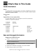
What’s New in This Guide HP Encourages Your Comments Changes to the 523628-004 Version • • • • • • As of G06.22, the HP Open System Management (OSM) product replaces TSM as the system management tool of choice for HP NonStop S-Series systems. OSM offers a browser-based interface that improves scalability and performance and overcomes other limitations that exist in TSM. TSM is still supported, but OSM is required to support new functionality in G06.22 and later.
About This Guide This guide describes how to install, replace, and relocate a Gigabit Ethernet ServerNet adapter (GESA) on a NonStop S-series server. This guide is written for anyone who installs or maintains a GESA. Who Should Use This Guide This guide is written for anyone who installs or maintains GESAs on NonStop S-series servers and assumes knowledge of the: • • OSM Service Connection or TSM Service Application.
Other Manuals About This Guide Other Manuals Depending on the tasks you are performing, you might also need the following manuals: • • • • • • LAN Configuration and Management Manual TCP/IP (Parallel Library) Configuration and Management Manual TCP/IP Configuration and Management Manual TCP/IPv6 Configuration and Management Manual IPX/SPX Configuration and Management Manual PAM Configuration and Management Manual Notation Conventions Hypertext Links Blue underline is used to indicate a hypertext link w
General Syntax Notation About This Guide italic computer type. Italic computer type letters within text indicate C and Open System Services (OSS) variable items that you supply. Items not enclosed in brackets are required. For example: pathname [ ] Brackets. Brackets enclose optional syntax items. For example: TERM [\system-name.]$terminal-name INT[ERRUPTS] A group of items enclosed in brackets is a list from which you can choose one item or none.
Notation for Messages About This Guide Quotation marks around a symbol such as a bracket or brace indicate the symbol is a required character that you must type as shown. For example: "[" repetition-constant-list "]" Item Spacing. Spaces shown between items are required unless one of the items is a punctuation symbol such as a parenthesis or a comma. For example: CALL STEPMOM ( process-id ) ; If there is no space between two items, spaces are not permitted.
Notation for Messages About This Guide Bold Text. Bold text in an example indicates user input typed at the terminal. For example: ENTER RUN CODE ?123 CODE RECEIVED: 123.00 The user must press the Return key after typing the input. Nonitalic text. Nonitalic letters, numbers, and punctuation indicate text that is displayed or returned exactly as shown. For example: Backup Up. lowercase italic letters. Lowercase italic letters indicate variable items whose values are displayed or returned.
Notation for Management Programming Interfaces About This Guide % Percent Sign. A percent sign precedes a number that is not in decimal notation. The % notation precedes an octal number. The %B notation precedes a binary number. The %H notation precedes a hexadecimal number.
1 Introduction to the Gigabit Ethernet ServerNet Adapter (GESA) This section provides an introduction to the Gigabit Ethernet ServerNet adapter (GESA) for NonStop S-series systems. This section includes the following topics: Overview of the GESA Page 1-2 GESA System Connections Page 1-7 Relationship to the SLSA Subsystem Page 1-8 Manufacturing Naming Conventions Page 1-11 Gigabit Ethernet Adapter Installation and Support Guide —523628.
Introduction to the Gigabit Ethernet ServerNet Adapter (GESA) Overview of the GESA Overview of the GESA Note. GESAs (including GESA connections via S-series I/O enclosures) are not supported on NonStop BladeSystems. The Gigabit Ethernet ServerNet adapter (GESA) is a single-port ServerNet adapter that provides Gigabit connectivity between NonStop S-series systems and Ethernet LANs. A GESA can be directly installed in slots 51 through 54 of an I/O enclosure and slots 53 and 54 of a processor enclosure.
Introduction to the Gigabit Ethernet ServerNet Adapter (GESA) • • GESA-C External Connectors, Indicators, and Cables Supported by OSM and TSM client software to facilitate diagnostics and maintenance. Supports bandwidth-intensive applications. GESA-C External Connectors, Indicators, and Cables The GESA-C external connector consist of one 10/100/1000 Base-T RJ-45 type connector.
Introduction to the Gigabit Ethernet ServerNet Adapter (GESA) GESA-C External Connectors, Indicators, and Cables Figure 1-1. Gigabit Ethernet ServerNet Adapter Copper Version (GESA-C) Gigabit Ethernet ServerNet Adapter Copper (GESA-C) Power-on LED (green) Fault LED (amber) Ejector RJ-45 Connector 1000 Base-T Mbps (green) 100 Base-T Mbps (green) 10 Base-T Mbps (green) Activity Indicator (green) VST018.vsd Gigabit Ethernet Adapter Installation and Support Guide —523628.
Introduction to the Gigabit Ethernet ServerNet Adapter (GESA) GESA-F External Connectors, Indicators, and Cables The GESA-C cable specifications and cable distances are: Port Type Connector Cable Media Maximum Distance 10 Base-T (802.3) RJ-45 Category (CAT) 3, 4, or 5 unshielded twisted-pair (UTP) cable 100 Meters (328 feet) 100 Base-TX (802.3u) RJ-45 CAT 5 UTP (2-pair) 100 Meters (328 feet) 1000 Base-T (802.
Introduction to the Gigabit Ethernet ServerNet Adapter (GESA) GESA-F External Connectors, Indicators, and Cables Figure 1-2. Gigabit Ethernet ServerNet Adapter Fiber Version (GESA-F) Gigabit Ethernet ServerNet Adapter Fiber (GESA-F) Power-On LED (green) Fault LED (amber) Ejector SC Connector 1000 Base-T Mbps (green) Activity Indicator (green) VST019.vsd Gigabit Ethernet Adapter Installation and Support Guide —523628.
Introduction to the Gigabit Ethernet ServerNet Adapter (GESA) GESA System Connections The GESA-F cable specifications and cable distances are: Port Type Connector Cable Media Maximum Distance 1000 Base-SX (802.z) SC duplex 850 nanometers (nm) multimode fiber 500 meters (1640 feet) at full duplex 1000 Base-SX (802.z) SC duplex 62.5/125 micrometers (υm) multimode fiber 220 meters (722 feet) 1000 Base-SX (802.
Introduction to the Gigabit Ethernet ServerNet Adapter (GESA) Diagnostic Subsystem Interface (Serial Maintenance Bus) Diagnostic Subsystem Interface (Serial Maintenance Bus) The diagnostics subsystem interface is supported by the serial maintenance bus (SMB).
Introduction to the Gigabit Ethernet ServerNet Adapter (GESA) Accessing a GESA through the SLSA Subsystem the logical interface (LIF) associated with the PIF. The LANMON process reports any state transitions to other LANMON processes. Note. SCF commands issued to the LANMONs or the LANMAN will not be accepted while processes are starting or if the backup LANMAN is taking over from the primary LANMAN. The SLSA subsystem will return the following error message: SLSA process is busy....
Introduction to the Gigabit Ethernet ServerNet Adapter (GESA) Accessing a GESA through the SLSA Subsystem Figure 1-3. How HP Subsystems and Utilities Use the SLSA Subsystem to Access a GESA Processor User Applications File System Interface Socket Lib WAN IOP QIO Shared Memory Segment Expand WAN TCP/IP IPX/SPX PAM SLSA Processes LIF LAN Drivers and Interrupt Handlers Y Fabric X Fabric GESA Legend SLSA Subsystem VST005.vsd Gigabit Ethernet Adapter Installation and Support Guide —523628.
Introduction to the Gigabit Ethernet ServerNet Adapter (GESA) Manufacturing Naming Conventions Manufacturing Naming Conventions HP manufacturing’s naming convention for processes and devices relates logical names to the physical location of devices. Table 1-1. Naming Convention for LAN Subsystem and Related Processes Process or Device Type Convention Example LAN Manager (LANMAN) process Must be $ZZLAN $ZZLAN Logical interface (LIF) $ZZLAN.Lcabid-portid $ZZLAN.
Introduction to the Gigabit Ethernet ServerNet Adapter (GESA) Manufacturing Naming Conventions Slot Number Port Number portid Slot Number Port Number portid 51 3 3 53 3 B 52 0 4 54 0 C 52 1 5 54 1 D 52 2 6 54 2 E 52 3 7 54 3 F For more information about suggested naming conventions, refer to the LAN Configuration and Management Manual. Gigabit Ethernet Adapter Installation and Support Guide —523628.
2 Installing a GESA This section describes how to configure and install a Gigabit Ethernet ServerNet adapter (GESA) in a NonStop S-series system enclosure. A GESA can be installed without shutting down the system. This section includes the following topics: Prepare to Install a GESA Page 2-2 Install a GESA Page 2-8 Gigabit Ethernet Adapter Installation and Support Guide —523628.
Prepare to Install a GESA Installing a GESA Prepare to Install a GESA Table 2-1. Preparation Checklist Step Description 1. Plan the Local Area Network (LAN). 2. Complete the Configuration Form. 3. Gather the Proper Tools. 4. Review Standard Operating Practices.
Complete the Configuration Form Installing a GESA Complete the Configuration Form Complete a GESA Configuration Form for each GESA you are adding to your system (see Appendix A, GESA Configuration Form). To add a GESA to a NonStop S-series system enclosure, specify the: • • • • • Name you want to use to identify the adapter; for example, E0153 for a GESA in slot 53 of the first system enclosure. Location of the adapter within the system cabinet (group, module, and slot).
Complete the Configuration Form Installing a GESA Figure 2-1. GESA Slot Locations NonStop S-Series I/O Enclosures (Service Side) 50 55 51 52 53 NonStop S-Series Processor Enclosures (Service Side) 50 55 51 54 56 I/O enclosures can use slots 51 through 54 for GESAs. 52 53 54 56 Processor enclosures can only use slots 53 and 54 for GESAs. VST057.vsd Gigabit Ethernet Adapter Installation and Support Guide —523628.
Complete the Configuration Form Installing a GESA Figure 2-2. GESA Installed in an I/O Enclosure Filler Panel Filler Panel GESA Fast Ethernet ServerNet Adapter (FESA) VST020.vsd Gigabit Ethernet Adapter Installation and Support Guide —523628.
Gather the Proper Tools Installing a GESA Gather the Proper Tools You will need the following tools to install a GESA: Tool Used to. . . Electrostatic discharge (ESD) wrist strap with grounding clip Protect the adapter against damage caused by electrostatic discharge. Flashlight Check the connectors for bent or broken pins. You can purchase an ESD kit from HP or from a local electronics store. Note.
Review Standard Operating Practices Installing a GESA Figure 2-3. ESD-Protected Environment System Enclosure (Appearance Side) ESD wriststrap with clip ESD wriststrap clipped to door latch stud (or to any exposed, unpainted, metal surface on the enclosure frame.) ESD floor mats ESD antistatic table mat. Mat should be connected to a soft ground . (1 megohm min. to 10 megohm max.) Clip 15 inch straight ground cord to screw on grounded outlet cover. VST693.
Install a GESA Installing a GESA Install a GESA Note. HP recommends that you install a GESA first, then add the adapter using the Subsystem Control Facility (SCF). Table 2-2. Installation Checklist Step Description 1. Unpack and Inspect the GESA. 2. Install the GESA. 3. Verify the Installation of the GESA. 4. Add and Start the GESA Using SCF. Unpack and Inspect the GESA Note. Whenever you handle a GESA, follow standard operating practices to avoid damage to the equipment.
Install the GESA Installing a GESA Install the GESA 1. Disconnect the grounding clip of your ESD wrist strap from the antistatic mat, then connect it to an unpainted metal surface on the GESA. 2. Grasp the GESA by its ejector in one hand, while supporting the bottom edge of the GESA with the other hand. Carry the GESA to the service side of the system enclosure. Set the GESA down on an antistatic mat right side up with the ejector at the top. Note. The GESA weights 6.75 pounds (3 kilograms). 3.
Install the GESA Installing a GESA 4. Unlatch the ejector on the adapter and pull the ejector upward into its full-open position: Ejector in Full-Open Position VST510.vsd Gigabit Ethernet Adapter Installation and Support Guide —523628.
Install the GESA Installing a GESA 5. Using both hands, hold the GESA so that its ejector is at the top. Carefully insert the adapter into its slot in the enclosure. Push the GESA to the rear of its slot, but don't force it. Caution. To avoid damaging the connector pins, apply equal pressure to both the top and bottom of the GESA when pushing it into its slot. If the pins are damaged, both the GESA and the backplane (or enclosure) must be replaced. VST075.
Install the GESA Installing a GESA 6. Press the GESA ejector latch down to seat the GESA against the backplane. VST076.vsd 7. Disconnect the grounding clip of your ESD wrist strap from the enclosure. Gigabit Ethernet Adapter Installation and Support Guide —523628.
Install the GESA Installing a GESA 8. Connect the adapter connector to the Ethernet port on the GESA: • For a 3865 GESA-C: a. Connect the RJ-45 connector to the Ethernet port on the GESA. b. Connect the other end of the cable to your Ethernet hub. Use the label on the cable to make sure you connect the cable to the proper port and Ethernet hub. 3865 Gigabit Ethernet ServerNet Adapter Copper (GESA-C) RJ-45 Connector 1000 100 10 ACT Ethernet Hub VST060.
Install the GESA Installing a GESA • For a 3865 GESA-F: a. Connect the SC connector to the Ethernet port on the GESA. b. Connect the other end of the cable to your Ethernet hub. Use the label on the cable to make sure you connect the cable to the proper port and fiber-optic Ethernet hub. 3865 Gigabit Ethernet ServerNet Adapter Fiber (GESA-F) Fiber-Optic Cable SC Connector 1000 ACT Fiber-Optic Hub VST061.vsd Gigabit Ethernet Adapter Installation and Support Guide —523628.
Verify the Installation of the GESA Installing a GESA Verify the Installation of the GESA Verify the installation of the GESA by examining the GESA’s status LEDs. Figure 1-1 on page 1-4 shows the location of these LEDS for the 3865 GESA-C. Figure 1-2 on page 1-6 shows the location of these LEDs for the 3865 GESA-F. • Make sure that the power-on LED (green light) is lit. Note.
Add and Start the GESA Using SCF Installing a GESA Add and Start the GESA Using SCF With your completed GESA configuration form as a guide, use the SCF interface to the SLSA subsystem to add and start the GESA. Note. Refer to the LAN Configuration and Management Manual for detailed information about the SLSA subsystem SCF commands. Adding and Starting the GESA 1. Use the SLSA subsystem SCF ADD ADAPTER command to add the GESA. ->ASSUME PROCESS $ZZLAN ->ADD ADAPTER $ZZLAN.
Add and Start the GESA Using SCF Installing a GESA Example 2-1. SCF STATUS Commands ->STATUS ADAPTER $ZZLAN.E0153 SLSA Status ADAPTER Name State $ZZLAN.E0153 STARTED -> STATUS SAC $ZZLAN.E0153.* SLSA Status SAC Name Owner State $ZZLAN.E0153. 0 0 STARTED -> STATUS PIF $ZZLAN.E0153.* SLSA Status PIF Name $ZZLAN.E0153.0.A State STARTED -> STATUS LIF $ZZLAN.L01* SLSA Status LIF Name $ZZLAN.
Add and Start the GESA Using SCF Installing a GESA ° To check and update the firmware on more than one GESA using the OSM Service Connection: a. Log on to the OSM Service Connection. b. From the Display menu, select Multi-Resource Actions (this brings up the Multi-Resource Actions dialog box). c. Select GESA SAC from the Resource Type drop-down list. d. Select Firmware Update from the Action drop-down list. e.
Add and Start the GESA Using SCF Installing a GESA For information about configuring the NonStop TCP/IP, Parallel Library TCP/IP, NonStop TCP/IPv6, IPX/SPX, or Port Access Method (PAM) subsystems to access the GESA through the SLSA subsystem, refer to the following manuals: • • • • • • LAN Configuration and Management Manual TCP/IP Configuration and Management Manual TCP/IP (Parallel Library) Configuration and Management Manual TCP/IPv6 Configuration and Management Manual PAM Configuration and Managemen
Installing a GESA Add and Start the GESA Using SCF Gigabit Ethernet Adapter Installation and Support Guide —523628.
3 Replacing a GESA This section describes how to perform online replacement of a Gigabit Ethernet ServerNet adapter (GESA) in a NonStop S-series server. You might need to replace a GESA if it has failed or partially failed. If POST fails and an OSM or TSM alarm is generated on the GESA SAC, you must replace the GESA. Note. A GESA can be replaced without shutting down the system. Caution.
Prepare to Replace a GESA Replacing a GESA Prepare to Replace a GESA GESAs can be installed in slots 53 and 54 of a processor enclosure and in slots 51, 52, 53, and 54 of an I/O enclosure (see Figure 2-1 on page 2-4). GESA slots should not be left empty. When no GESA is installed in a slot, a ServerNet adapter filler panel (U09021) should be installed in the empty slot to maintain proper air flow and to reduce electromagnetic interference (EMI). Note.
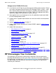
Print the GESA Planning Worksheet Replacing a GESA Print the GESA Planning Worksheet Print Figure 3-1, the GESA Planning Worksheet, and use it to record information about a GESA. Figure 3-1. GESA Planning Worksheet GESA Planning Worksheet Print this worksheet and use it to record information about a Gigabit Ethernet ServerNet adapter (GESA).
Replacing a GESA Identify Any Communications Lines and ServerNet Wide Area Network (SWAN) Using the GESA Identify Any Communications Lines and ServerNet Wide Area Network (SWAN) Using the GESA The subsystems and utilities that use the SLSA subsystem to access a GESA are shown in Figure 1-3 on page 1-10. The following procedure helps you identify the subsystems and utilities that are configured to use a GESA.
Replacing a GESA Identify Any Communications Lines and ServerNet Wide Area Network (SWAN) Using the GESA 2. Use the SCF INFO SUBNET command to determine the TCP/IP process, subnet, and Internet Protocol (IP) address associated with the LIF on the GESA to be replaced (see Example 3-2). Write down the associated LIF, TCP/IP process, subnet, and IP address on your worksheet. INFO SUBNET $*.* Example 3-2. SCF INFO SUBNET Command ->INFO SUBNET $*.* TCPIP Info SUBNET \DRAGON.$ZB018.
Replacing a GESA Identify Any Communications Lines and ServerNet Wide Area Network (SWAN) Using the GESA Example 3-4. SCF NAMES Command ->NAMES $ZZPAM PAM Names \SAMCAT.$ZZPAM PROCESS $TOK1 $ZZPAM LINE $TOK1 PORT $TOK1.#L1P0002 $TOK1.#L1P0004 MSAP $TOK1.#SNATR 4. Use the SCF INFO LINE command for the PAM line you identified in Step 3 to determine the PAM Line associated with the LIF on the GESA to be replaced (see Example 3-5). Write down the associated LIF and PAM line on your worksheet.
Replacing a GESA Identify Any Communications Lines and ServerNet Wide Area Network (SWAN) Using the GESA 6. Use the SCF INFO PROCESS command for the IPXPROTO process you identified in Step 5 to determine the IPXPROTO process associated with the LIF on the GESA to be replaced. Write down the associated LIF and IPXPROTO process on your worksheet. INFO PROCESS $process-name Example 3-7.
Replacing a GESA Identify Any Communications Lines and ServerNet Wide Area Network (SWAN) Using the GESA Example 3-9). Write down the Expand-over-IP line that uses the TCP/IP process and IP address on your worksheet. INFO LINE $line-name, DETAIL Example 3-9. SCF INFO LINE Command ->INFO LINE $IPYEA,DETAIL EXPAND Detailed Info LINE *Associatedev... $ZTC23 Framesize...... 132 *Timerinactivity 0:00:00.00 *AfterMaxRetries PASSIVE *Timerreconnect. 0:00:30.00 *DestIpAddr 172.17.203.37 *SrcIpAddr 172.17.208.
Replacing a GESA Redirect or Stop Any Customer Applications Using the GESA 11. If a SWAN concentrator is connected to the GESA CRU to be replaced, determine the names of the WAN subsystem IOPs configured to use that SWAN concentrator by using the SCF INFO DEVICE command (see Example 3-12). Write down the WAN subsystem IOPs that use the concentrator on your worksheet. INFO DEVICE $ZZWAN.#* Example 3-12. SCF INFO DEVICE command ->INFO DEVICE $ZZWAN.#* WAN MANAGER Detailed Info Device \TAHITI.$ZZWAN.
Replacing a GESA Stop the Communications Lines and SWAN Concentrator Line Using the GESA Example 3-13. SCF STATUS LINE Command ->STATUS LINE $LINE1 EXPAND Status LINE Name $LINE1 State STOPPED • PPID 2, 10 BPID 3, 7 CIU-Path A ConMgr-LDEV 91 To verify an Expand multiline path is stopped, use the SCF STATUS PATH command (see Example 3-14): STATUS PATH $path-name Example 3-14.
Replacing a GESA Stop the Communications Lines and SWAN Concentrator Line Using the GESA Example 3-16. SCF STATUS ADAPTER Command ->STATUS ADAPTER $ZZWAN.#S01 WAN Manager STATUS ADAPTER for ADAPTER \COWB0Y.$ZZWAN.#S01 State....... STOPPED Number of clips. 3 Clip 1 status : CONFIGURED Clip 2 status : CONFIGURED Clip 3 status : CONFIGURED To Stop an Expand-over-IP Line: 1. Abort the Expand-over-IP line.
Replacing a GESA Stop the Communications Lines and SWAN Concentrator Line Using the GESA 3. Use the SCF STOP DEVICE command to stop the WAN subsystem IOPs. STOP DEVICE $ZZWAN.#device-name 4. Use the SCF STATUS DEVICE command to verify that the WAN subsystem IOPs are in the STOPPED state (see Example 3-19). STATUS DEVICE $ZZWAN.#device-name Example 3-19. SCF STATUS DEVICE Command ->STATUS DEVICE $ZZWAN.#LINE1 WAN Manager STATUS DEVICE for DEVICE \COWBOY.$ZZWAN.#LINE1 State :........ STOPPED LDEV number....
Replacing a GESA Stop the Communications Lines and SWAN Concentrator Line Using the GESA To Stop a Port Access Method (PAM) Line 1. Use the SCF STOP command with the SUB ALL option to stop the PAM line. STOP LINE $line-name, SUB ALL The SUB ALL option aborts the LINE object and all subordinate objects. 2. Use the SCF STATUS LINE command to verify that the PAM line is in the STOPPED state (Example 3-21). STATUS LINE $line-name Example 3-21.
Replacing a GESA Determine the Physical Location of the GESA Determine the Physical Location of the GESA 1. Use the SCF INFO ADAPTER command to determine the GESA’s location (see Example 3-23). Scan the command’s output for the group, module, and slot location of the GESA: INFO ADAPTER $ZZLAN.adapter-name Example 3-23. SCF INFO ADAPTER Command -> INFO ADAPTER $ZZLAN.E0153 SLSA Info ADAPTER Name $ZZLAN.E0153 Group 1 Module 1 Slot Type 53 GESA Note.
Replacing a GESA • Label the Communication Cable Connected to the GESA Or, use the OSM Service Connection or TSM Service Application: 1. Log on. 2. Expand the tree pane to locate and select the GESA. 3. Right-click the GESA and select Actions. 4. Select Abort from the list of actions. 5. Click Perform action. 4. Use the SCF STATUS ADAPTER command to verify that the GESA ADAPTER object is in the STOPPED state (see Example 3-25). STATUS ADAPTER $adapter-name Example 3-25.
Replacing a GESA Replace the GESA Replace the GESA Table 3-2. Replacement Checklist Step Description 1. Review Standard Operating Practices. 2. Remove the Adapter. 3. Unpack and Inspect the GESA. 4. Install the GESA 5. Verify the Installation of the GESA. Note. Whenever you handle a GESA, follow standard operating practices to avoid damage to the equipment. Review Standard Operating Practices See Review Standard Operating Practices on page 2-6. Remove the Adapter 1.
Replacing a GESA Remove the Adapter 3. Unlatch the ejector on the GESA by pressing the blue-green tab on the ejector and pulling the ejector outward to unseat the GESA from its backplane. VST055.vsd Gigabit Ethernet Adapter Installation and Support Guide—523628.
Replacing a GESA Unpack and Inspect the GESA 4. Grasp the GESA by its ejector in one hand and slowly pull the GESA out of the slot while supporting the bottom edge of the GESA with the other hand. Note. The GESA weighs 6.75 pounds (3 kilograms). VST062.vsd Unpack and Inspect the GESA Follow the procedure described in Unpack and Inspect the GESA on page 2-8. Install the GESA Follow the procedure described in Install the GESA on page 2-9. Gigabit Ethernet Adapter Installation and Support Guide—523628.
Replacing a GESA Verify the Installation of the GESA Verify the Installation of the GESA Follow the procedure described in Verify the Installation of the GESA on page 2-15. Resume Operations Table 3-3. Resuming Operations Checklist Step Description 1. Start the GESA. 2. Restart the Communications Lines. 3. Verify that the Communications Lines are Restarted. 4. Resume Customer Applications.
Replacing a GESA Start the GESA Using SCF to Verify that Objects Are in the STARTED State 1. Use the SCF STATUS ADAPTER command to verify the adapter is in the STARTED state (see Example 3-26). STATUS ADAPTER $ZZLAN.adapter-name.* Example 3-26. SCF STATUS ADAPTER command ->STATUS ADAPTER $ZZLAN.E0153 SLSA Status ADAPTER Name $ZZLAN.E0153.0 State STARTED 2. Use the SCF STATUS SAC command to verify that the ServerNet addressable controller (SAC) is in the STARTED state (see Example 3-27).
Replacing a GESA Restart the Communications Lines 4. Use the SCF START LIF command to start the logical interface (LIF). START LIF $ZZLAN.lif-name 5. Use the SCF STATUS LIF to verify that the LIF is in the STARTED state (see Example 3-29). STATUS LIF $ZZLAN.* Example 3-29. SCF STATUS LIF command ->STATUS LIF $ZZLAN.* SLSA Status LIF Name $ZZLAN.
Replacing a GESA Verify that the Communications Lines are Restarted 4. Start an Expand-over-IP line. • To start a single line, use the SCF START LINE command. START LINE $line-name • To start all the lines in an Expand multiline path, use the SCF START PATH command. START PATH $line-name 5. Start the ServerNet wide area network (SWAN) concentrator and its associated WAN subsystem IOPs and communications lines: a.
Replacing a GESA Verify that the Communications Lines are Restarted 2. Use the SCF STATUS PROCESS command to verify that the IPXPROTO process is started (see Example 3-31). STATUS PROCESS $line-name Example 3-31. SCF STATUS PROCESS Command ->STATUS PROCESS $ZNV2 IPXSPX Status PROCESS Process Name $ZNV2 State STARTED Diagnostic State NORMAL Trace OFF 3. Use the SCF STATUS LINE command to verify that a Port Access Method (PAM) line is started (see Example 3-32). STATUS LINE $line-name Example 3-32.
Replacing a GESA Verify that the Communications Lines are Restarted 6. Use the SCF STATUS ADAPTER with the SUB ALL option to verify that the SWAN concentrator is in the STARTED state. STATUS ADAPTER $ZZWAN.#adapter-name, SUB ALL The SUB ALL option displays status information for the ADAPTER object and its subordinate objects. 7. Use the SCF STATUS DEVICE command to verify that the WAN subsystem IOPs are in the STARTED state (see Example 3-34). STATUS DEVICE $ZZWAN.#device-name Example 3-34.
Replacing a GESA Resume Customer Applications Troubleshooting: If an Object is Not in the STARTED State If an object is not in the STARTED state, check for event messages in the Event Message System (EMS) log. Use the OSM Event Viewer or TSM EMS Event Viewer Application to view the EMS log. For information about logging on or viewing the EMS log, see the the online help within the event viewer. Refer to the Operator Messages Manual for cause, effect, and recovery information for event messages.
Replacing a GESA Resume Customer Applications Gigabit Ethernet Adapter Installation and Support Guide—523628.
4 Relocating a GESA This section describes how to relocate a Gigabit Ethernet ServerNet adapter (GESA) that has been previously installed in a NonStop S-series system enclosure. A GESA can be relocated without shutting down the system. Caution. If a previously installed GESA and backplane connector have damaged pins, remove the GESA and install a filler panel (U09021) in the empty slot (see Figure 2-2 on page 2-5). Attach red tags to the filler panel to identify the slot.
Relocating a GESA Prepare to Relocate a GESA Prepare to Relocate a GESA GESAs can be installed in slots 53 and 54 of a processor enclosure and in slots 51, 52, 53, and 54 of an I/O enclosure (see Figure 2-1 on page 2-4). GESA slots should not be left empty. When no GESA is installed in a slot, a ServerNet adapter filler panel (U09021) should be installed in the empty slot to maintain proper air flow and to reduce electromagnetic interference (EMI). Note.
Relocating a GESA Stop the Communications Lines and SWAN Concentrator Line Using the GESA Stop the Communications Lines and SWAN Concentrator Line Using the GESA Follow the procedure described in Stop the Communications Lines and SWAN Concentrator Line Using the GESA on page 3-9. Determine the Physical Location of the GESA Follow the procedure described in Determine the Physical Location of the GESA on page 3-14: Stop the GESA 1.
Relocating a GESA Locate the New Slot 4. Stop the GESA object and its subordinate objects using either of the following ways: • Use the SCF STOP ADAPTER command with the SUB ALL option: STOP ADAPTER $adapter-name, SUB ALL The SUB ALL option stops the ADAPTER object and all its subordinate objects • Or, use the OSM Service Connection or TSM Service Application: 1. Log on. 2. Expand the tree pane to locate and select the GESA. 3. Right-click the GESA and select Actions. 4.
Relocating a GESA Remove and Relocate the GESA Remove and Relocate the GESA Table 4-2. Replacement Checklist Step Description 1. Review Standard Operating Practices. 2. Remove the Adapter. 3. Move the GESA and Install It in Its New Slot. 4. Verify the Installation of the GESA. Note. Whenever you handle a GESA, follow standard operating practices to avoid damage to the equipment. Review Standard Operating Practices See Review Standard Operating Practices on page 2-6 and Figure 2-3 on page 2-7.
Relocating a GESA Complete the Configuration Form Complete the Configuration Form Follow the procedure described in Complete the Configuration Form on page 2-3 to complete a new configuration form for the relocated GESA. Enter the group number for this enclosure in the Group Number field. Add and Start the GESA Using SCF Using your completed GESA configuration form as a guide, follow the procedure described in Adding and Starting the GESA on page 2-16.
A GESA Configuration Form A blank Gigabit Ethernet ServerNet Adapter (GESA) configuration form follows. You should make several copies of this form when you are planning a new system or additions to a system. You are authorized to photocopy this form only for the purpose of installing and configuring your HP system. When you have finished using the GESA Configuration Form, place it in your Documentation Packet.
GESA Configuration Form Gigabit Ethernet ServerNet Adapter (GESA) Configuration Form System Name Date Group FNET: Module 01 Slot IP Address: Adapter Name: SAC Name: SAC Access List: PIF Name: LIF Name: VST010.vsd Gigabit Ethernet Adapter Installation and Support Guide—523628.
GESA Configuration Form Figure A-1. Completed GESA Configuration Form Date Group FNET: IP Address: Adapter Name: E 0153 SAC Name: E 0153.0 PIF Name: E 0153.0.A \Case1 System Name Gigabit Ethernet ServerNet Adapter (GESA) Configuration Form 01 Module 01 01 / Slot 21 / 02 53 192.231.036.100 (0,1) SAC Access List: LIF Name: L018 VST003.vsd Gigabit Ethernet Adapter Installation and Support Guide—523628.
GESA Configuration Form Gigabit Ethernet Adapter Installation and Support Guide—523628.
B Preparing a GESA for PMF or IOMF CRU Replacement A GESA depends on X-fabric or Y-fabric communication from the PMF or IOMF CRUs in the group of enclosures where the GESA is installed. For NonStop S-series servers, replacing a PMF or IOMF CRU can result in loss of access to the GESA unless fault tolerance is ensured. 1. Before replacing a PMF or IOMF CRU, use the SLSA SCF STATUS SAC command with the DETAIL option to verify the associated GESA’s fault tolerance: a.
Preparing a GESA for PMF or IOMF CRU Replacement 2. Depending on your application, use either of the following methods to replace a PMF or IOMF CRU: • If you are using TSM, start from the toolbar located on the desktop of your system console and select either: START > Programs > Compaq TSM > Guided Replacement Tools>Replace PMF START > Programs > Compaq TSM > Guided Replacement Tools>Replace IOMF For information about these guided procedures, refer to the online help for these procedures.
Safety and Compliance Regulatory Compliance Statements The following regulatory compliance statements apply to the products documented by this guide. FCC Compliance This equipment has been tested and found to comply with the limits for a Class A digital device, pursuant to part 15 of the FCC Rules. These limits are designed to provide reasonable protection against harmful interference when the equipment is operated in a commercial environment.
Safety and Compliance Regulatory Compliance Statements Taiwan (BSMI) Compliance JAPAN (VCCI) Com p lian ce Gigabit Ethernet Adapter Installation and Support Guide—523628.
Safety and Compliance Regulatory Compliance Statements DECLARATION OF CONFORMITY Supplier Name: HP COMPUTER CORPORATION Supplier Address: HP Computer Corporation NonStop Enterprise Division 10300 North Tantau Ave Cupertino, CA 95014 USA Represented in the EU By: Hewlett Packard Company P.O.
Safety and Compliance Consumer Safety Statements Consumer Safety Statements Customer Installation and Servicing of Equipment The following statements pertain to safety issues regarding customer installation and servicing of equipment described in this manual. • • Keep door closed for normal operation. The equipment must be installed near the receptacles for the power cords, and the receptacles must be easily accessible to the user. WARNING.
Safety and Compliance Consignes de sécurité à l'intention du client Consignes de sécurité à l'intention du client Installation et entretien du système par le client Les consignes de sécurité qui suivent concernent l'installation et l'entretien par le client du système décrit dans le présent manuel. • • Garder la porte fermée pendant le fonctionnement normal du système. Installer le système à proximité des prises de courant nécessaires à son branchement. Ces prises doivent être faciles d'accès.
Safety and Compliance Verbraucher-Sicherheitsangaben Verbraucher-Sicherheitsangaben Geräteinstallation und -wartung durch den Kunden Die folgenden Angaben betreffen Sicherheitsfragen in Hinsicht auf die Geräteinstallation und -wartung durch den Kunden, wie sie in diesem Handbuch beschrieben werden. • • Tür für normalen Betrieb geschlossen lassen. Die Geräte müssen in der Nähe der Steckdosen für die Netzanschlußkabel installiert werden, und die Steckdosen müssen für den Benutzer leicht zugänglich sein.
Safety and Compliance Declaraciones sobre la seguridad del consumidor Declaraciones sobre la seguridad del consumidor Instalación y servicio al equipo por el consumidor Las siguientes declaraciones tienen que ver con aspectos de seguridad relacionados con la instalación y servicio al equipo por el consumidor, y que se describen en este manual. • • Mantenga la puerta cerrada durante la operación normal del equipo.
Safety and Compliance Forbrugersikkerhedsmeddelelser Forbrugersikkerhedsmeddelelser Installation og service af udstyr der udføres af kunden De følgende meddelelser vedrører sikkerheden angående installation og service af udstyr, der udføres af kunden, som beskrives i denne brugerhåndbog. • • Hold lugen lukket under normal drift. Udstyret skal installeres i nærheden af stikkontakterne til netledningerne, og stikkontakterne skal være let tilgængelige for brugeren.
Safety and Compliance Käyttöturvaa koskevia huomautuksia Käyttöturvaa koskevia huomautuksia Asiakkaan suorittama laiteasennus ja huolto Seuraavat huomautukset koskevat turvallisuusnäkökohtia, jotka asiakkaan täytyy ottaa huomioon tässä käsikirjassa kuvattuja laiteasennuksia ja huoltotoimenpiteitä suoritettaessa. • • Kansi täytyy pitää suljettuna normaalin käytön aikana. Laitteisto täytyy asentaa lähelle virtapistokkeita, ja pistokkeiden tulee olla helposti käytettävissä. VAARA.
Safety and Compliance Misure precauzionali per i clienti Misure precauzionali per i clienti Installazione e manutenzione del sistema da parte del cliente Le seguenti misure precauzionali riguardano l’installazione e la manutenzione da parte del cliente del sistema descritto nel presente manuale. • • Mantenere la porta chiusa durante il funzionamento normale del sistema. Il sistema deve essere installato vicino alle prese di corrente che saranno usate per il collegamento alla rete.
Safety and Compliance Informações de segurança para os consumidores Informações de segurança para os consumidores Instalação e manutenção do equipamento pelo cliente As seguintes informações referem-se a questões de segurança relacionadas à instalação e manutenção, pelo cliente, do equipamento descrito neste manual. • • Para garantir o funcionamento normal, mantenha a porta fechada. O equipamento deve ser instalado próximo das tomadas, e o utilizador deve ter acesso fácil às tomadas. AVISO.
Safety and Compliance Meddelanden beträffande konsumentsäkerhet S7400/ S7600/ S7x000 S7400/ S7600/ S7x000 Gigabit Ethernet Adapter Installation and Support Guide—523628.
Safety and Compliance Meddelanden beträffande konsumentsäkerhet S7400/ S7600/ S7x000 Gigabit Ethernet Adapter Installation and Support Guide—523628.
Safety and Compliance Meddelanden beträffande konsumentsäkerhet Gigabit Ethernet Adapter Installation and Support Guide—523628.
Glossary 10Base-T. Common name for Ethernet running over twisted-pair cable at 10 megabits/second (Mbps). 100Base-T. Common name for Ethernet running over twisted-pair cable at 100 megabits/second (Mbps). 1000Base-T. Common name for Ethernet running over twisted-pair cable at 1000 megabits/second (Mbps). ADAPTER object. A configurable object within the wide area network (WAN) subsystem Subsystem Control Facility (SCF) interface that represents a SWAN 2 concentrator. adapter. See also server. attribute.
Glossary controller controller. See ServerNet addressable controller (SAC). CRU. See customer-replaceable unit (CRU). customer-replaceable unit (CRU). A unit that can be replaced in the field either by customers or by qualified personnel trained by HP. CRUs are divided into the categories of Class 1, Class 2, and Class 3 according to the risk of causing a connectivity problem if the documented replacement procedure is not followed correctly and how much CRU-replacement training or experience is advisable.
Glossary FESA FESA. See Fast Ethernet ServerNet adapter (FESA). field-replaceable unit (FRU). A unit that can be replaced in the field only by qualified personnel trained by HP and cannot be replaced by customers. A unit is classified as a FRU because of safety hazards such as weight, size, sharp edges, or electrical potential; contractural agreements with suppliers; or national or international standards. See also customer-replaceable unit (CRU). file name. A unique name for a file.
Glossary HP NonStop TCP/IP HP NonStop TCP/IP. An HP implementation of Transmission Control Protocol/Internet Protocol (TCP/IP) for the HP NonStop range of servers. See also Parallel Library TCP/IP. HP NonStop TCP/IPv6. An HP implementation of Transmission Control Protocol/Internet Protocol (TCP/IP) for the HP NonStop range of servers. HP NonStop TCP/IP6 has the full functionality of the Parallel Library TCP/IP product and, in addition, provides access to networks that use IPv6 addressing.
Glossary LANMAN LANMAN. See LAN Manager (LANMAN) process. LAN Manager (LANMAN) process. The LANMAN process is provided as part of the SLSA subsystem. The NonStop Kernel persistence manager starts and manages the LANMAN process, which it starts as a generic process that runs as a NonStop process pair in the host system processors.
Glossary multifunction I/O board (MFIOB) multifunction I/O board (MFIOB). A ServerNet adapter that contains ServerNet addressable controllers (SACs) for SCSI and Ethernet; a service processor; ServerNet links to the processor, to the two ServerNet adapter slots, and to one of the ServerNet expansion board (SEB) slots; and connections to the serial maintenance bus (SMB), which connects components within an enclosure to the service processor. network.
Glossary processor processor. (1) The central processing unit (CPU). The processor reads program instructions, moves data between processor memory and the ServerNet addressable controllers (SACs), and performs arithmetic operations. (2) One or more computer chips, typically mounted on a logic board, that are designed to perform data processing or to manage a particular aspect of computer operations. processor multifunction (PMF) CRU.
Glossary ServerNet LAN Systems Access (SLSA) subsystem ServerNet LAN Systems Access (SLSA) subsystem. The software that allows the protocol I/O processes (IOPs) and drivers to access the ServerNet adapters. ServerNet SAN. See ServerNet system area network (ServerNet SAN). ServerNet system area network (ServerNet SAN). A wormhole-routed, full-duplex, packet-switched, point-to-point network designed with special attention to reducing latency and ensuring reliability.
Glossary subsystem subsystem. (1) a secondary or subordinate system, usually capable of operating independently of or asynchronously with a controlling system. (2) A program or set of processes that manages a cohesive set of Subsystem Control Facility (SCF) objects. Each subsystem has a manager through which applications can request services by issuing commands defined by that subsystem. See also subsystem manager. Subsystem Control Facility (SCF).
Glossary $ZZLAN Gigabit Ethernet Adapter Installation and Support Guide—523628.
Index A Adapter See Gigabit Ethernet ServerNet adapter (GESA) Assigning LIFs 2-16 C Checking for damaged pins 2-15 Configuration form Gigabit Ethernet ServerNet adapter (GESA) 2-3, A-1/A-3 D Damaged pins 2-8, 3-1, 4-1 Determining IP addresses 3-5 LIF names 3-4 physical location of the GESA 3-14 E ESD antistatic mat 2-8 illustration of ESD-protected environment 2-7 protection kit 2-6 wrist strap 2-8 Events Event Message Service (EMS) log 2-17 OSM Event Viewer 2-17 TSM EMS Event Viewer Application 2-17 Exp
Index I Gigabit Ethernet ServerNet adapter (GESA) (continued) RJ-45 connectors 2-13 SC connectors 2-14 service class 3-2 slot locations 2-3, 2-4 starting 3-19 stopping 3-14, 4-3 tools needed for installing 2-6 unpacking 2-8 verifying installation 2-15 LANMAN backup 1-8 primary 1-8 LANMON adapter ownership 1-8 LIFs assigning 2-16 determining names of 3-4 starting 3-21 I Manufacturing naming conventions 1-11, 3-14 Identifying Expand-over-IP line 3-7 IPXPROTO process 3-6 PAM line 3-6 Installation Compaq
Index S Replacing a GESA 3-1/3-25 RJ-45 connectors 2-13 S SAC objects verifying 3-20 SC connectors 2-14 SCF adding a GESA using 2-16 creating an SCF log 3-4 SCF commands ABORT LIF 3-14, 4-3 ABORT LINE 3-9, 3-11 ADD ADAPTER 2-16 ADD LIF 2-16 INFO ADAPTER 3-14 INFO DEVICE 3-9 INFO LINE 3-6 INFO PROCESS 3-7 INFO SUBNET 3-5 LISTDEV 3-7 NAMES 2-16, 3-5 NAMES ADAPTER 3-8 START ADAPTER 2-16 START LIF 3-21 STATUS ADAPTER 3-20 STATUS DEVICE 3-24 STATUS LIF 3-14, 4-3 STATUS PATH 3-10, 3-24 STATUS PIF 3-20 STATUS S
Index Special Characters Gigabit Ethernet Adapter Installation and Support Guide— 523628.