
Measure Reference Manual


Syslink Counters
Syslink counters measure the time required to complete a message link to a remote system. Whenever
a value is added to a syslink counter, a corresponding link counter is advanced. The syslink counter
is a special case of a response time counter where the transaction is a message link.
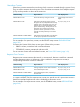
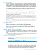
Units Displayed As...Output Value Is...Attribute Setting
ms, sec, hr, day, or wkAverage link time for each transaction.REPORT RATE is ON.
ms, sec, hr, day, or wkLink time.REPORT RATE is OFF.
Link time, expressed in microseconds.REPORT FORMAT is STRUCTURED.
For examples of syslink counters, see the SYSTEM entity counters LINKS (page 356) and LINK-TIME
(page 356).
Timer Cell Counters
The dynamics of loose processor synchronization in HP Integrity NonStop NS-series systems (which
run H-series and J-series RVUs) make the standard time-of-day functions less accurate than on
systems running G-series RVUs when viewed at microsecond granularity.
For very fine resolution measurements, events that can complete within the context of a dispatch
or a simple message exchange between two processes in the same processor, measured time
values might be distorted. This distortion is not an issue for longer running timers that encompass
the completion of interprocessor messages or I/O. The degree of error in such measurements is
marginal relative to the length of the event.
To provide more accurate timing services for Measure and other applications, the H-series and
J-series architecture provides a mechanism called timer cells. This mechanism makes it possible to
keep accurate fine granularity timers without incurring the cost of loose processor synchronization
on all timer updates. Timer cell values are synchronized only when copied at intervals or reported
to the requesting application.
The timer cell counter types are TCELLBUSY, TCELLQUEUE, and TCELLQBUSY. They operate under
the same instrumentation logic as the BUSY, QUEUE, and QBUSY counter types, respectively.
Measure uses the new counter types for several predefined entities. You can also specify the new
types for user-defined (USERDEF) entities.
Identifying Data File Errors
The first field of the output record for each measured entity type indicates whether a problem
prevented measurement or record allocation.
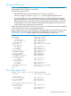
Table 3 ZMS Style Format Error Field Values
MeaningValue
No errors or warnings regarding data in the record.ERROR = 0
Error occurred, data is not present. The object to measure is identified but a counter record
was not started because of:
ERROR > 0
1 = ERR^NOCIDENTRY — Data record error: CID table overflow
2 = ERR^NOCOUNTERSPACE — Data record error: Counter space overflow
3 = ALREADY^INUSE — Data record error: Sampling conflict
4 = ERR^XPTR^INSTALL — Data record error: Measure internal error
Warning, data is present but with noted exceptions. For the specific cause, see the remaining
values:
ERROR < 0
Numeric overflow. In totals record accumulation, one or more counter fields overflowed..<1>
Counters Overview 143