N1524A ACL Installation and User’s Guide for the NonStop S-Series Tape Enclosure Abstract This guide is written for installers, users, and maintainers of the N1524A ACL in a NonStop S-Series tape enclosure. Product Version N.A. Supported Release Version Updates (RVUs) This publication supports G06.21 and all subsequent G-series RVUs until otherwise indicated in a new edition.
Document History Part Number Product Version 527340-001 N.A.
N1524A ACL Installation and User’s Guide for the NonStop S-Series Tape Enclosure Index Figures Tables What’s New in This Manual vii Manual Information vii New and Changed Information About This Manual ix Notation Conventions Abbreviations xiii vii ix 1. Overview and Features Manual Overview 1-1 Product Overview 1-1 N1524A ACL Tape Drive 1-1 NonStop S-Series Tape Enclosure High Capacity Tape Cartridge 1-14 1-7 2.
2. Installing and Configuring the Tape Drive (continued) Contents 2. Installing and Configuring the Tape Drive (continued) Set Autoclean Mode 2-10 Set Negotiation 2-10 Set Reserved Slots 2-10 Set Default (Restricted) 2-11 3. Configuring the Tape Drive for the NonStop S-Series Server Supported Connections 3-1 Adding a Tape Drive 3-1 ServerNet/DA 3-1 PMF CRU 3-2 4.
. Maintaining the Tape Drive Contents 5. Maintaining the Tape Drive Cleaning the Tape Drive 5-1 Installing the Cleaning Cartridge 5-1 Installing 5-1 Running From the Front Panel 5-2 Removing the Cleaning Cartridge 5-5 6. Servicing the Tape Drive Removing a Tape Drive from the Tape Enclosure Adding a Tape Drive to the Tape Enclosure 6-1 6-1 A.
C. Error Recovery Procedures and Fault Symptom Codes (continued) Contents C. Error Recovery Procedures and Fault Symptom Codes (continued) Inter-module Error Codes Boot Error Codes C-15 Flash Error Codes C-16 C-12 Safety and Compliance Index Figures Figure 1-1. Figure 1-2. Figure 1-3. Figure 1-4. Figure 1-5. Figure 1-6. Figure 1-7. Figure 1-8. Figure 2-1. Figure 2-2. Figure 2-3. Figure 2-4. Figure 2-5. Figure 2-6. Figure 2-7. Figure 4-1. Figure 4-2. Figure 4-3. Figure 4-4. Figure 4-5. Figure 4-6.
Figures (continued) Contents Figures (continued) Figure 4-14. Figure 4-15. Figure 4-16. Figure 4-17. Figure 4-18. Figure 4-19. Figure 4-20. Figure 4-21. Figure 4-22. Figure 4-23. Figure 4-24. Figure 4-25. Figure 4-26. Figure 4-27. Figure 5-1. Figure 5-2. Figure 5-3. Figure 6-1. Figure A-1. Figure A-2. Figure A-3. Figure A-4. Figure A-5. Figure A-6. Figure A-7. Figure A-8. Figure A-9. Figure B-1. Figure B-2.
Tables Contents Tables Table 1-1. Table 1-2. Table 1-3. Table 2-1. Table 2-2. Table 4-1. Table A-1. Table A-2.
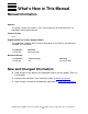
What’s New in This Manual Manual Information N1524A ACL Installation and User’s Guide for the NonStop S-Series Tape Enclosure Abstract This guide is written for installers, users, and maintainers of the N1524A ACL in a NonStop S-Series tape enclosure. Product Version N.A. Supported Release Version Updates (RVUs) This publication supports G06.21 and all subsequent G-series RVUs until otherwise indicated in a new edition.
What’s New in This Manual New and Changed Information N1524A ACL Installation and User’s Guide for the NonStop S-Series Tape Enclosure —527340-001 viii
About This Manual Notation Conventions Hypertext Links Blue underline is used to indicate a hypertext link within text. By clicking a passage of text with a blue underline, you are taken to the location described. For example: This requirement is described under Backup DAM Volumes and Physical Disk Drives on page 3-2. General Syntax Notation This list summarizes the notation conventions for syntax presentation in this manual. UPPERCASE LETTERS. Uppercase letters indicate keywords and reserved words.
About This Manual General Syntax Notation each side of the list, or horizontally, enclosed in a pair of brackets and separated by vertical lines. For example: FC [ num ] [ -num ] [ text ] K [ X | D ] address { } Braces. A group of items enclosed in braces is a list from which you are required to choose one item. The items in the list can be arranged either vertically, with aligned braces on each side of the list, or horizontally, enclosed in a pair of braces and separated by vertical lines.
Notation for Messages About This Manual Line Spacing. If the syntax of a command is too long to fit on a single line, each continuation line is indented three spaces and is separated from the preceding line by a blank line. This spacing distinguishes items in a continuation line from items in a vertical list of selections. For example: ALTER [ / OUT file-spec / ] LINE [ , attribute-spec ]… !i and !o.
About This Manual Notation for Management Programming Interfaces lowercase italic letters. Lowercase italic letters indicate variable items whose values are displayed or returned. For example: p-register process-name [ ] Brackets. Brackets enclose items that are sometimes, but not always, displayed.
Change Bar Notation About This Manual UPPERCASE LETTERS. Uppercase letters indicate names from definition files. Type these names exactly as shown. For example: ZCOM-TKN-SUBJ-SERV lowercase letters. Words in lowercase letters are words that are part of the notation, including Data Definition Language (DDL) keywords. For example: token-type !r. The !r notation following a token or field name indicates that the token or field is required. For example: ZCOM-TKN-OBJNAME !o. token-type ZSPI-TYP-STRING.
About This Manual Abbreviations N1524A ACL Installation and User’s Guide for the NonStop S-Series Tape Enclosure —527340-001 xiv
1 Overview and Features This section includes the following main topics and sections: Manual Overview 1-1 Product Overview 1-1 High Capacity Tape Cartridge 1-14 Manual Overview This manual should be used in conjunction with the latest versions of these HP NonStop manuals: Source Manual HP SCF Reference Manual for the Storage Subsystem HP SCF Reference Manual for G-series Releases Product Overview N1524A ACL Tape Drive The N1524A ACL tape drive is a high performance tape drive designed for the
N1524A ACL Tape Drive Overview and Features Figure 1-1. Example of the Tape Drive Configuration SCSI Connection SCSI Cable (23 meters max.
N1524A ACL Tape Drive Overview and Features Tape Drive SCSI Port One SCSI channel on the tape drive connects to a supported SCSI port on the NonStop S-series server. Table 1-1.
Overview and Features N1524A ACL Tape Drive Front Panel The front panel includes the power switch, the magazine door, and the control panel, which has indicators, buttons, and a display. Power Switch The power switch controls the supply of AC power to the tape drive. It is a pushon/push-off switch. When the power is on, the backplane of the control panel display is illuminated. Magazine Door The magazine door is the entry way for the 11-slot magazine, which holds 11 cartridges.
N1524A ACL Tape Drive Overview and Features • To display the Show Status menu only without entering the Menu mode, press Escape at the Default screen. The system remains online. Note. When the Menu mode is entered, the Ready light goes out. This means that the module is offline, and the system responds to all commands from the server with a SCSI Not Ready message until the Menu mode is exited, and the Ready light goes on.
Overview and Features N1524A ACL Tape Drive Note. There is an auto-repeat feature for the scroll buttons. When you press either scroll button for more than one-half second, the control panel behaves as if you were pressing and releasing the button four times per second. This effect stops when you release the button. Display Messages The control panel display can show messages of up to four lines of 20 characters each.
Overview and Features NonStop S-Series Tape Enclosure NonStop S-Series Tape Enclosure The NonStop S-series tape enclosures can be purchased as a base enclosure or a stackable enclosure. The enclosures come without a door so drives are easily accessed. A rear cover ECN is provided to cover the wiring and cables.
NonStop S-Series Tape Enclosure Overview and Features Tape Enclosure Configurations Valid configurations for the tape enclosures are: • • For single enclosures, up to two N1524A ACL tape drives can be stored. For two high enclosures, up to five N1524A ACL tape drives can be stored. Dimensions Table 1-3. Tape Enclosure Dimensions Dimension Description Height Enclosure 37.6 inches Caster 1.
Overview and Features NonStop S-Series Tape Enclosure Figure 1-3.
Overview and Features NonStop S-Series Tape Enclosure Rear Cover The rear cover of the tape enclosure comes already attached. Figure 1-4 shows a picture of the rear cover on the tape enclosure. Figure 1-4. Tape Enclosure with a Rear Cover Attached Extra Screws Screws Installed The rear cover is shipped with 5 screws. Two of the screws are already installed on the rear of the enclosure as shown in Figure 1-4. Two more screws will need to be installed after the cabling is complete.
NonStop S-Series Tape Enclosure Overview and Features Configuration Options Two tape enclosures can be stacked on each other (See Figure 1-5). If two tape enclosures are stacked, the bottom shelf in the bottom enclosure must be left empty. Figure 1-5. Two Stacked Tape Enclosures Leave This Slot Empty A tape enclosure can be stacked on top of a system enclosure (See Figure 1-5). All three shelves can be used in the tape enclosure.
Overview and Features NonStop S-Series Tape Enclosure Figure 1-6. Tape Enclosure on System Enclosure Do not stack a system enclosure on a tape enclosure. The server is heavier than the tape enclosure, stacking it on top of the tape enclosure makes the unit to be unstable (See Figure 1-7). Caution. Figure 1-7.
Overview and Features NonStop S-Series Tape Enclosure Base Tape Enclosure Only the top two shelves in the base tape enclosure are usable. The bottom shelf should remain empty. The base tape enclosure can store up to two tape drives. Stackable Tape Enclosure All three shelves in the stackable tape enclosure are usable. The stackable tape enclosure can hold up to three tape drives.
Overview and Features High Capacity Tape Cartridge High Capacity Tape Cartridge The tape drive accepts the C7972A cartridge. When this cartridge is used the amount of data stored on the tape can be up to 400 GB (2:1 compression). DLTIIItape, DLTIVtape or SDLT media cartridges are not compatible with this tape drive. The size and shape of the tape drive’s media is very similar to that of DLT cartridges in order to make it easy for automation. Figure 1-8.
2 Installing and Configuring the Tape Drive This section includes the following main topics and sections: Installing the Tape Drive 2-1 Configuring the Tape Drive 2-4 Setting Up Reserved Slots 2-9 Configuring Other Options 2-9 Installing the Tape Drive Because the tape drives are shipped already in the tape enclosure, minimal installation is involved unless you need to install spare drives in the enclosure.
Attaching the Power Cord Installing and Configuring the Tape Drive Figure 2-1. Location of Power Switch Power Switch Figure 2-2.
Installing and Configuring the Tape Drive Installing the SCSI Interface Cable Installing the SCSI Interface Cable 1. Before installing the 68-pin SCSI cable from the tape drive to the server, make sure that the tape drive is powered off. 2. Connect the 68-pin SCSI cable to the left SCSI channel port on the tape drive. 3. Attach the terminator to the right SCSI channel port on the tape drive. 4. Connect the other end of the 68-pin SCSI cable to a supported SCSI port on a NonStop S-series server.
Installing and Configuring the Tape Drive Configuring the Tape Drive Configuring the Tape Drive This section describes how to configure the tape drive. Note. The library (robotics) is factory set to SCSI ID 3; the tape drive is factory set to SCSI ID 5. There is no need to reconfigure the SCSI ID’s. Configuring the SCSI ID’s is for critical situations only. Setting the SCSI ID 1. Turn the tape drive on. Wait until the power-on self-test terminates and the default screen appears.
Installing and Configuring the Tape Drive Setting the SCSI ID Figure 2-4. Main Menu 3. Press the down button four times to move the cursor to Configure menu, then press Enter. The Configure menu in Figure 2-5 appears. The arrow at the end of the fourth line means you can scroll to additional configuration options.
Installing and Configuring the Tape Drive Setting the SCSI ID Figure 2-5. Configure Menu 4. To select a configuration option, press the up or down button on the control panel to move the cursor to the option you want to change. In this case, select Set SCSI. Press Enter to display the choices for that option. The Menu in Figure 2-6 appears.
Installing and Configuring the Tape Drive Setting the SCSI ID Figure 2-6. Set SCSI Menu Note. In Figure 2-6, note that the cursor is next to line 1, and that line 2 is indented, indicating a two-tiered menu. The scroll buttons work on two levels in this type of menu, which is typical of many menus under Configure. First-level navigation: When you press the down button, the cursor moves to line 3. Pressing the down button again, you will scroll down to Bus ID.
Installing and Configuring the Tape Drive Setting the SCSI ID Figure 2-7. Set SCSI Menu Scrolled 6. With the cursor next to line 3, press Enter. The cursor moves to line 4, the up arrow appears at the end of line 1, and the down arrow appears at the end of line 4. On line 4, scroll to display more options. Scroll so that line 5 appears. Then press Enter to save the new selection. An * appears at the left of line 5 to indicate that it is the current selection. 7.
Installing and Configuring the Tape Drive Setting Up Reserved Slots Setting Up Reserved Slots You can use one of the reserved slots for a cleaning cartridge to use the Autoclean function. Note. You can use this function ONLY while the tape drive is operating in RANDOM LIBRARY MODE in conjunction with NonStop server software, such as Auto Cartridge Loader Media Manager (ACLMM). The Reserved Slots function is under the Configuration options menu.
Installing and Configuring the Tape Drive Set Time Set Time Use this setting to set the tape drive's clock. Set Baud Rate Use this setting to set the data transmission rate of the tape drive's trace port. This function is intended for use by CEs only. The default is 38400 bits per second. Set Serial Number Use this setting to alter the tape drive’s serial number stored in the unit. The tape drive's robotics reports these settings in response to the SCSI Inquiry command in the Unit Serial Number page.
Set Default (Restricted) Installing and Configuring the Tape Drive Set Default (Restricted) This option resets all of the preceding configuration options to their factory defaults. Under no circumstances should this option be used. Table 2-2 summarizes the configuration and default settings for the tape drive. Other possible settings are shown in the second column. Table 2-2.
Set Default (Restricted) Installing and Configuring the Tape Drive Table 2-2. Tape Drive Configuration Options Option Settings Default Reserved Slots Reserved Slots: 0 through n 0 Special Config Mode Page 1F Length: Short (0x0E), Long (0x12) Model Number: Vendor Unique TUR Reporting: Standard: report Init. Elem. Status: No Inventory, Unit Attn.
3 Configuring the Tape Drive for the NonStop S-Series Server This section includes these topics: Supported Connections 3-1 Adding a Tape Drive 3-1 Supported Connections You can attach the tape drive to a NonStop S-series server using one of the following: • • • ServerNet/DA IOMF2 CRU PMF CRU Adding a Tape Drive ServerNet/DA To add the tape drive to the server configuration database, use the SCF ADD TAPE command to add the tape drive.
Configuring the Tape Drive for the NonStop S-Series Server PMF CRU PMF CRU To add the tape drive to the server configuration database, use the SCF ADD TAPE command to add the tape drive. Before issuing these commands, check that the tape drive is installed properly.
4 Operating the Tape Drive This section includes the following main topics and sections: Using the Front Panel 4-2 The Main Menu 4-10 Unlocking the Control Panel 4-23 Displaying Firmware Revision 4-24 Displaying Error Logs 4-24 Inserting and Removing Tape Cartridges 4-26 Removing the Tape Magazine 4-27 Emergency Tape Magazine Removal 4-27 Inserting a Tape Magazine Into the Tape Drive 4-27 Inserting Tape Cartridges Into the Tape Magazine 4-28 Tape Requirements 4-28 Tape Cartridge Han
Operating the Tape Drive Using the Front Panel Using the Front Panel The front panel includes the power switch, the magazine door, and the control panel, which has indicators, buttons, and a display. Power Switch The power switch controls the supply of AC power to the tape drive. It is a pushon/push-off switch. When the power is on, the backplane of the control panel display is illuminated.
Operating the Tape Drive Indicators Indicators The four LED indicators on the control panels are: • • • The Ready LED (green) is illuminated when the tape drive is ready to accept commands from either the Control Panel or the NonStop server. When you enter the Menu Mode, the Ready indicator goes out. The Use Cleaner LED (yellow) indicates that the drive requires cleaning. When either the Drive Fault or the Loader Fault LED (red) is illuminated, a Fault screen appears on the LCD display.
Buttons Operating the Tape Drive Table 4-1. Control Panel Functions Screen Escape Enter Up Arrow Down Arrow POST N.A. N.A. N.A. N.A. Default Displays Show Status menu Enters Menu mode N.A. N.A.
Operating the Tape Drive Buttons Display Messages The control panel display can show messages of up to four lines of 20 characters each. Power-On-Self-Test Screen When power is first applied to the tape drive, a series of power-on self-test (POST) diagnostics is performed. During POST execution, the model number of the tape drive, the current date and time, the firmware revision, and the status or result of the test in progress appear on the control panel.
Operating the Tape Drive Buttons Initialization Screens After the POST completes, the library robotics server begins initialization and displays a series of screens. For an example see Figure 4-3. Figure 4-3.
Operating the Tape Drive Buttons Default Screen After the POST diagnostics conclude successfully, and initialization is complete, the default screen appears (See Figure 4-4). Figure 4-4. Default Screen The first line of the Default screen shows the status of the LTO tape drive within the unit.
Operating the Tape Drive • • • Buttons Loading Unloading Calibrating The screen's second line displays possible status conditions of the library robotics: • • • • • • • • • • • Loader Idle Fetch Stow Diag Active Diag Complete Taking Inventory Elevator Home Checking Drive(s) Orphaned Cartridge Trapped Cartridge Scanning Labels. The third line in Figure 4-4 represents a map of the tape magazine. A 11-slot tape magazine is shown. The number 1 shows the location of slot 1 (the front slot) in the map.
Operating the Tape Drive Buttons Fault Screen When a fault is detected, a screen similar to Figure 4-5 appears. At the same time, either the Drive Fault or the Loader Fault LED is illuminated. Figure 4-5. Fault Screen The first line in the Fault screen shows a numerical fault symptom code (FSC). The second line shows a brief description of the error. The third and fourth lines contain a one-line or two-line message describing the initial error recovery procedure (ERP).
Operating the Tape Drive The Main Menu The Main Menu Figure 4-6.
Operating the Tape Drive Entering the Menu Mode Entering the Menu Mode Note. When you press Enter to enter the Menu mode, the Ready light goes out, indicating that the tape drive is offline. The tape drive responds to all SCSI commands from the server by reporting “Not Ready” until you exit the Menu mode and the Ready light goes on. To prevent inadvertent interruption of server operations, the Menu mode can be locked by using the Security menu.
Operating the Tape Drive Exiting the Main Menu Using the up arrow and down arrow scroll buttons, set the first digit of the unlock code. When it is set, press Enter to move the cursor to the second digit and repeat the process. After you enter the entire unlock code using this process, press Escape. Then press Enter to confirm the entry. If the code is correct, the Main menu appears. If the code is incorrect, an error screen appears.
Operating the Tape Drive Load/Unload Show Status Note. The Show Status menu can be selected directly from the Default screen without entering the Menu mode by pressing Escape. In this way, you can check status at any time without interrupting NonStop server operations. When you select Show Status, either from the Main menu or from the Default screen, the menus shown in Figure 4-8 appears. Figure 4-8.
Operating the Tape Drive Load/Unload Library Status Menu When Library is selected, the menu in Figure 4-9 appears. Figure 4-9.
Operating the Tape Drive Load/Unload This screen is scrollable and lists the Library status categories: • • • • • • • • • • • • • • • • • • • • • • • • • • • • • Model Number Firmware Revision Date Time Loader Status Autoclean Mode Library Mode Library Configuration Vendor Identification Product Identification Transport Address Storage Address Transfer Address Serial Number Wide SCSI SCSI Bus ID CSI Bus Parity Negotiation Mode Transfer Rate Unload Mode Reserved Slots Mode Page 1F Length TUR Reporting In
Operating the Tape Drive • • Drive Status (LTO1) Menu Label Alignment Abort Move Status Drive Status (LTO1) Menu When you select the drive, the menu in Figure 4-10 appears. Figure 4-10. Drive Status Menu This screen is scrollable and lists the Drive Status categories.
Operating the Tape Drive • • • • • • Drive Status (LTO1) Menu Cartridge Present Hardware Error Cleaning Needed Write Protected Operate Handle Drive Serial No.
Operating the Tape Drive Map Information Screen Map Information Screen When you select Map Info, a screen similar to Figure 4-11 appears. The location of the element being reported appears on line 1. Figure 4-11. Map Information Menu Lines 1, 2, 3, and 4 on this screen are scrollable in unison.
Operating the Tape Drive Map Information Screen Maintenance The Maintenance menu and the options intended for operator use are described in Maintaining the Tape Drive. Additional options on the Maintenance menu that are intended for use by service personnel are described in the Service Manual. Configure For information about the Configure menu, see Section 2 “Installing and Configuring the Tape Drive”. Show History The Show History menu enables the operator to review the history of the tape drive.
Operating the Tape Drive Map Information Screen Security The Security menu permits the operator to lock the control panel, preventing inadvertent or unauthorized access to the Menu mode, which takes the tape drive offline. Note. • • When the control panel is locked, you cannot open the magazine door. To display the Status menu without unlocking the control panel by pressing Escape at the default screen. Figure 4-12.
Operating the Tape Drive Map Information Screen When you press Enter the screen shown in Figure 4-13 appears. Figure 4-13. Code Select Menu An underlined cursor appears under the first digit. To set the first digit, press the " or # scroll button until the desired code number appears. To move the cursor to the second digit, press Enter. Repeat the process for each of the four digits. Remember to copy the 4-digit number. You will need it to enter the Menu mode.
Operating the Tape Drive Map Information Screen When you press Escape the screen shown in Figure 4-14 appears. 9900 indicates the specific unit code (this is just an example). Figure 4-14. Code Accept Menu Press Enter when the unlock code that appears is acceptable. Press Escape if it is not acceptable. Press Escape again to return to the Main menu, and again to return to the Default screen.
Operating the Tape Drive Unlocking the Control Panel Unlocking the Control Panel After the control panel is locked through the Security menu, you are asked to enter the security code to enter the Menu mode. The security code entry screen shown in Figure 4-15 appears. Figure 4-15. Panel Locked Screen Note. The control panel lock also prevents operator access to the Unlock Door command on the Main menu.
Operating the Tape Drive Displaying Firmware Revision When you press Enter, the screen in Figure 4-16 appears. Figure 4-16. Code Entry Menu Scroll to set the first digit of the unlock code. Press Enter to move the cursor to the second digit and repeat the process. After you enter the unlock code, press Escape. Press Enter to validate the unlock code or Escape to exit. If the code is correct, the Main menu appears. If the code is incorrect, an error screen appears.
Operating the Tape Drive Displaying Error Logs 2. At the Main menu, scroll down until the ! is next to Show History Menu. 3. Press Enter to select the menu. 4. At the Show History menu, scroll down so that the ! is next to Error History. 5. Press Enter to select the function. A list of 4-line error reports appears in the format shown in Figure 4-17. 6. Scroll through the list to display the error history of the tape drive. Figure 4-17.
Inserting and Removing Tape Cartridges Operating the Tape Drive Inserting and Removing Tape Cartridges Remove the tape magazine from the tape drive to insert or remove tape cartridges. When inserting tape cartridges, check that the slot intended for use is not already reserved in the server map for a tape cartridge in a tape drive. To avoid conflicts, unload the tape drive, either through the server software or by using the Load/Unload command on the Main menu, described earlier in this section.
Operating the Tape Drive Removing the Tape Magazine Removing the Tape Magazine When the tape magazine door is closed, it is locked in place to prevent tampering or accidental removal. To remove the magazine, enter the Menu mode by pressing Enter at the Default screen. At the Main menu, select Unlock Door and press Enter. The magazine door swings open. Emergency Tape Magazine Removal If a fault occurs that prevents removal of the magazine, turn the power off for 30 seconds.
Operating the Tape Drive Inserting Tape Cartridges Into the Tape Magazine Inserting Tape Cartridges Into the Tape Magazine Figure 4-19 shows a full tape magazine. Insert tape cartridges so that the label end with the write protect switch is outward and toward the bottom of the tape magazine. After the desired tape cartridges are inserted into the tape magazine, position the tape drive so the tape cartridges protrude to the left, and the tape magazine handle is toward you.
Operating the Tape Drive General Precautions Fortunately, the simple precautions explained here will allow the user to avoid damaging cartridges and to recognize those that are. This document will be helpful in getting the best use of the storage media and keep it as reliable as our equipment. General Precautions 1. Always carefully inspect incoming shipments of cartridges: a. Check the box for signs of damage or moisture. Refuse any shipments in a damaged container. b.
Operating the Tape Drive Loading and Unloading Tape Cartridges Loading and Unloading Tape Cartridges The Load/Unload menu enables you to specify a source and a destination for a tape cartridge. As a result, the procedure is the same to load for unload. To load or unload a tape from the front panel of the tape drive, use the Load/Unload menus. Figure 4-20. Default Screen Figure 4-20 shows a default screen. LTO1 has a tape loaded.
Operating the Tape Drive Loading and Unloading Tape Cartridges Figure 4-21.
Operating the Tape Drive Loading and Unloading Tape Cartridges Press Enter to display the first Load/Unload menu, shown in Figure 4-22. Figure 4-22. Load/Unload Initial Screen In Figure 4-22, the ! is next to line 2 of the display. Line 2 shows the top item in a scrollable list of sources. You can now use the #button to scroll through the list and the top item on the list appears. You press the #button, three things happen: • • The list scrolls down one item (only line 2 scrolls).
Operating the Tape Drive • Loading and Unloading Tape Cartridges The * at the left of line 2 disappears. The default selection has been scrolled off screen, and an item from the list has not yet been selected. The * indicates the current selection or the default selection. Initial Screen - From Line The list on line 2 includes the tape drive and every tape magazine slot that has a cartridge in it. You cannot select a tape cartridge from a slot or tape drive that is empty.
Operating the Tape Drive Loading and Unloading Tape Cartridges Press Enter to select LTO1. In Figure 4-24, two changes occur in the display: • The * reappears at the beginning of line 2, indicating that a selection has been made. • The ! now moves to line 4, indicating that a destination has been selected. Figure 4-24. Load/Unload To Entry Screen Press Enter to select Slot 1 as the destination. There is an ! at the end of line 4.
Operating the Tape Drive Loading and Unloading Tape Cartridges are empty, so a list of remaining empty slots appears below Slot 2. To select Slot 1, press Enter. In response, the confirmation screen in Figure 4-25 appears. Figure 4-25. Confirmation Screen As the confirmation screen indicates, to execute the load or unload, press Enter. If the confirmation screen does not show the intended source and destination, press Escape to return to the To entry screen.
Operating the Tape Drive Loading and Unloading Tape Cartridges When you press Enter, the screen shown in Figure 4-26 appears. Figure 4-26.
Operating the Tape Drive Loading and Unloading Tape Cartridges When the load or unload operation is finished, the Default Screen reappears. In Figure 4-27, the screen has been updated to show that there is now no tape cartridge in LTO1, and slot 1 is full. Figure 4-27.
Operating the Tape Drive Loading and Unloading Tape Cartridges N1524A ACL Installation and User’s Guide for the NonStop S-Series Tape Enclosure —527340-001 4- 38
5 Maintaining the Tape Drive This section includes these topics: Cleaning the Tape Drive 5-1 Installing the Cleaning Cartridge 5-1 Running From the Front Panel 5-2 Removing the Cleaning Cartridge 5-5 The only required maintenance task is to periodically run or replace the cleaning cartridge. You can run user diagnostics from the Demo menu to check the operation of the tape drive. Occasionally, HP issues new firmware upgrades that must be performed by qualified service personnel.
Maintaining the Tape Drive Running From the Front Panel 5. Insert the magazine in the tape drive. 6. Close the magazine door. Note. The cleaning cartridge is abrasive. Use it only when the Use Cleaner LED comes on. If you enable the Autoclean mode on the Configuration menu, the ACL runs the cleaning cartridge automatically whenever the Use Cleaner LED comes on.
Maintaining the Tape Drive Running From the Front Panel 2. Scroll down to move the cursor next to Maintenance menu. Then press Enter to select the Maintenance menu. The Maintenance menu appears in Figure 5-2. Figure 5-2.
Maintaining the Tape Drive Running From the Front Panel 3. Press Enter once to select Clean Drive. The screen in Figure 5-3 appears. Figure 5-3. Maintenance Menu 4. Line 2 is not scrollable. Press Enter once to accept LTO1. The cursor moves to line 4 of the display. Press Enter again to use the cleaning cartridge in Slot 1. 5. The Cleaning Confirmation Screen will appear. 6. To execute the cleaning operation, press Enter.
Maintaining the Tape Drive Removing the Cleaning Cartridge Removing the Cleaning Cartridge 1. Check the Default Screen on the Control Panel to make sure that the cleaning cartridge has been unloaded from the drive. If not, unload it by using the Load/Unload menu. 2. Remove the magazine. 3. Remove the cleaning cartridge from the magazine. 4. Insert any desired tape cartridge into the empty slot. 5. Insert the magazine in the tape drive. 6. Close the magazine door.
Maintaining the Tape Drive Removing the Cleaning Cartridge N1524A ACL Installation and User’s Guide for the NonStop S-Series Tape Enclosure —527340-001 5 -6
6 Servicing the Tape Drive This section addresses the following topics: Removing a Tape Drive from the Tape Enclosure 6-1 Adding a Tape Drive to the Tape Enclosure 6-1 Note. This section explains in detail how the user will be able to easily remove a tape drive or add it to/from the tape enclosure. Removing a Tape Drive from the Tape Enclosure 1. Power off the unit. 2. Remove the rear cover. 3. Remove the power cord and the SCSI cable from the unit. 4.
Adding a Tape Drive to the Tape Enclosure Servicing the Tape Drive Figure 6-1.
A Troubleshooting Fault Screen When a fault is detected, a screen similar to Figure A-1 appears. At the same time, either the Drive Fault or the Loader Fault LED is illuminated. Figure A-1. Fault Screen The first line in the Fault Screen shows a numerical Fault Symptom Code (FSC). The second line shows a brief description of the error in place of the words 'Error Description.' The third and fourth lines will contain a one- or two-line message describing the initial Error Recovery Procedure (ERP).
Troubleshooting Recovering from Errors 3. Press Enter to select the menu. 4. At the Show History menu, press the down button once so that the cursor in the display is next to Error History. 5. Press the Enter button to select the function. A circular list of 4-line error reports appears in the format shown in Figure A-2. 6. Using the up and down buttons, scroll the list to display the error history of the tape drive. Figure A-2.
Recovering from Errors Troubleshooting Error Recovery Procedures and Fault Symptom Codes includes additional procedures that can perform by an experienced service technician. Table A-1. Error Recovery Procedures ERP Number Procedure Detail C Cycle power to the drive using the AC switch on the front panel of the tape drive. Wait 30 seconds to power on again. D Turn off power to the tape drive and inspect connectors and cables. F Invalid operation. Select parameters correctly and try again.
Recovering from Errors Troubleshooting Table A-2. Fault Symptom Codes FSC Displayed Message ERP 5012 All Drives Full Press Enter to Clear F 5014 LTO Already Loaded Press Enter to Clear F 5015 Expired Clean’g Cart Press Enter to Clear F 5016 Not a Clean’g Cart Press Enter to Clear F 5020 All LTOs / Slots Empty Press Enter to Clear F 5039 Invalid Unlock Code Press Enter to Clear F* * If the unlock code is unavailable, contact the system administrator.
Troubleshooting Troubleshooting for Field Support Troubleshooting for Field Support Control Panel The control panel consists of four LED indicators, a 4-line by 20-character backlit LCD display, and four buttons. Figure A-3 shows the control panel. Figure A-3. Control Panel Power-On Self Test Screen When you first turn on the tape drive, a series of Power-On Self-Test (POST) diagnostics is performed.
Troubleshooting Power-On Self Test Screen the test in progress appears on the control panel. Figure A-4 shows the first message that appears on the display. Figure A-4.
Troubleshooting Initialization Screens Initialization Screens After the POST is completed, the library robotics system begins its initialization. A series of screens similar to Figure A-5 appears during this process. Figure A-5.
Troubleshooting Default Screen Default Screen After the POST diagnostics have concluded successfully and initialization is complete, the default screen appears, as shown in Figure A-6. Figure A-6. Default Screen The first line of the Default Screen shows the status of the LTO drive.
Troubleshooting • • • Default Screen Loading Unloading Calibrating The second line displays possible status conditions of the library robotics: • • • • • • • • • • • Loader Idle Fetch Stow Diag Active Diag Complete Taking Inventory Elevator Home Checking Drive(s) Orphaned Cartridge Trapped Cartridge Scanning Labels. The third line represents a map of the magazine. A 11-slot magazine is shown. The number 1 shows the location of slot 1 (the front slot) in the map.
Troubleshooting Entering the Menu Mode Entering the Menu Mode When the Default screen appears, enter the Menu mode by pressing the Enter button. The Main Menu appears. See Figure A-7. Figure A-7. Main Menu Exiting the Menu Mode To leave the Menu mode and return to the Default Screen, press the Escape button repeatedly. Each time you press the Escape button, the display moves to a higher menu level. When the Main Menu is visible, pressing the Escape button once returns to the Default screen.
Troubleshooting The Menu Structure The Menu Structure Figure A-8 shows the structure of the menus. Figure A-8.
Troubleshooting Manual Unload Procedure Manual Unload Procedure Note. The tape drive will need to be completely removed from the chassis to perform this procedure. 1. Drive mechanism must be free of assembly. DO NOT REMOVE DRIVE COVERS. 2. Orient drive on side with front of drive facing towards left as shown in Figure A-9 below. 3. Turn RD Thumbwheel (shown in Figure A-9 below) by hand towards back of Drive as far as possible (there is no hard stop, but the wheel will begin to spring back).
Troubleshooting Manual Unload Procedure Figure A-9.
Troubleshooting Manual Unload Procedure N1524A ACL Installation and User’s Guide for the NonStop S-Series Tape Enclosure —527340-001 A -14
B SCSI Request Sense REQUEST SENSE 03h Figure B-1. REQUEST SENSE REQUEST SENSE tells the target to transfer sense data to the initiator. The sense data is valid for a CHECK CONDITION status returned on the previous command. The sense data bytes are preserved by the target until retrieved by the REQUEST SENSE command, or until the receipt of any other command from the same initiator.
SCSI Request Sense Allocation Length Sense Information Format Figure B-2. Sense Information Format Valid A valid bit of one indicates that the information bytes contain valid information as defined in the SCSI-2 specification. Error-Code A value of 70h indicates a current error- the report is associated with the most recently received command. A value of 71h indicates a deferred error- the report is associated with a previous command and not as a result of the current command.
Allocation Length SCSI Request Sense Sense Key This field provides the top level reason for the error or exception condition. SENSE KEY DESCRIPTION 0h NO SENSE. Indicates no specific sense key information is available. 1h RECOVERED ERROR. Indicates that the last command completed successfully with some recovery action performed by the target. This code is not used for the LTO Library. 2h NOT READY. Indicates that the logical unit addressed cannot be accessed.
Allocation Length SCSI Request Sense Information Bytes This field is always set to zero. Additional Sense Length This specifies the number of additional sense bytes to follow. If the allocation length of the command descriptor block is too small to transfer all of the additional sense bytes, the additional sense length is not adjusted to reflect the truncation.
Allocation Length SCSI Request Sense ASC ASCQ Description 28h 00h NOT READY TO READY TRANSITION, MEDIUM MAY HAVE CHANGED 28h 01h IMPORT OR EXPORT ELEMENT ACCESSED 28h 8Ch NOT READY TO READY TRANSITION, MAGAZINE DOOR CLOSED 28h 8Dh NOT READY TO READY TRANSITION, EXITED MENU MODE 28h 8Eh NOT READY TO READY TRANSITION, EXITED SEQUENTIAL MODE 28h 8Fh NOT READY TO READY TRANSITION, MAGAZINE DOOR OPENED 29h 00h POWER ON, RESET, OR BUS DEVICE RESET OCCURRED 29h 01h POWER ON OCCURRED 29
Allocation Length SCSI Request Sense ASC ASCQ Description 47h 00h SCSI PARITY ERROR 48h 00h INITIATOR DETECTED ERROR 4Eh 00h OVERLAPPED COMMANDS ATTEMPTED 53h 00h MEDIA LOAD OR EJECT FAILED 53h 02h MEDIUM REMOVAL PREVENTED 80h 03h MEDIUM SOURCE ELEMENT NOT INSTALLED 80h 04h MEDIUM DESTINATION ELEMENT NOT INSTALLED 83h 01h ERROR READING BARCODE LABEL 83h 02h CARTRIDGE MAGAZINE IS NOT INSTALLED 83h 04h TAPE DRIVE IS NOT INSTALLED 83h 09h NO BARCODE LABEL DETECTED 83h 10h
SCSI Request Sense Allocation Length N1524A ACL Installation and User’s Guide for the NonStop S-Series Tape Enclosure —527340-001 B- 7
SCSI Request Sense Allocation Length N1524A ACL Installation and User’s Guide for the NonStop S-Series Tape Enclosure —527340-001 B- 8
C Error Recovery Procedures and Fault Symptom Codes This section covers the following topics and subtopics: Error Recovery Procedures C-2 Fault Symptom Codes C-2 System Fault Codes (0xxx) C-3 SCSI Error Codes (1xxx) C-4 Control Error Codes C-5 Motor Process Error Codes (3xxx) C-7 Power-On Error Codes C-10 Menu Error Codes C-10 Inter-module Error Codes C-12 Boot Error Codes C-15 Flash Error Codes C-16 N1524A ACL Installation and User’s Guide for the NonStop S-Series Tape Enclosure —527
Error Recovery Procedures and Fault Symptom Codes Error Recovery Procedures Error Recovery Procedures The following table list the Error Recovery Procedures (ERP) for the N1524A / N1525A ACL tape drive: ERP Description A Press ENTER to Reboot B Power Down to Clear C Press ENTER to Init. Novram to Def.
Error Recovery Procedures and Fault Symptom Codes System Fault Codes (0xxx) System Fault Codes (0xxx) FSC Message Description ERP 0101 Unused Interrupt An undefined interrupt occurred A, B, 1 0102 Enqueue'g a Null Ptr A NULL pointer was passed to one of the enqueing functions. This is generally a firmware bug. A, B, 1 0103 Invalid Cmd Rec'd An illegal trace command was received by the trace process. A, B, 1 0201 Trc. Comm Open Error The trace port could not be opened.
Error Recovery Procedures and Fault Symptom Codes SCSI Error Codes (1xxx) SCSI Error Codes (1xxx) FSC Message Description ERP 1001 SCSI Firmware Error 1002 SCSI FIFO Empty While getting SCSI command bytes, the SCSI chip reported an empty FIFO before it was expected. D, 17, 1 1003 SCSI FIFO Error While getting SCSI command bytes, the SCSI chip reported that the FIFO was not empty when it should be empty. D, 17, 1 1004 SCSI Gross Error Gross error status was returned by the SCSI chip.
Error Recovery Procedures and Fault Symptom Codes Control Error Codes Control Error Codes FSC Message Description ERP 2001 Ctl. Invalid Command An invalid command was received by the control process. D, 1 2002 Undefined Config An unsupported configuration was detected. A, B, 6, 1 2003 Invalid Drive State One of the LTO drives was in an invalid state This is caused by either attempting to fetch a cartridge from an empty drive, or stowing to a drive that already has a cartridge loaded.
Error Recovery Procedures and Fault Symptom Codes Control Error Codes FSC Message Description ERP 2013 Ctl. Firmware Error A, B, 1 2014 Ctl. Firmware Error A, B, 1 2015 Ctl. Firmware Error A, B, 1 2016 Ctl. Firmware Error A, B, 1 2030 LTO Timeout Error During powerup, communication with one of the LTO drives was unsuccessful. A, B, 3, 1 2031 LTO Timeout Error While trying to update the front panel, communication with one of the LTO drives was unsuccessful.
Error Recovery Procedures and Fault Symptom Codes Motor Process Error Codes (3xxx) FSC Message Description ERP 2073 Drive Config Error Set if the Alternate Unload has not been selected. A, 3 2074 Stow Error A stow timeout error has occurred when accessing a remote unit. Press Enter to Reboot for orphan cartridge recovery. D, # 2075 Fetch Error During a remote fetch operation, the remote unit returned an error.
Error Recovery Procedures and Fault Symptom Codes Motor Process Error Codes (3xxx) FSC Message Description ERP 3011 Picker Retries Exceeded While attempting to fetch a cartridge, the picker was not able position properly within 16 attempts. A, B, 2, 7, # 3012 Picker Retries Exceeded While attempting to fetch a cartridge, the picker was not able position properly within 16 attempts.
Error Recovery Procedures and Fault Symptom Codes Motor Process Error Codes (3xxx) FSC Message Description ERP 310B Picker Jammed During a stow operation, the picker was not able to insert the cartridge into the drive. A, B, 2, 3, # 3200 Elevator Jammed The elevator was not able to position properly while attempting to recover an orphaned cartridge. A, B, 2, 7, # 3201 Elevator Jammed The elevator was not able to position properly during an inventory.
Error Recovery Procedures and Fault Symptom Codes Power-On Error Codes Power-On Error Codes FSC Message Description ERP 4001 Rom CRC Error A, B, 1 4002 Ram Test Failed A, B, 1 4003 Xilinx Progr. Error A, B, 1 4010 Comm.
Error Recovery Procedures and Fault Symptom Codes Menu Error Codes FSC Message Description ERP 5014 LTO Already Loaded User has chosen the Clean Drive menu selection, but a LTO previously determined to be unloaded and now selected to be cleaned, has indicated the presence of a tape cartridge. D, 1, 5 5015 Expired Clean'g Cart User has chosen the Clean Drive menu selection, but has specified a slot which contains an expired cleaning cartridge.
Error Recovery Procedures and Fault Symptom Codes Inter-module Error Codes FSC Message Description ERP 5039 Invalid Unlock Code Display message only when an invalid unlock code is entered. D, 5 503A Auto Cleaning Display message only -not an error 4 5090 Slave Command Failure Error occurred sending a menu mode command to a slave module.
Error Recovery Procedures and Fault Symptom Codes Inter-module Error Codes FSC Message Description ERP 6015 Ack Timeout - Out The Master inter-module process attempted to initiate a packet transmission to a Slave intermodule process, but a timeout occurred waiting for the Slave's acknowledge. A, B, 1 6016 Ack Timeout - In The Master inter-module process attempted to initiate a packet transmission from a Slave intermodule process, but a timeout occurred waiting for the Slave's acknowledge.
Error Recovery Procedures and Fault Symptom Codes Inter-module Error Codes FSC Message Description ERP 6031 Slave Boot Incompat.
Error Recovery Procedures and Fault Symptom Codes Boot Error Codes FSC Message Description ERP 6060 Slave 3 Ch Init Err An error occurred during the 3 Ch slave module initialization A, B, 1 6061 Slave 3 Ch Sync Err An error occurred attempting to sync with the 3 ch slave module A, B, 1 6062 Slave 3-Ch Flash Err An error occurred attempting to flash the 3 Ch slave module A, B, 1 Description ERP Boot Error Codes FSC Message B001 Boot ROM CRC Error B, 1 B002 Boot RAM Test Failed B, 1
Error Recovery Procedures and Fault Symptom Codes Flash Error Codes Flash Error Codes FSC Message Description ERP F001 No Flash Installed D, 1 F002 Invalid Comm Port D, 1 F003 Could Not Open Comm D, 1 F004 Host Sync Failed D, 5, 1 F005 Invalid H/W Config D, 1 F006 Incompatible Image D, 5 F010 Flash Erase Error A, B, 1 F011 Flash Download Error A, B, 1 F012 Flash Program Error A, B, 1 F013 Flash CRC Error A, B, 1 N1524A ACL Installation and User’s Guide for the NonStop S-S
Safety and Compliance Regulatory Compliance Statements The following regulatory compliance statements apply to the products documented by this manual. Consumer Safety Statements FCC Compliance This equipment has been tested and found to comply with the limits for a Class A digital device, pursuant to part 15 of the FCC Rules. These limits are designed to provide reasonable protection against harmful interference when the equipment is operated in a commercial environment.
Safety and Compliance Taiwan (BSMI) Compliance Taiwan (BSMI) Compliance JAPAN (VCCI) Compliance N1524A ACL Installation and User’s Guide for the NonStop S-Series Tape Enclosure —527340-001 Statements -2
JAPAN (VCCI) Compliance Safety and Compliance Supplier Name: Hewlett-Packard Company Supplier Address Hewlett-Packard Company Represented in the EU By: NonStop Enterprise Division Hewlett-Packard Company 10300 North Tantau Avenue P.O.
Safety and Compliance JAPAN (VCCI) Compliance Chuck Denning Manager, Hardware Product Assurance NonStop Enterprise Division Cupertino, California N1524A ACL Installation and User’s Guide for the NonStop S-Series Tape Enclosure —527340-001 Statements -4
Index A AC power outlet 2-3 C Configuration PMF CRU 3-2 ServerNet/DA 3-1 set autoclean mode 2-10 set baud rate 2-10 set data format 2-9 set date 2-9 set identification 2-9 product ID 2-9 vendor ID 2-9 set library mode 2-9 set negotiation 2-10 set SCSI 2-9 set serial number 2-10 set time 2-10 set unload mode 2-10 F Features control panel 1-4 buttons 1-4 display 1-5 display messages 1-6 indicators 1-4 front panel 1-4 magazine door 1-4 power switch 1-4 M Magazine 4-27 Menus Configure 4-12 Confirmation scre
O Index model number 4-15 negotiation mode 4-15 product identification 4-15 reserved slots 4-15 SCSI bus ID 4-15 serial number 4-15 storage address 4-15 time 4-15 transfer address 4-15 transfer rate 4-15 transport address 4-15 TUR reporting 4-15 unload mode 4-15 vendor identification 4-15 wide SCSI 4-15 Load/Unload 4-12 Load/Unload from entry screen 4-33 Load/Unload in progress screen 4-36 Load/Unload initial screen 4-32 Load/Unload to entry screen 4-34 Main 2-5, 4-31, 5-2, A-10 Maintenance 4-12, 5-3 map