
NET/MASTER Management Services (MS) System Management Guide


Using the Console Extras Configuration Features
Configuring the Console Extras Facility
105744 Tandem Computers Incorporated 7–3
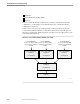
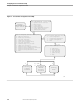
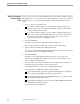
As Figure 7-1 suggests, the NCL procedure’s search path and processing follow this
course:
1. If the NCL procedure finds any definition specified for the user ID, only the
selections so designated appear on the user’s Console Extras : Utility List panel.
2. If the NCL procedure cannot find any definitions specified for the user ID, the
procedure determines whether a site-wide, customized configuration exists. If
such a configuration exists, then it appears on the user’s Console Extras : Utility
List panel.
3. If the NCL procedure cannot find any definitions for the user ID or site-wide
customized configuration, then the NCL procedure displays the default
configuration on the user’s Console Extras : Utility List panel.
Using the Console
Extras Configuration
Features
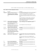
A user can invoke an external utility from the Console Extras panel if an associated
Console Extras definition exists. NonStop NET/MASTER MS uses information in the
Console Extras definition to start a session with the utility. A complete list of the
information in a definition appears in Table 7-1, later in this section.
There are two Console Extras definition databases:
The distributed Console Extras definition database contains definitions supplied
by Tandem for your convenience. The definitions in this database are available to
all NonStop NET/MASTER MS systems on the same node. The file is named
CEXDCF and resides in the $isv-vol.ZNNMDATA subvolume.
The customized Console Extras definition database contains definitions that you
add, whether the definition applies to a specific user or is available system-wide.
The file is named pCEXCCF, where p is the first alphabetic character of the
NonStop NET/MASTER MS control process name (NCP), and resides in the $isv-
vol.ZNNMDATA subvolume.
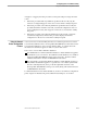
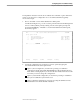
To add and maintain Console Extras definitions, use the Console Extras configuration
panels. Figure 7-2 illustrates the panels and their relationships to one another.