
NET/MASTER Management Services (MS) System Management Guide

Configuring INMC Links
Supporting Remote Operations
9–8 105744 Tandem Computers Incorporated
Representation of Network
Objects to NonStop
NET/MASTER MS
The preceding subsections have discussed, generally, the procedures for defining
INMC links. The next three figures depict configuration of an INMC link in a simple
network of two Tandem computers and an IBM 370 host computer. (Portions of the
SCF configuration command file and the NonStop NET/MASTER MS link, session,
and unit definition commands that configure this example network appear in a more
detailed discussion under “Example 1: IBM Host Controlling Two Tandem Nodes,”
later in this section.)
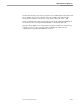
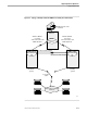
Figure 9-2 introduces the network and illustrates its topology.
The Tandem computer designated \NODEA processes automatic teller machine
(ATM) transactions and forwards transaction data to the IBM host. The IBM host
also serves as the network management center node, which monitors and controls
the Tandem computers and the communications lines.
The Tandem computer designated \NODEB is a remotely located standby node
that can process the ATM transactions in the event the production node suffers a
disaster, such as an earthquake. The X.25 lines between the Tandem computers
enable the standby node to know whether it should activate the A/B switch and
assume responsibility for processing ATM transactions.
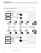
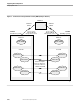
Figure 9-3 illustrates the presence of communications subsystem objects that facilitate
application-to-application communication between NonStop NET/MASTER MS
systems on \NODEA and \NODEB. The entities are configured during phase 1 of
INMC configuration tasks.
Figure 9-4 illustrates the representation of the communications subsystems to NonStop
NET/MASTER MS. Note the correspondence of session definitions to access methods
and unit definitions to subdevices. The link, session, and unit definitions are added
during phase 2 of INMC configuration tasks.