
NonStop S-Series Hardware Installation and FastPath Guide (G06.25+)

Configuring the System
HP NonStop S-Series Hardware Installation and FastPath Guide—529443-001
10-6
Create the Operating Configuration
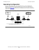
6. Connect the backup system console to Switch 2:
a. Connect an Ethernet cable to the 10Base-T connector on the network interface
card (NIC) at the back of the system unit for the backup system console. For
the location of the NIC connector, see the quick setup reference card.
b. Connect the other end of this Ethernet cable to any port on Switch 2 except the
cascade port.
7. Set the medium-dependent interface (MDI) switch on Switch 1 to allow the
cascade port of Switch 1 to connect to another switch or hub. See the
documentation provided with Switch 1. The position of the MDI switch on Switch 2
does not matter.
8. Connect the three-foot Ethernet cable provided with the switch or hub from the
cascade port of Switch 1 to any port on Switch 2 except the cascade port.
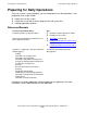
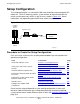
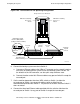
Figure 10-3. Connections for the Operating Configuration
VST535.vsd
Note: Connections vary
depending on the
Ethernet switch you use
Ethernet Switch 1
Ethernet Switch 2
To Primary
System
Console
To Backup
System
Console
Cascade
Port
Cascade
Port
Medium-Dependent
Interface (MDI) Switch
(Setting for Ethernet Switch)
MDI
To
Ethernet
Switch
To PC
MDI-X
Group 01 Processor Enclosure
PMF CRU Containing
Processor 0
Slot 50
PMF CRU Containing
Processor 1
Slot 55